4(%3)3 - Ecole nationale supérieure de chimie de Montpellier
4(%3)3 - Ecole nationale supérieure de chimie de Montpellier
4(%3)3 - Ecole nationale supérieure de chimie de Montpellier

You also want an ePaper? Increase the reach of your titles
YUMPU automatically turns print PDFs into web optimized ePapers that Google loves.
THESISPRESENTED ATNATIONAL GRADUATE SCHOOL OF CHEMISTRY OF MONTPELLIER(ECOLE NATIONALE SUPERIEURE DE CHIMIE DE MONPELLIER)DOCTORAL SCHOOL OF CHEMICAL SCIENCES(ECOLE DOCTORALE DES SCIENCES CHIMIQUES)BYPRASHANT TYAGITO OBTAIN THE DEGREE OFDOCTORATESPECIALITY: CHEMISTRY OF MATERIALS (CHIMIE DES MATERIAUX)ELABORATION OF SELF-HEALING POLYMERIC MEMBRANES(ELABORATION DES MEMBRANES POLYMERES AUTO-REPARABLES)DEFENDED ON: 23 NOVEMBER 2012IN ACCORD WITHM. H. CRAMAIL PROFESSOR – UNIVERSITY OF BORDEAUX 1 REVIEWERM.F. TOURNILHAC RESEARCH DIRECTOR – ENSPCI PARIS REVIEWERIN FRONT OF THE ESTEEMED JURY COMPRISING OF:M. HENRY CRAMAIL PROFESSOR – University of Bor<strong>de</strong>aux 1 REVIEWERM. FRANCOIS TOURNILHAC RESEARCH DIRECTOR – ENSPCI PARIS REVIEWERM. DIDIER GIGMES RESEARCH DIRECTOR – University of Aix – Marseille – i,ii,iii EXAMINERM. ANDRE DERATANI RESEARCH DIRECTOR – CNRS EXAMINERM. SERGE LAGERGE ASSOCIATE PROFESSOR – University of <strong>Montpellier</strong> – ii THESIS DIRECTORM. DAMIEN QUEMENER ASSOCIATE PROFESSOR – University of <strong>Montpellier</strong> – ii THESIS DIRECTOR
This work has been completed with contribution of several people that Ihad privilege to work with during these 3 years. First of all, I would like to thank,my director Dr. Damien Quémener, whose constant guidance throughout theseyears, immense help and motivation during the work in the laboratory andmanuscript writing and having confi<strong>de</strong>nce in me till the end. Thank you Damienfor all the skills that I have learnt from you…. I am equally thankful to mydirector Dr. Serge Lagerge for all the motivation, help he bestowed to me. Myextreme gratitu<strong>de</strong> to both of you for accepting me as your PhD stu<strong>de</strong>nt andhaving confi<strong>de</strong>nce in me..I would like to express my gratitu<strong>de</strong> for Professor Henry Cramail(University of Bor<strong>de</strong>aux - 1) and Dr. Francois Tournilhac (ENSPCI) and Dr. DidierGigmes (University of Aix-Marseilles –I, II, III) to accept the invitation of judgingthis work.Special thanks for Dr. André Deratani, chief of the group for his greathuman nature, lea<strong>de</strong>rship skills, providing me all the means to complete my worksuccessfully in the lab.My since gratitu<strong>de</strong> to Eddy petit, Dr. Sylvie Condom and Didier Cot for theirhelp and motivation, they gave me during my work. It was such a greatexperience to work and interact with such skillful and gentle people.Thanks to all the people, whom I met and worked together at the labduring these three years: Guilhem, Loic, Julian, Zuzanna, Haytem, Sana, Louise,Jean-clau<strong>de</strong>, Elsa, Irina, Tammy, Oualid, Amira, Severine, Luminita, Aazima,Laura, Marleny, Lara, Arnaud, Valerie, Kevin, Bastien and every other personwho helped me to complete this work successfully. My special thanks for Guilhemand Loic, without whom a lot of things of this would have been impossible toachieve.In the end, my thanks to my family and my four friends for believing in meand giving me constant support during all these years.Once again….. Thanks to all !!!
As the human civilization progress more and more each day, our <strong>de</strong>mands for energy and materialare growing at an exponential rate. Polymers and their composites hold an important andsignificant share in type of materials that drive the current global technology scenario. Millions of tonnesof different kinds of polymer are produced each year to meet the ever increasing need. At same time ithas given rise to the problem of piling up of huge polymeric waste and <strong>de</strong>gra<strong>de</strong>d materials. On the otherhand, if we look closely to nature, we can easily see that it produces complex chemicals and materials insuch an efficient and clean manner that there are no wastages or after effects. It recycles the broken ordamaged parts in an exquisite fashion by virtue of regeneration process. This regeneration process, i.e.the “Self-Healing” capability is one of the several interesting i<strong>de</strong>as from nature that humans have tried toreplicate in their quest for novel technology.The concept of Self-Healing materials can be consi<strong>de</strong>red as a resurrected one, which remaineddormant for significant number of years even though being first discussed in the 50s and 60s. Thedomain of self-healing polymers has seen a tremendous advancement in last two 15 years, thanks topioneering work of researchers at Illinois university, who <strong>de</strong>veloped the microcapsule based self-healingcomposites. The concept opened the door for new direction to <strong>de</strong>velop such kinds of materials whichcould heal themselves in a more simplistic manner than the ones in nature. The success of this approachma<strong>de</strong> others to <strong>de</strong>velop their own strategies to impart self-healing property to polymeric materials.Some of these approaches involving dynamic covalent or non-covalent bonding led to the <strong>de</strong>velopmentof novel series of polymers and composites. As more and more advances are ma<strong>de</strong> in chemistry, therestill exist a whole lot of possibilities to <strong>de</strong>velop even better and more efficient self-healing polymericsystems.The main aim of this thesis is to bring the self-healing concept within the domain of polymericmembranes and <strong>de</strong>velop such kind of membranes which can repair themselves in an event of damage.Unlike their solid state counterparts, membranes being a porous material pose some challenges of theirown kind when applying the same kind of self-healing techniques. One of the main objective andchallenge is to <strong>de</strong>velop a complete autonomous self-healing mechanism for a polymeric membranewithout affecting its principal property of separation.The first chapter of this manuscript provi<strong>de</strong>s an outlook towards the i<strong>de</strong>a of self-healing rightfrom its beginning till the current scenario. We begin by discussing about the characteristics of failurethat occur in a polymer during the course of its lifetime. This is followed by the classification of the selfhealingapproaches <strong>de</strong>veloped so far, although there are also other possible ways to classify thesematerials. We have broadly classified the self-healing polymeric systems in autonomous and nonautonomousones, which are further sub-classified. The chapter provi<strong>de</strong>s only those works that have
managed to show the self-healing behavior experimentally. Few exceptions have been ma<strong>de</strong> to thisselection for certain approaches which have been consi<strong>de</strong>red novel and extremely ingenious.The second chapter discusses the membrane that has been <strong>de</strong>veloped to exhibit the self-healingcapability. The membrane is based on the in-situ 3D self-assembly of copolymer micelles giving rise tonano-porous superstructure. The copolymer used was synthesized in collaboration with researchers atthe University of Aix-Marseilles. We have explored the effect of pressure on the morphology of themembrane which in turn affects its porosity. We have further explored the self-healing aspect of themembrane in terms of pressure sensitiveness and tried to correlate with simulated results. With theseries of experiments, we have proved that the membrane is capable of healing itself autonomouslyfrom a substantial damage.The third chapter <strong>de</strong>als with the implications of a self-healing membrane. We have tried toreplicate the “direct mo<strong>de</strong> translocation” of nanoparticles across a biological membrane to across asynthetic self-healing membrane. We have discussed various parameters that govern the process oftranslocation of nanoparticles while relating to the simulation studies carried out other researchers inthis area.The fourth chapter discusses the self-assembly of micelles of a diblock copolymer which shows a“zipper effect”. This novel effect gave us the freedom to change the surface properties of a substrate in areversible manner, but importantly in a facile way. This is in contrast with other methods which are oftentedious in nature. We conclu<strong>de</strong> the chapter with strong belief that the same “zipper effect” can be use<strong>de</strong>ffectively to prepare a non-autonomous “self-healing” coating and with slight tailoring, even amembrane.The fifth chapter discusses very preliminary results regarding a different approach “nano-gel”taken to obtain a self-healing membrane. It discusses the motivation of the approach and theexperiments done so far towards the achievement of the goal. The work remained incomplete due tounavailability of time however, we hope that it will be carried forward to validate the approach an<strong>de</strong>mploy it successfully.
CHAPTER - 1 SELF-HEALING POLYMERIC SYSTEMS ………………………………………………………………………….………..…. 11.1 FRACTURE IN POLYMERIC SYSTEMS ………………………………………………………………………….………………………... 21.2 SELF-HEALING MATERIALS IN GENERAL ………………………………………………………………………….………………….. 31.3 AUTONOMOUS SELF-HEALING POLYMERIC SYSTEMS………………………………………………….…………..………….. 51.3.1 Encapsulation ………………………………………………………………………………………………………..………………… 51.3.2 Microvascular Networks ………………………………………………………………………….……………….…….……… 161.4 NON-AUTONOMOUS SELF-HEALING POLYMERIC SYSTEMS ……………………………………………………………... 191.4.1 Dynamic Non-Covalent Bonding ………………………………………………………………………….………….……... 201.4.1.1 Supramolecular Chemistry………………………………………………………………………….………….…….. 201.4.1.2 Ionomers ………………………………………………………………………………………………………..…..……….. 231.4.1.3 Molecular Interdiffusion ………………………………………………………………………….…………………... 251.4.2 Dynamic Covalent Bonding ………………………………………………………………………….……………………….… 261 .4.2.1 Diels-Al<strong>de</strong>r Chemistry ………………………………………………………………………….……………………..… 261 .4.2.2 Sulfur Chemistry ………………………………………………………………………….………………………………. 311 .4.2.3 Miscellaneous Chemistries ………………………………………………………………………….………………. 34CHAPTER - 2 SELF-HEALING DYNAMIC INTERACTIVE MEMBRANE ………………………………………….….………..… 472.1 THE COPOLYMER ………………………….………………………………………………………………………….……………………… 472.2 MEMBRANE PREPARATION ………………………………………………………………………….……………………….………... 482.3 MEMBRANE CHARACTERISTICS ………………………………………………….…………..…………………………………….…. 492.4 INTERMICELLE BRIDGES AND THEIR INFLUCE ON SELF-ASSEMBLY.……………………………………….………….. 512.5 FLUID FLOW EXPERIMENTS OF THE MEMBRANE …………………………………………………………………..………... 542.6 ATOMIC FORCE MICROSCOPY EVIDENCE FOR MORPHOLOGY CHANGE …………………………………………... 60
2.7 APPLYING TUNABLE POROSITY FOR SELECTIVE FILTRATION …………………………………………………………... 622.8 SELF-HEALING …………………………………………………….…………………………………………………………………………... 632.9 CONCLUSION …………………………………………………….…………………………………………………………………………..... 71CHAPTER - 3 TRANSLOCATION ACROSS A SELF-HEALING MEMBRANE .……………………………………..……………. 753.1THE MEMBRANE & THE EXPERIMENTAL SET-UP ………….………..……………………………………………………....... 763.2 NANO-OBJECTS AND THEIR PREPARATION ……….…………………………………………………………………………...... 773.3 TRANSLOCATION OF NANO-OBJECTS ……………….…………………………………………………………………………...... 843.4 CONCLUSION …………………………………………………….…………………………………………………………………………..... 98CHAPTER - 4 BLOCK COPOLYMER MICELLES’ SELF-ASSEMBLY…………………………..……………………………………. 1034.1 THE COPOLYMER …………………………………………………….………………………………………..…………………………... 1044.2 MICELLES PREPARATION AND THEIR SELF-ASSEMBLY …….…………………………………………….……………..... 1114.3 UNZIPPING OF MICELLE ASSEMBLY AND ITS REVERSIBLITY ………………………………………….……………...... 1164.4 CALORMETRIC STUDY OF ZIPPED ASSEMBLY ………………………………….…………………………….……………..... 1194.5 CONCLUSION ………………………………………………………………………………….…………………………….……………..... 121CHAPTER - 5 NANO-GEL BASED SELF-HEALING SYSTEM …………………………………………………………….…..……….. 1254.1 BACKGROUND STUDY………………………………….………………………………….…………………………….……………..... 1254.2 DESIGN CONSIDERATIONS FOR NANO-GEL .………………………………….…………………………….……….……...... 1284.3 SYNTHESIS OF CORE RAFT MOLECULE ……….………………………………….…………………………….……………...... 1294.4 CONCLUSION ………………………………….………………………………….…………………………….………………………...... 134CHAPTER - 6 GENERAL CONCLUSIONS ……………………………………………………………………………………………..………….. 137CHAPTER - 7 PERSPECTIVES …………………………………………………………………………………………….…………………………… 141CHAPTER - 8 MATERIALS & METHODS …………………………………………….………………………………..………………..……… 1428.1 SELF-HEALING DYNAMIC INTERACTIVE MEMBRANE ………………………………………………….…………..………. 1428.1.1 Membrane Film Preparation ………………………………………………………………………………..…….……….. 1428.1.2 Fluid Flow Resistance Measurements …………………………………………………………………..…….……….. 1438.1.3 PEG Filtration ………………………………………………………………………………………..……………..…….……….. 1438.1.4 Self-Healing Measurements ………………………………………………………………………………..…….…………. 144
8.1.5 Atomic Force Microscopy ………………………………………………………………………………..………...…………. 1448.1.6 Scanning Electron Microscopy …………………………………………………………………………………...……….…. 1458.2 TRANSLOCATON ACROSS A SELF-HEALING MEMBRANE ……………………………………….…………..………...... 1468.2.1 Membrane Film Preparation ………………………………………………………………………………..….….………. 1458.2.2 Silica Nanoparticles Synthesis ………………………………………………………………………………..….….……… 1458.2.3 Scanning Electron Microscopy ………………………………………………………………………………..….….……. 1468.2.4 Atomic Force Microscopy ………………………………………………………………………………………..….….……. 1468.2.5 Concentration Calibration for Poly(styrene) & Silica Nanoparticles ………………………..….….…….. 1478.2.6 Preparation of Feed Solutions of Nano-Objects for Translocation …………….…………..….….……... 1488.2.7 Translocation Experiments ……………………………………………………………………….…………..….….……... 1488.3 Block Copolymer Micelles’ Self-Assembly ………………………………………………….…………………………..………. 1498.3.1 Synthesis of Octac<strong>de</strong>cyl Methacrylate ……………………………………………………….…………..….….…….. 1498.3.2 Synthesis of PMMA by Uncontrolled Radical Polymerization …………………….…………..….….…….. 1508.3.3 Synthesis of PMMA by Controlled Radical Polymerization …………………..…….…………..….….…….. 1518.3.4 Synthesis of PODMA-PMMA Copolymer ………………………………………...……..…………..….………….... 1518.3.5 Proton Nuclear Magnetic Resonance Spectroscopy ( 1 HNMR) ………...…….…………..…...…………... 1518.3.6 Self-Assembly of Copolymer Micelles ………………………...…….…………..…...……………………………….. 1518.3.7 Contact Angle Measurements ………………………...…….…………..……………….……………………………….. 1528.3.8 Atomic Force Microscopy ………………………...…….…………..……………….………………………..……………. 1528.3.9 Scanning Electron Microscopy ……………………....…………..……………….………………………..………….…. 1528.4 Nano-Gel Based Self-Healing System ………………………………………………….………..……………………..………... 1528.4.1 Synthesis Of 2-(2-chloroacetyl)oxyethyl 2-chloroacetate …………………………..…………..….….…….. 1528.4.2 Synthesis Of 2-(2-azidoacetyl)oxyethyl 2-azidoacetate ……….…………………….…….……..….….…….. 1538.4.3 Synthesis Of Ethynyl – 4 – (phenylcarbonothioylthio) – 4 – cyano pentoate …………..….….…….. 1538.4.3 Coupling Of Ethynyl – 4 – (phenylcarbonothioylthio) – 4 – cyano pentoate With2-(2-azidoacetyl)oxyethyl 2-azidoacetate Using Click Chemistry …………..…………………..….……... 1548.4.4 Proton Nuclear Magnetic Resonance Spectroscopy ( 1 HNMR) ………...…….…………..…...…………... 154
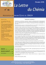
1. SELF-HEALING POLYMERIC SYSTEMSNature has been instrumental in inspiration for innovations and discoveries for human kind sincethe predawn era. One can find a whole range of materials ranging from the har<strong>de</strong>st knownmaterial to innumerable stimuli-responsive systems. These advance complex biological materials areresult of an evolutionary process which started millions of years ago and still continuing. Of all theremarkable features exhibited by these biological systems, the ability to self-heal or regenerate inresponse to damage caused by an external factor is quite intriguing. Organisms like hydra, starfish canregenerate easily even if a large chunk of their body is cut away. In humans, healing process is selfevi<strong>de</strong>ntwhen a small wound is healed over the course of time. Human liver is able to wholly regenerateitself from as less as 25%, <strong>de</strong>monstrating the level of advancement in nature. In biological systems, thehealing process (Figure – 1.1) follows mainly three stages 1 : an inflammatory response to the injurycharacterized by healing material clotting followed by cell proliferation leading to matrix <strong>de</strong>position andin the end remo<strong>de</strong>ling of the matrix. The last two steps generally slow and may span over several months<strong>de</strong>pending upon the extent of injury.Figure– 1.1: Biological route for healing process 11
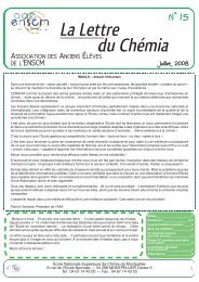
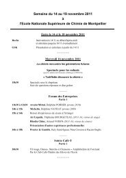
Synthetic engineering materials in general do not have aforementioned healing ability. Most ofthese materials were <strong>de</strong>veloped and optimized by the constant need of more robustness, less cost anddurability. However during the course of utilization, a material encounters various kinds of stressesleading to <strong>de</strong>gradation, internal or external damages and finally a catastrophic failure. Consequently,research community has diverted its attention to <strong>de</strong>velop such smart materials which are able to <strong>de</strong>tectdamages and repair themselves accordingly in an autonomous fashion. Such materials are expected tohave longer life and reduced maintenance and life cycle costs. Different kinds of self-healing approacheshave been <strong>de</strong>veloped for polymers, metals, concretes 2-6 and ceramics 7 with first class showing themaximum <strong>de</strong>velopment related to self-healing. The scope of this chapter and work shall also be limitedto polymers and composites in the same sense.1.1 FRACTURE IN POLYMERIC SYSTEMSPolymers used in engineering domain sustain damage via various external factors like thermal,chemical, biological and respective application related stresses. However, for such materials failurescaused by cyclic fatigue and impact are most important and studied 8,9 . When a crack appears in amaterial, its further propagation insi<strong>de</strong> the material is favored when the amount of energy releasedduring cracking is larger or at least equal to the energy required to create new surfaces on the material 10 .The crack propagation mo<strong>de</strong>ling is often explained using a certain stress intensity parameter K 11,12 I . Thisparameter <strong>de</strong>pends on crack <strong>de</strong>pth, geometry of both crack and material as well as the stress appliedonto the material in case of crack opening type failure (Figure-1.2).Figure– 1.2: Opening failure in a material of mo<strong>de</strong>-I type 13The crack grows when K I reaches a certain critical value, K IQ due to change in the applied stressand geometry of the crack caused by cyclic or monotonic loads. During an impact damage inci<strong>de</strong>nt(consisting of a monotonic load) the extent of crack propagation is related to the maximum stress2
intensity factor (K IMax ) experienced. During fatigue-type damage crack propagation is related to both K IMaxand the change in K I during cycling (K). Either the fractured surfaces of the crack must be resealed orthe growth of the crack must be stunted or checked to effectuate the healing process of the polymer. Anumber of so called extrinsic mechanisms 11,14 are proposed to mitigate the crack growth (Figure– 1.3) 13 .Figure– 1.3: The proposed extrinsic mechanisms for crack growth retardation in a material 13,14 , a) Crack <strong>de</strong>flection,b) Wedging – <strong>de</strong>bris induced crack retardation, c) Wedging – surface roughness induced crack <strong>de</strong>flection, d)Bridging – fiber toughening, e) Zone shielding – microcrack toughening, f) Zone toughening – transformationtoughening, g) Zone shielding – crack field formation, h) Wedging and bridging – fluid pressure induced crackclosureAll traditional and self-healing approaches are based on these mechanisms and generally involvedissipation of energy away from the propagating crack tip via a mechanical change behind the crack tip.1.2 SELF HEALING MATERIALS IN GENERALAn i<strong>de</strong>al self-healing material (polymeric) should have an in-built capability to repeatedly sense,respond and repair from damage it suffered while recovering most of its primal properties within a shorttimeframe. From here, healable polymeric materials can be broadly classified into two classes:Autonomous self-healing materials in which the healing process is triggered by the damage itselfwithout need of any other external stimulus and the materials is able to attain pristine material’sproperties; Non-Autonomous self-healing materials in which healing is triggered and executed in3
esponse to a specific external stimulus (related to inten<strong>de</strong>d application) other than damage. For bothclasses, the most important criteria to fulfill is to have inherent ability to create multiple new bondinginteractions in and around the damage zone by using the components from within their existingstructure 15 . Figure– 1.4 shows the classification of these polymeric systems based on the healingstimulus and chemistry involved that have been discussed in this chapter.Figure– 1.4: Classification of self-healing polymeric systems based on the chemistry involvedSince the domain of applications for polymeric materials is large therefore the primal property differswith each application. Hence it is difficult to ascertain and compare the extent of healing. Also, in mostof the cases, healed material is not able to recover all of the property as was of pristine material. In thatcase, it becomes pertinent to mention the efficiency of the healing method. A basic method proposed 16to <strong>de</strong>scribe the extent of healing can be adopted. The equations used as <strong>de</strong>picted as below:(R) = …….. Eq.(1.1)() = 100 ……. Eq.( 1.2)Above equations have been used explicitly to explain various properties like fracture stress, elongation atbreak, fracture energy, molecular parameters and membrane resistance, etc in different polymericsystems. However it must be noted that the aforementioned equations give information only about that4
particular property. They do not provi<strong>de</strong> information about the extent of recovery of other properties ofthe material during the healing process unless explained separately. The healing efficiencies can becalculated either after healing of a single microscopic crack or after a material has been broken and theparts then separated and rejoined prior to the healing efficiency measurement 15 . Further factors likehealing rate, number of times the material can be healed at the location and the extent of recovery ofpristine properties should also be consi<strong>de</strong>red.1.3 AUTONOMOUS SELF-HEALING POLYMERIC SYSTEMSThese polymeric systems, as <strong>de</strong>fined in the previous section are characterized by their ability toun<strong>de</strong>rgo healing process initiated by the fracture itself. Such materials sometimes also referred asextrinsic self-healing materials rely on two quite comprehensively <strong>de</strong>veloped approaches namely:encapsulation and mechanoresponsive and will be discussed in this section.1.3.1 EncapsulationThe encapsulation approach refers to the embedding of a self-repair fluid filled fibers or capsulesor vesicles within the polymer matrix. In case of damage, the fluid holding reservoir would break therebyreleasing the fluid in the damage plane thus healing the material autonomously. These materials closelymimic healing mechanism observed in nature (Figure-1.1) however unlike biological counterparts; it ismuch simpler and accelerated. This approach primarily has been used for thermoset polymers and theircomposites though applicability has been established for protective coatings and even for packagingfilms 17 .Figure– 1.5: Hollow fiber based repair systems, a) Different configurations consi<strong>de</strong>red, b) Scanning ElectronMicroscopy image of a resin filled fiber 18 .5
The first work based on this approach, reported way back in early 90s consisted of concretereinforced with fibers filled with cyanoacrylate 19 and methylmethacrylate 20 adhesives. The i<strong>de</strong>a was laterreplicated to polymeric system by embedding a two part epoxy crosslinking adhesive filled glass pipettesin a thermoset polymer matrix 21 . The technique was further investigated with different kind of hollowfibers and it was postulated that glass fibers were best suited for controlled fracture providing effectivehealing and also thicker composites were better in performance for healing studies 22 . In another work 18by Bleay et al., a two part system was investigated consisting either both epoxy resin & har<strong>de</strong>nercontained in adjacent fibers or one of them (har<strong>de</strong>ner) dispersed over in microencapsulated form whilethe resin was contained in the fiber embed<strong>de</strong>d within the polymer matrix (Figure – 1.5). Although it wasa onetime repair system however it validated the i<strong>de</strong>a of controlled release of healing agent into apolymer matrix to stop the propagation of a crack, repair it and recover the mechanical properties.An alternative novel approach was <strong>de</strong>veloped by White et al. in 2001, where healing agent wasencapsulated in urea-formal<strong>de</strong>hy<strong>de</strong> microcapsules and embed<strong>de</strong>d in a polymer matrix 23 . Upon crackintrusion, the healing agent would seep into the crack plane from ruptured capsules through capillaryaction where its polymerization takes place, triggered by contact with an embed<strong>de</strong>d catalyst and thusleading to healing of the system (Figure– 1.6a).Figure– 1.6: The autonomic healing concept based on a microencapsulated healing agent embed<strong>de</strong>d in a structuralcomposite matrix containing a catalyst capable of polymerizing the healing agent, a) Cracks forms in the matrixwherever damage occurs thus releasing the healing agent into the crack plane through capillary action which6
contacts the catalyst and un<strong>de</strong>rgoes polymerization thus filling the crack formed, b) Healing effciency is obtained byfracture toughness testing of tapered double-cantilever beam (TDCB) specimens 23 .An almost 75% toughness recovery was obtained for the healed sample in a tapered doublecantilever test where the load was applied perpendicular to the crack plane (Figure – 1.6b).The healing agent used in this approach was the monomer known as dicyclopentadiene whichwould un<strong>de</strong>rgo ring-opening polymerization (ROMP) in the presence of a catalyst (Grubbs’ catalyst) atroom temperature (Figure– 1.8).Figure – 1.7: The Ring Opening Metathesis Polymerization (ROMP) of dicyclopentadiene (DCPD) monomer byRuthenium based Grubbs’ catalystAnother interesting feature of this work was the living nature of the polymer formed within thecrack plane. The reason behind this was the usage of living polymerization catalyst. A direct consequenceof this living nature is that if more monomer is ad<strong>de</strong>d at the place further polymerization would occurgiving the possibility of having multiple healings.Due to novelty of this work and direction it provi<strong>de</strong>d, it is important at this point to discusscertain aspects of this approach. A significant number of parameters need to be consi<strong>de</strong>red andoptimized to obtain good healing.The first parameter is to ensure a so called “sequestration method” 1 for the healing agent andthe catalyst. Various factors i<strong>de</strong>ntified in this method are solubility, volatility, reactivity, viscosity and pHof the healing agent to be encapsulated. Generally a healing agent or catalyst soluble in oil, non-volatile,unreactive to inner wall of the capsule, having low viscosity is consi<strong>de</strong>red i<strong>de</strong>al for this approach thoughthese requirements are not strict as per say.The second parameter is the synthesis procedure of microcapsules and their physico-chemicalproperties. In most of the self-healing work involving encapsulation approach, the microcapsules have7
een prepared from urea-formal<strong>de</strong>hy<strong>de</strong> 24-32 . However other polymers like melamine formal<strong>de</strong>hy<strong>de</strong> (MF)33-36 , recently melamine-urea-formal<strong>de</strong>hy<strong>de</strong> (MUF) 37,38 , polyurethane (PU) 39,40 and acrylates 41 have alsobeen investigated. In a slight modification to this approach, the microspheres were prepared by meltabledispersion encapsulation method in which dispersion of catalyst was carried out in molten wax 42 . Anexcellent toughness recovery was reported with tenfold reduction in catalyst concentration. However anon-linear fracture behavior was also observed for these microspheres. The most common technique forpreparing microcapsules is by miniemusion polymerization technique 43 in which sub-micron oil solublepolymeric phase dispersion is carried out in water phase. During the in situ polymerization process, ureaand formal<strong>de</strong>hy<strong>de</strong> react in the water phase to form a low molecular weight pre-polymer; as the weightof this pre-polymer increase, it <strong>de</strong>posits at the DCPD-water interface. This urea-formal<strong>de</strong>hy<strong>de</strong> polymerbecomes highly cross-linked and forms the microcapsule shell wall. Nanoparticles of pre-polymer then<strong>de</strong>posit on the surface of the microcapsules providing a rough surface morphology that ai<strong>de</strong> in theadhesion of the microcapsules with the polymer matrix during composite processing however it may alsoinhibit the <strong>de</strong>position of the nanoparticles on the UF microcapsule surface thus affecting the wallthickness and ultimately the storability of DCPD for longer duration of time 44 . Barring the thickness of themicrocapsule walls, other features like their surface morphology and size have been found to beinfluenced by manufacturing process variables 27 . While the thickness typically been found to be varyingbetween 160 – 220 nm irrespective of what the process parameters are, the average diameter of themicrocapsules could be varied between 10 – 10000 µm by varying the agitation rate between 200 – 2000rpm. An increased agitation rate would <strong>de</strong>crease the average diameter of the microcapsules. The wallthickness range was found be optimum for robust microcapsules capable of surviving the manufacturingprocess of the polymer while still fragile enough to be ruptured in case of a crack formation 44 .Additionally, a capsule with higher elastic modulus than the matrix was shown to be <strong>de</strong>flecting the crackaway from itself by generating a stress field (Figure – 1.8). Thus to ensure the triggering of the healingprocess, it is of primal importance that the capsule has lower elastic modulus 45 .8
Figure – 1.8: Stress state in the vicinity of a planar crack as it approaches a spherical inclusion embed<strong>de</strong>d in alinearly elastic matrix and subjected to a remote tensile loading perpendicular to the fracture plane 23 .The size of microcapsules further affects the healing efficiency at same weight fraction for agiven crack volume. It was reported that larger microcapsules fared better than smaller due to amountto healing agent present in the polymer sample. A linear <strong>de</strong>pen<strong>de</strong>nce was reported between the amountof healing agent <strong>de</strong>livered to the crack plane and the diameter of the microcapsule for a given weightfraction 46 . Earlier it was found that lower concentrations of smaller microcapsules would impartmaximum toughening to the polymer specimen 47 . With the use of ultrasonification during capsulesynthesis process, a further reduction in the size has been achieved. The lowest average diameterachieved was as small as 220 nm and as big as 1.65 µm. During fracture testing of the specimen, nearlyall the capsules were found to be ruptured and a significant improvement in the fracture toughness pervolume fraction of capsules was observed 24 .The third parameter is the properties of healing agent (monomer)/Catalyst system. The moststudied system so far is Dicyclopentadiene (DCPD), a liquid healing agent/Grubbs’ catalyst, a purplecolored ruthenium (IV) catalyst system. Two isomeric form of DCPD have been i<strong>de</strong>ntified incommercially available monomer (Figure – 1.9) containing more than 95 % of the “Endo” form. In situNMR studies conducted for DCPD reactivity for ROMP showed that the “Endo” isomeric form is lessreactive towards ROMP as compared to “Exo” isomeric form 48 . The reason behind this low reactivity wasreported to be predominant entropic steric interactions. Ethyli<strong>de</strong>ne norbornene (ENB) (Figure – 1.9) isanother potential monomer investigated 37,38,49-53 as an alternative of DCPD. ENB with lower freezingpoint has been found to be more reactive towards ROMP than DCPD 54 . However since the resultingpolymer is linear in case of ENB hence its mechanical properties are inferior to that formed by DCPDpolymerization. This problem was can be circumvented by using blend of these monomers as shown inone study 55 , where a blend of DCPD/ENB (1:3) was found to show highest rigidity than individual9
monomer systems. The addition of ENB not only enhanced the polymerization rate but also reduced theamount of catalyst nee<strong>de</strong>d.Figure – 1.9: Structure of Dicyclopentadiene isomers and Ethyli<strong>de</strong>n Norbornene monomersIn the first work reporting microcapsule encapsulation self healing technique, the catalyst usedwas the first generation Grubbs’ catalyst. Despite good healing observed, the catalyst showed inherentproblems like <strong>de</strong>activation upon exposure to air and moisture, reactivity loss to diethylenetriamine 56,57(curing agent for epoxy matrix), and ten<strong>de</strong>ncy to agglomerate within the polymer matrix leading to<strong>de</strong>lamination. Also its <strong>de</strong>composition starts just above 120 o C in comparison to DCPD’s temperature at170 o C 52,58 . This limitation ren<strong>de</strong>rs this combination’s healing usefulness for polymers requiring higherprocessing or usage temperatures. In most of the studies 44,47,59-63 carried out for DCPD/Grubbs’ catalystssystem, the loading of encapsulated DCPD varied between 10 – 25 wt% while typical catalystconcentration values were 2.5 wt% or 5 wt%. For effective healing to take place, the availability ofactivated catalyst in right amount is of very importance. However this availability has been found to be<strong>de</strong>pen<strong>de</strong>nt upon factors like mixing or<strong>de</strong>r, matrix resin type, type of curing agent, particle size of thecatalyst and the amount of catalyst 44 . Highest healing efficiency was obtained with catalyst particle sizeof 180 – 225 µm while concentrations greater than 2.5 wt% provi<strong>de</strong>d negligible gain in fracturetoughness 44 . A fast dissolution of catalyst is important to obtain a good healing efficiency which wouldotherwise lead to heterogeneous polymerization to exposed catalyst particles locations. Smaller is theparticle size; faster is the dissolution of the catalyst however this brings the problem of more catalystexposure to curing agent mixed in the polymer matrix. The exposure can reduce the overall reactivity ofthe catalyst thus negating the effect of catalyst size and concentration 64 . As reported in an earlier work 65about the ease of handling of Grubbs’ catalyst and preservation of its reactivity by dispersion in paraffinwax, the amine <strong>de</strong>activation problem was circumvented by encapsulating the catalyst in waxmicrospheres of size 50 – 150 µm before dispersing them into the polymer matrix 42 . The catalyst wasfound to retain 69% of its reactivity as well as was uniformly dispersed throughout the epoxy matrixwithout any sign of agglomeration. The system showed improved healing efficiency of 93% atcomparatively very low amount of catalyst loading (0.75 wt%). Wax protected catalyst i<strong>de</strong>a was further10
used for a new epoxy polymer matrix having vinyl ester groups and superior mechanical properties 66 .The resin was cured via free radical polymerization techniques employing amine-peroxi<strong>de</strong> initiator. Asexpected, the wax encapsulated catalyst retained its activity while being exposed to peroxi<strong>de</strong> curingreactions. Larger size microspheres preserved highest catalyst activity 66 . As an alternative to firstgeneration Grubbs’ catalyst, different ruthenium catalysts have also been investigated. In one study 67 ,the first generation catalyst was compared with second generation Grubbs’ and Hoveyda-Grubbs’scatalysts. The three different catalysts were investigated for their ROMP initiation constants, stabilitycuring agents, thermal stability and ROMP reactivity of alternative healing agents. The ROMP initiationconstant of first generation Grubbs’ catalyst was found be lowest in solution while higher in bulk incomparison to second generation catalyst. Hoveyda-Grubbs’ catalyst showed an initiation too fast to bemeasured in both cases. During fabrication of the polymer specimens, the first generation Grubbs’catalyst turns from purple to brown indicating the <strong>de</strong>activation of the catalyst. Second generationGrubbs’ catalyst changed from brown to green but no color change was observed for catalyst of thirdkind. Due to complete <strong>de</strong>activation, no healing was observed for first generation catalyst however<strong>de</strong>spite showing healing activity, no significant improvement was observed in healing efficiency for theother two catalysts. Second generation Grubbs’ catalyst exhibited best thermal stability in self-healingtest at 125 o C.Despite good healing results and tremendous potential of newer generation of Grubbs’ catalyst,the inherent temperature sensitivity, high cost and limited availability of these catalysts prompted thesearch for other cheaper alternatives. As one such cheaper alternative, Tungsten (VI) catalyst system(WCl 6 ) was explored for autonomous self-healing materials for large scale applications 68 . Being a catalystprecursor, WCl 6 needs to be activated for catalytic activity. In this work, WCl 6 was activated with a stablealkylating agent phenylacetylene even in air. Oxidation of WCl 6 also converts it into WOCl 4 which has alsobeen reported as ROMP-active catalyst. Since solubility of catalyst is absolutely necessary forpolymerization to occur, hence to address the insolubility of WCl 6 in DCPD, nonylphenol was also ad<strong>de</strong>das a dissolution agent. A 50% <strong>de</strong>crease was observed in fracture toughness for initially prepared samples,attributed to poor bonding between the matrix and the catalyst. The toughness value increased to 75 %of virgin epoxy when a silane coupling agent was employed. The healing efficiency dropped from 102 %for re-crystallized WCl 6 to 20 % as received but mechanically well dispersed WCl 6 in the polymer matrix.The probable reason for this <strong>de</strong>crease was the exposure of well dispersed catalyst particles to thesurrounding polymer matrix leading to <strong>de</strong>activation of larger surface area. Dispersion after waxprotection gave better efficiency but the corresponding catalyst loading was as high as 7 %.11
Figure – 1.10: Self-healing process based on siloxane and alkoxy siloxane systems, a) Composite consisting ofmicroencapsulated catalyst (yellow) and phase-separated healing-agent droplets (white) dispersed in a matrix(green), b) Crack propagates into the matrix releasing the catalyst and healing agent into the crack plane, c) Thecrick is healed by polymerized PDMS, d-e) Scanning electron microscopy images of the fracture surface, showing anempty microcapsule and voids left by the phase-separated healing agent and a smooth surface microcapsule, f)Average maximum load of self-healed vinyl ester by the method and the corresponding healing efficiencies 39 .Moving away from DCPD/Grubbs’ catalyst system due to their associated high cost and loweravailability, in 2006 a new kind of healing system was introduced by Cho et al 39 . This system was basedon the same healing principle as discussed above however the monomers were changed to hydroxylterminatedsiloxanes and alkoxysilanes while catalysts were changed to organotin compounds. Since thiscatalysts were found to be effective only in the presence of water, hence the proposed healing materialwas radical improvement over the DCPD/Grubbs’ system in which the catalyst was highly susceptible tomoisture. Additionally, the liquid phase healing agent, hydroxyl end functionalizedpoly(dimethylsiloxane) & poly(diethoxysiloxane), could be directly mixed with the polymer matix wherethey would remain as phase separated droplets having size between 1 – 20 µm. This left only theorganotin catalyst (di-n-butyltin dilaurate) to be encapsulated along with a solvent (chlorobenzene). Thesize of the microcapsules could be varied from 50 µm – 450 µm by varying the stirring rate during themicrocapsules formation (Figure-1.10) 39 .The reported healingpolymer system along with a bit higher catalyst loading however the observation is obvious given12
the lower stiffness and fracture toughness of PDMS compared to matrix polymer. In a furthermodification to above work, PDMS was employed as the matrix polymer while containing two differentsets of microcapsules 25 . One set of microcapsules contained a PDMS copolymer with active sites forcrosslinking while the other kind contained a high molecular weight vinyl functionalized PDMS along withplatinum catalyst (initiator capsule). Up to 75% healing efficiency was achieved with 10 wt% resincapsules and 5 wt% catalyst capsules.Encapsulation of epoxy resin in microcapsules as healing agent is also one of the alternativesinvestigated 26,69-71 . However to accomplish healing, a latent har<strong>de</strong>ner has to be incorporated into thematrix. Upon rupture of the microcapsule, the epoxy would seep into the crack and polymerizes due tocontact with embed<strong>de</strong>d har<strong>de</strong>ner thus closing the crack. This approach shares the same advantage asthe PDMS/catalyst system that the healing material generated during the healing process is i<strong>de</strong>ntical asthe matrix material itself chemically. This result in the <strong>de</strong>viation of tear path in the healed sample fromthat of the virgin tear path, resulting in greater than 100 % healing efficiencies. The epoxy/har<strong>de</strong>nersystem, first reported in 2007 71 employed an imidazole-metal complex as a latent har<strong>de</strong>ner. Thesolubility of CuBr 2 (2-MeIm) 4 har<strong>de</strong>ner complex in epoxy ensured a homogeneous distribution all over thematrix and thus capable of curing epoxy at any point in the matrix. The reported diameter range of themicrocapsules was 30 – 70 µm with encapsulated epoxy resin. The incorporation of the har<strong>de</strong>ner and theepoxy microcapsules did not impact the mechanical properties of the matrix as such though fracturetoughness was found to be increased slightly. Using 10 wt% epoxy microcapsules and 2 wt% latenthar<strong>de</strong>ner, an impressive 111% healing efficiency was reported however the approach failed to qualify asa true autonomous healing system. The obvious reason is the inherent need to heat the samplesbetween 130 o C – 170 o C to initiate the curing of the epoxy resin. To make this approach fullyautonomous, the imidazole-metal complex har<strong>de</strong>ner was replaced with low-temperature mercaptanhar<strong>de</strong>ner 34 in conjunction with a tertiary amine catalyst, encapsulated in microcapsules and embed<strong>de</strong>dalong with epoxy filled microcapsules in an epoxy matrix 35 . The microcapsules used for bothcomponents, were based on the melamine-formal<strong>de</strong>hy<strong>de</strong> due to instable nature of mercaptan har<strong>de</strong>ner.The benzyldimethyl amine catalyst was infiltrated into mercaptan filled microcapsules in a secondarystep, since being basic in nature the catalyst couldn’t be incorporated during the microencapsulationprocedure which is performed in acidic medium. A healing efficiency of 104.5% was reported forspecimens containing 5 wt% (2.4 wt % each) capsules at 20 o C (Figure – 1.11a). It was observed thatmaximum healing occurred when the ratio of two microcapsules set is near 1:1. A minimum of 12 hours13
was required to reach healing efficiency beyond 100 %. A novel feature of this work was theachievement of healing at temperature as low as -10 o C with an efficiency of 86% (Figure – 1.11b).Figure – 1.11: Self-healing process based on epoxy/mercaptan system, a) Influence of capsules concentration onfracture toughness of the materials, b) Influence of temperature on healing efficiencies with time.Solvent induced self-healing comprises the earliest known works in the field of self-healing. Firstreported in early 80s, the approach involved the heating of thermoplastic polymers (for example:PMMA) and simultaneous sealing of cracks with solvents like ethanol, methanol and carbontetrachlori<strong>de</strong> 72-77 . The healing mechanism involved wetting of the polymer surface and swelling of thebulk polymer material, which led to reptation and interlocking of the chains across the crack plane torecover mechanical properties of the virgin material and heal the crack. Immersion of polymerspecimens in these solvents reduced the glass transition (T g ) of the polymer, thereby facilitating thehealing procedure to occur at room temperature or slight heating. However due to high <strong>de</strong>gree ofswelling, the healed samples had lower strengths than the original ones. The solvent strategy wascombined with encapsulation technique in 2007 by Caruso et al. in a work where the solvent wasencapsulated and embed<strong>de</strong>d into an epoxy matrix 78 . A significant number of solvents were investigatedand first screened for their healing ability by manually injecting them onto a crack plane of a fracture<strong>de</strong>poxy specimen in reference tests mimicking the <strong>de</strong>livery of solvent to the crack by a ruptured capsule.The study showed a correlation between the healing efficiency and the solvent polarity (Figure – 1.12a).Five aprotic polar solvents exhibited the highest healing efficiencies namely: nitrobenzene, NMP, DMA,DMF, and DMSO. These solvents have dielectric constants ranging from 32 to 47. However, therelationship of polarity with healing efficiency could not be explained. On both extremes of the polarityspectrum, non polar solvents like cyclohexane, hexanes and protic polar solvents like formami<strong>de</strong>, and14
water showed little or no healing. Encapsulation via Urea-formal<strong>de</strong>hy<strong>de</strong> encapsulation and reversephaseencapsulation techniques remained problematic for aforementioned five solvents. The onlysolvent which could be encapsulated with relatively ease wasFigure – 1.12: Solvent based healing system, a) Influence of different solvents on healed peak fracture load, b) Load– displacement curve obtained for short – groove samples 78 .chlorobenzene, encapsulated into microcapsules having average diameter of 160 µm. However themaximum healing efficiency obtained was 82% with 20 wt% capsules loading (Figure – 1.12b).Correspondingly, xylene gave a 38% healing efficiency while that for hexane gave 0%, indicating a<strong>de</strong>pen<strong>de</strong>nce of healing efficiency on the solvent polarity. In a continuation of the above work, furtherenhancements were reported for solvent-based self-healing of epoxy materials 79 . First, in place ofmicrocapsules filled with solvent, a mixture of epoxy resin and solvent was used. This modificationyiel<strong>de</strong>d a complete recovery of fracture toughness after crack propagation. Multiple healing events werealso reported for this system. Second, less toxic solvents including aromatic esters giving efficient healingreplaced more toxic chlorobenzene. A stable shelf-life of one month was also reported for epoxy-solventsystem un<strong>de</strong>r ambient conditions for both chlorobenzene and phenyacetate. Similar encapsulationapproach has been used in case of thermoplastic PMMA thin films where a plasticizer (Dibutylphthalate)was encapsulated in urea-formal<strong>de</strong>hy<strong>de</strong> microcapsules and dispersed into PMMA thin films 80 . Upon,rupture, the DBP is released into the crack where it plasticizes and swells surrounding polymer leading tothe mending of the crack. The use of DBP helps in maintaining the optical properties of the preparedfilms and healed films also. Although no mechanical properties data was presented, the authors claimedto have recovered most of the protective properties of the virgin film along with certain portion ofmechanical properties.15
In addition to above works, some other novel reactive systems have also been investigated inconjugation with encapsulation technique. One of these systems is isocyanate encapsulatedmicrocapsules 40 , which is capable of performing healing in wet or humid conditions. This eliminates theneed to use of a catalyst in the composite material. The isocyanate employed was isophoronediisocyanate encapsulated in polyurethane microcapsules prepared via interfacial polymerization ofpolyurethane prepolymer in an oil-in-water emulsion. The mean diameter of microcapsules and agitationrate followed an inverse power law relationship and isocyanate loss for a half year period was less than10 wt%. In a more recent similar work 81 , microcapsules containing a reactive amine with potentialapplications in self-healing polymers were prepared by interfacial polymerization of an isocyanate and anamine stabilized by an inverse pickering emulsion. The microcapsules were successfully isolated, dried,and redispersed in epoxy. Upon rupture, the capsules released the core material thereby able to cure theepoxy to form a polymer film. Click-chemistry has also been presented as a potential chemistry forhealing materials. In one such work 31 , a liquid azido-telechelic three-arm star poly(isobutylene) polymerand trivalent alkynes were encapsulated into micron-sized capsules and embed<strong>de</strong>d into a high molecularweight poly(isobutylene) matrix. Using (Cu(I)Br(PPh 3 ) 3 ) as low temperature catalyst for the azi<strong>de</strong>/alkyne-"click"-reaction, crosslinking of the two components at 40 o C was observed within 380 min and as fast as10 min at 80 o C. Significant recovery of the tensile storage modulus was observed in a material containing10 wt% capsules. Though promising, the approach still relies on the incorporation of a catalyst which isair sensitive, thus losing its activity over the surface of the material. Living polymerization techniques likeATRP 82 and RAFT 83,84 have also been explored where liquid monomer (glycidyl methacrylate) isencapsulated in microcapsules. Again, these systems though attractive, still posses inherent limitations.In case of ATRP, being air-sensitiveness of the catalysts used, the surface healing cannot occur as theyget <strong>de</strong>activated being in contact with humidity. Also, the metal ions are reported to accelerate the<strong>de</strong>gradation of the material. Additionally, since the polymerization needs heating well above roomtemperature, hence it cannot be called an autonomous healing system. The RAFT approach althoughskips the problem of <strong>de</strong>activation but still requires heating of the matrix for effective healing hencecannot be termed un<strong>de</strong>r autonomous healing systems. In place of microcapsules, use of carbonnanotubes as reservoirs has also been proposed via simulation studies 85,86 which will not only givehealing ability but also boost mechanical and electrical properties for advanced applications.1.3.2 Microvascular NetworksThe microvascular approach is another novel approach which draws maximum inspiration fromnature to create most biomimetic synthetic material. Although this methodology shares basics with the16
hollow glass fibers and encapsulation techniques discussed in previous section, a striking advantagewhich differentiates it from these two techniques is the ability to heal at the same point multiple times.This healing multiplicity originates from the presence of an interconnected network of hollow capillariesfilled with healing agent insi<strong>de</strong> the polymer matrix. This healing system closely resembles the healingmechanism evi<strong>de</strong>nt in humans, animals and even certain plants. For example, in human body (or ananimal), blood circulates in an intricate network of arteries, veins and capillaries of varying diameter in aclot-free fluid state. When damage happens at a particular point, a localized solid clot of blood is createdto fill the wound (Figure – 1.13). Designing of an efficient microvascular system similar to that inbiological systems, it is primordially important to consi<strong>de</strong>r various factors like shape of vesicles, theirdimensions, orientation, 3D spatial arrangement. In such a scenario, Murray’s law can be consi<strong>de</strong>red,according to which the cube of the radius of the parent vessel should equal the sum of the cubes of theradii of the daughter vessels. It was postulated that minimization of associated energetic cost withoptimum transport flow in a circulatory system could be achieved by maintaining this ratio 87 .Figure – 1.13: Microvascular network of blood vessels and capillaries beneath the skin which supply the requiredmaterials for healing in case of damage to the skin.A number of efficient network architectures have been proposed like a network of few largechannels having large number of smaller sub-channels 88 , looped channels 89 , grid network 90,91 , dualchannels network 92 for optimum performance. In general, utilization of two segregated type of channelshas been consi<strong>de</strong>red to be an optimal approach for the realization of vascular healing system. Un<strong>de</strong>rwhich, the main supply channels should be robust and strong enough to remain undamaged in case ofmechanical impact thus maintaining the structural integrity of the material while the smaller channelsshould be capable of rupture and releasing the healing agent into the ruptured site 92 . Leakage ofprincipal supply channel, closing of smaller channel due to cured healing agent, failure of smaller channelto rupture, <strong>de</strong>gradation of healing agent and its improper cure are some of the additional parameters17
that have been i<strong>de</strong>ntified to be taken into consi<strong>de</strong>ration while <strong>de</strong>signing materials based onmicrovascular approach 93 . Based on genetic algorithms, a mo<strong>de</strong>ling and optimization scheme wasprepared for <strong>de</strong>signing of 2D and 3D microvascular networks 94 . Various parameters like flow efficiency,homogeneity, network redundancy, network topology, microchannel diameter and void volume fractionwere consi<strong>de</strong>red. The results showed that the addition of diagonal microchannels in the templateimproves flow efficiency, specifically at low values of the void volume fraction.Figure – 1.14: a) Self-healing epoxy composite structure based on microvascular approach, b) Propagation of crackstowards the microchannel openings at the interface of the composite, c) Healed cracks with excess healing agentoozed out on the surface 95 .In a first practical work reported by Toohey et al. in 2007 <strong>de</strong>monstrating the above approach,epoxy composite materials were prepared and corresponding healing efficiencies were measured innumber of healing cycles 95 . The work employed a 3-dimensional grid network substrate having 200 µmchannels filled with dicyclopentadiene and embed<strong>de</strong>d into a 700 µm epoxy coating which containeddispersed Grubbs’ catalyst (Figure – 1.14). The interconnected nature of the channels was utilized toreplenish the monomer reservoir enabling the healing of sample repeatedly up to 7 consecutive cycles.The system provi<strong>de</strong>d a 70% peak healing efficiency with 10 wt% catalyst in the top coating. It wasremarked that the amount of catalyst (being a limited factor for a given sample) dictated the number ofhealing cycles that could be performed rather than healing efficiency for that sample. In following years,the number of healing cycles was augmented to 16 by using a two-part epoxy-amine healing chemistry18
with dual isolated networks, holding each healing component 96 . A peak healing efficiency of 60 % wasachieved. Although the system <strong>de</strong>monstrated clear advantages over DCPD/catalyst system, issuesrelated to effective mixing of healing agents with successive healing cycles still persisted thereby limitingthe maximum number of healing cycles that could be achieved.In a parallel work 97 published in 2007 by Williams et al., a microvascular-containing mechanicallystimulated healable composite with sandwich structure was presented. The study found negligibleinfluence of the network on the innate static mechanical properties of the host panel. The releasedhealing agent (premixed epoxy/har<strong>de</strong>ner) from ruptured channels was found to fill and repair the voidresulted due to impact damage to the specimen leading to a full recovery of mechanical properties in asingle healing cycle 97 . In a follow on study 98 consisting of dual network containing each componentseparately, showed significant recovery.. In more recent work 99 , dual complex and isolated 3-dimensional interpenetrating networkshave been prepared to facilitate better stoichiometry and mixing at the damage point thus increasing themaximum number of healing cycles to more than 30 times. In a further refinement 100 , a ternaryinterpenetrating network has been prepared where the third network is ad<strong>de</strong>d to act as a conduit forcirculating a temperature-controlled fluid that rapidly heats the locally damaged region leading to asharp reduction in the time required for mechanical property restoration. The characteristic healing timeis reported to be reduced by an or<strong>de</strong>r of magnitu<strong>de</strong> by employing a third interdigitated microvascularnetwork enabling in situ thermal regulation within the epoxy coating/substrate architectures.1.4 NON-AUTONOMOUS SELF-HEALING POLYMERIC SYSTEMSThe autonomous healing polymer systems discussed so far have been remarkable for theirperformance and healing abilities for the particular applications they have been <strong>de</strong>signed for. However<strong>de</strong>spite their novelty, they still suffer from limited number of possible healing cycles and limitation toonly certain type of polymer matrix. These limitations have prompted researchers to <strong>de</strong>velop otherstrategies to obtain self-healing properties. The non-autonomous self-healing polymer materials rely onthese strategies where the healing mechanism is triggered by certain stimulus, often integral part of theapplication for which the material has been <strong>de</strong>signed. These materials are sometimes referred to as“intrinsic self-healing materials” because the inherent chemical nature of the polymer matrix is sufficientenough to un<strong>de</strong>rgo the healing process, negating the need of adding any external healing agent. Thisintrinsic nature imparts these materials a theoretical ability to heal unlimitedly though it comes as atra<strong>de</strong>-off for autonomic healing, relatively lower healing efficiency or low mechanical properties. In this19
part of the chapter, these materials have been discussed based on the nature of bond chemistry theypossess and the stimulus they require for the initiation of the healing process.1.4.1 Dynamic Non-Covalent Bonding1.4.1.1 Supramolecular ChemistryThe foremost dynamic non-covalent bond chemistry is represented basically by supramolecularchemistry involving non-covalent bonds such as hydrogen bonding, metal-ligand complexat – interactions which are reversible by nature and have been studied extensively 101 . Potential advancedfunctional applications for these interactions have been recently discussed 102,103 . Although reversible innature, this dynamism however comes as a bargain with lower mechanical properties as compared tothe materials with covalent bonding. To circumvent this problem, the number of such interactions wasincreased to get more robust materials in the form of linear polymer and reversible networks,copolymers 104-107 . These materials exploited the directional and cooperative effects of quadruplehydrogen bonding exhibited by 2-ureido-4-pyrimidone (UPy) functionalized monomers (Figure – 1.15).Figure – 1.15: Synthesis of biomimetic polymer prepared from, a) Assembly of 2-ureido-4-pyrimidone motifs havingquadruple hydrogen bonding, b) The proposed mechanism of healing 107 .In 2008, a first supramolecular chemistry based material with <strong>de</strong>cent mechanical properties andself-healing ability was introduced by Cordier et al 108 . It exhibited rubber like properties and harnessedthe directionality and reversibility of hydrogen bonds as a tool to possess self-associated chains forminga network. The material was prepared from low molecular weight fatty di- and triacids functionalizedwith amido imidazolidones moieties which would then be mixed with urea <strong>de</strong>rivatives in such a fashion20
so as to have significant directional hydrogen bonding leading to network without crystalline regions(Figure – 1.16a).Figure – 1.16: Supramolecular chemistry based rubber, a) Mixture of oligomers obtained by reacting urea withcon<strong>de</strong>nsed product of di- and triacids and diethylene triamine b) Stress-Strain curve obtained for the rubber, c)Creep recovery experiments conducted for the rubber 108 .The polymeric material with 11 % do<strong>de</strong>cane plasticization exhibited rubber like properties with strain atbreak exceeding 500 % while a residual strain of less than 5 % after elongated to more than 300 %(Figure – 1.16b,c). The other remarkable feature of this material making it relevant to the currentdiscussion was its excellent self-healing ability and efficiency with a little mechanical stimulus. Themechanical stimulus was nee<strong>de</strong>d to bring the cut faces in contact with each other for the healing processto take place. When cut into two complete separate pieces, the material would mend itself completelywith contact time of 15 minutes with elongation at break near 200 %. In elaborate series of experiments,it was shown that with longer contact time led to better recovery and longer is the elapsed time beforebringing the cut faces together, lower is the recovery of strength (Figure- 1.17a,b,c). Another importantfeature of the healing ability of this system was its site specificity, i.e. healing could occur only betweentwo fractured surfaces in contact with each other.21
Figure – 1.17: Self-healing of the rubber at roome termperature, a) Stress – Strain curves until break obtained forhealed sample at 40 o C, b) Stress – Strain curves obtained at 20 o C, c) Stress – Strain curves obtained for healedsamples at 20oC but the two cut faces were joined after 18 hours time gap 108Metal-ligand coordination bonding is another approach that has been explored for thepreparation of self-healing polymer systems. A preliminary work 109 in 2007, hybrid polymer gels wereprepared with covalent cross-links creating a permanent, stiff network onto which reversible metal–ligand coordinative cross-links were ad<strong>de</strong>d. It was shown, that reversible metal–ligand interactions bearmechanical stress within the hybrid gel thereby relieving the permanent network from stress. Uponremoval of stress, these interactions would reform and reinstate the original strength of the material.Taking cue from nature, another novel self-healing polymer system has been proposed which mimics thecatechol – iron complexation exhibited by mussel tissue. The rheological analysis of the system showednear covalent stiffness (G’) of catechol-Fe 3+ cross-linked networks at high strain rates proving that at a pHhigh enough to ensure good cross-linking; these transient coordination bonds can provi<strong>de</strong> significantstrength to bulk materials. Additionally, the catechol-Fe 3+ cross-linked gels reestablished their stiffnessand cohesiveness within minutes after through restoration of broken catecholato-Fe 3+ cross-links thusshowed near 100 % self-healing.– been exploited to obtain robust self-healing materials.In a first example of its kind 111 , burattini et al prepared films from thermoresponsive polymer blends- electron-poor receptor sites along itsbackbone and a siloxane polymer having p-electron-rich pyrenyl end-groups (figure- 1.18a). The systemexhibited a rapid and reversible complexation in solution while solid state thermohealable22
characteristics, due to presence -electron-rich and -poor receptors. Manual cuts ma<strong>de</strong> onto the filmswere shown to be healed completely at 90 o C within a short time while at 115 o C, healing was too fast tobe observed (Figure – 1.18b,c,d).Figure – 1.18: Self-healing system based on – olyimi<strong>de</strong>and siloxane polymer bearing pyrenyl end groups, b-d) Unhealed and healed films at 30 o C, 92 o C and 115 o Crespectively 110 .In a further improved work, the authors capitalized on both interpolymer hydrogen bonding and– system exhibited a nanophase separted morphology with well contrasted two different domains. Theauthors reported a reproducible regain of more than 95% of the tensile modulus, 91% of the elongationto break, and 77% of the modulus of toughness of the pristine material for fractured samples healed at100 o C.1.4.1.2 IonomersPolymers consisting of upto 15 % of ionic content in their structure are classified as ionomers. Beingthermoplastic in nature, these polymers contain carboxylic acid moieties as pendant groups which caneither be in partially or completely neutralized state with either a metal or quaternary ammonium ions.Given the dynamic nature of the ionic bonds, it is not surprising that these polymer systems beenexplored recently for the preparation of self-healing materials. One of the most studied ionomers forself-healing application are based on poly(ethylene-co-methacrylic acid) (PEMAA). This ionomer is23
commercialized un<strong>de</strong>r tra<strong>de</strong>names; Nucrel® having 5.4 mol% methacrylic acid, Surlyn® having 5.4 mol%methacyrlic acid but neutralized by metal ion in varying percentages. Both of these ionomers haveshown self-healing behavior upon projectile impact, especially Surlyn® which shows an almostinstantaneous healing. Earlier it was postulated that the healing phenomenon observed in theseionomers is due to their inherent thermally responsive ionic linkages. However this reasoning does notexplains albeit small healing observed in case of Nucrel® which does not contain any ionic aggregates.Furthermore, the projectile puncture in these ionomers was circular in nature with diameter inmillimeters. Therefore, while reptation motions responsible for chains interdiffusion in case of fracturedsurfaces in contact with each other, it is impossible for them to initiate large scale motions required tobring the surfaces together to heal the circular perforation. A later work 112 on the same ionomersshowed that instead of ionic content, it is the presence of an ionic functionality (in the form of acidgroup) that is crucial for the healing process. The authors found that the incorporation of acid groups inthe polymers, imparted thermoresponsive hydrogen bonding and unique viscoelastic response whichwere responsible for the promotion of the healing process. In follow on thermal studies 113 , it was foundthat healing mechanism is strongly <strong>de</strong>pen<strong>de</strong>nt upon the sharp increase in temperature at the puncturepoint after projectile impact however higher temperatures did not favored the healing process. Theshape of projectile was also found to be important parameter for the healing response with pointedprojectiles giving better results than blunt ones. In contribution to above findings, similar ballisticstudies 114 combining a modified testing method 115 showed that while the outer impact regions exhibitductile/elastic behaviour, the inner regions to the impact cavity exhibit elastomeric and viscousbehaviour. The presence of ionic clusters imparts various properties from elastic, elastomeric and thenmolten behavior at different temperatures and thus playing a critical role during high-energy impact(Figure – 1.19). Additionally, healing cycles up to 6 were performed <strong>de</strong>monstrating the inherent natureof healing based on the chemical structure and morphology of the polymer system. Some more recentexamples 116,117 using ionomers inclu<strong>de</strong> their blends with ethylene-co-vinyl alcohol copolymer (EVA) an<strong>de</strong>poxidized natural rubber. Although in these works, healing efficiency has not been mentioned explicitly,nevertheless ionomers based materials can be consi<strong>de</strong>red highly efficient and completely autonomous interms of healing given the rapid closure of hole created by very fast impact.24
Figure – 1.19: Self-Healing in ionomer Surlyn 8940® upon projectile induced damage at, a) 20 o C, b) 50 o C, c) 90 o C, d)130 o C, e) 170 o C, f) 210 o C 1181.4.1.3 Molecular InterdiffusionThe concept of molecular interdiffusion for self-healing was proposed in 1980s when a numberof works on crack-healing were published for PSAN-PMMA 72 , PSAN 119 , PET 120,121 , Polyami<strong>de</strong>s 122 , PS-PVPE 123 , PS-PPO 123 and carbon fiber reinforced PEEK composites 124 . The healing observed in thesepolymer systems was attributed to molecular interdiffusion across the interface, facilitated by closecontact between two surfaces at a temperature slightly higher than glass transition (T g ). At elevatedtemperatures, molecular chains entanglement would ensue the interdiffusion process leading to a swiftdisappearance of the interface and an increase in mechanical properties along with completion of thehealing process. All of these works involved heating of specimens at temperatures above the T g of thepolymer system, usually varying between -50 o C to +100 o C un<strong>de</strong>r certain pressure. Depending upon thekind and extent of fracture, temperature, pressure, sample geometry, the reported healing times wouldvary from few minutes to as long as years. In or<strong>de</strong>r to explain this healing phenomenon viainterdiffusion, various mo<strong>de</strong>ls were consi<strong>de</strong>red; notably the reptation mo<strong>de</strong>l of chain dynamics 125,126 andlater a five stages mo<strong>de</strong>l (Figure – 1.20) explaining the execution healing process in terms of surfacerearrangement, surface approach, wetting, diffusion and randomization 16 . A mathematical microscopictheory was also presented to further explain the diffusion and randomization stages 127 . It was conclu<strong>de</strong>dthat due to large presence of small chain segments (formed due to chain scission) at the fracturedsurfaces, the diffusion phenomenon is very different from that when two pieces of the same polymer are25
joined together at temperature higher than the T g since the latter has larger flat segmental distribution.Due to unavailability of a universal method to obtain the healing thereby varied healing times along withnon-autonomous nature of the process, motivation for this approach almost en<strong>de</strong>d by the beginning of1990s. However the theory of interdiffusion and the mo<strong>de</strong>ls presented have been used to study and<strong>de</strong>sign encapsulation and microsvascular based healing approaches.Figure – 1.20: Mechanisms involved in self healing via molecular interdiffusion.1.4.2 Dynamic Covalent BondingMuch like dynamic non-covalent bonding, dynamic covalent bond chemistry has also been extensivelyexplored. Polymers incorporating these bonds do not suffer from low mechanical properties as theircounterparts with non-covalent bonds. However again, this comes with less impressive self-healingability and lower healing efficiencies. Moreover, most of these systems require a particular stimuli likeheat, light, mechanical stress, pH fluctuations specific to the inherent dynamic chemistry of the material.In most of the cases, these materials have been <strong>de</strong>signed in such a fashion that the required stimulus forthe healing is encountered as a part of the sought application. Nevertheless, human intervention is stillrequired in some way or another; hence these systems are categorized as non-autonomous self-healingsystems.1.4.2.1 Diels-Al<strong>de</strong>r Chemistry26
The diels-al<strong>de</strong>r cycloaddition reaction was discovered in 1928 by Otto Diels and Kurt Al<strong>de</strong>r (Figure– 1.21). The beauty of this reaction lies in its ability to form C – C bonds with little or no heat application.However the feature that makes it even more important for synthesis of self-healing materials is itsthermal reversibility, also known as reversible diels-al<strong>de</strong>r reaction (rDA). Generally the rDA reactiontakes place at temperature higher than 100 o C and gives back the reaction precursors.Figure – 1.21: The Diels-Al<strong>de</strong>r reactionA large number of publications have been published concerning the synthesis of polymersystems employing rDA chemistry, but their applicability for self-healing application and relevant datahas been reported quite lately. In general, most of such polymer systems either incorporatedienophile/diene as a pendant groups to the backbone chain or the backbone chain itself is formed dueto consecutive DA reactions between functionalized monomers. The Furan/Maleimi<strong>de</strong> combination hasbeen the most explored DA-rDA chemistry system for the fabrication of thermally self-healed polymersalthough other dienophile/diene combinations have also been explored. In 1969, the earliestknown work as a patent on the synthesis of a thermally reversible polymer incorporatingFuran/maleimi<strong>de</strong> moieties was reported. This was followed by a series of pioneering works 128-130 , inwhich these moieties were incorporated as pendant groups onto the polymer chains (Figure – 1.22).Figure – 1.22: Reversiblly crosslinked polymer via Diels–Al<strong>de</strong>r cycloaddition reaction between pen<strong>de</strong>nt furan andmaleimi<strong>de</strong> moieties 129 .27
Inspired by these findings, the first thermally remendable polymer system based on DA-RDAchemistry was reported in 2002 131 by Chen et al.. A transparent and highly crosslinked solid polymer wasprepared by diels-al<strong>de</strong>r reaction between tris-maleimi<strong>de</strong> and a tetra-furan (Figure – 1.23a). The polymershowed significant mechanical properties comparable to that of contemporary epoxy systems. Thehealing studies were conducted by completely fracturing the specimen followed by heating (90 o C –120 o C) and cooling cycles and structural analysis by solid state C-NMR spectroscopy. The system wasfound to be able to heal multiple times although the healing efficiency was reported to be only 57 %(Figure – 1.23b)., the reason of which was attributed to the complete failure of the specimen leading topoor interfacial match-up between separated pieces.Figure – 1.23: Diels-Al<strong>de</strong>r reaction based self-healing, a) Highly crosslinked polymer formed from trimaleimi<strong>de</strong> andtetrafuran, b) Stress-Strain curve obtained for the healed specimen with only 57 % efficiency 131 .In a follow on work 132 , several improvements were ma<strong>de</strong> to obtain a better healing efficiency.The new polymer was prepared in solvent-free conditions using a lower melting point bismaleimi<strong>de</strong> inplace of previous tris-maleimi<strong>de</strong>. A better <strong>de</strong>signed sample geometry for mechanical strength testingprevented complete specimen failure which permitted to have higher healing efficiencies of 80 % for firstcycle while 78 % for second healing cycle. A series of works 133-138 have since been reported using theabove approach to prepare thermally healable polymers and investigate their healing properties. Giventhe high crosslinking nature of these polymers and good mechanical strength thus obtained, themultifunctional furan/maleimi<strong>de</strong> <strong>de</strong>rivatives have also been explored for generating polymers forstructural applications. In one of such recent works 139,140 , carbon fibre reinforced polymer compositehave been prepared using tetrafuran/bismaleimi<strong>de</strong> based highly crosslinked polymer. In parallel to28
above approach, the pendant group approach has also been extensively explored for the fabrication ofthermally self-healing polymers. Most of the examples 140-142 are based on the incorporation of furanmoiety as pendant groups (Figure – 1.24a) onto a thermoplastic or a thermoset polymer while a bis- ortrismaleimi<strong>de</strong> (Figure – 1.24b) compound is ad<strong>de</strong>d as reversible crosslinking agent. Additionally, directpolymerization of furan based methacrylates with other methacrylates using atomic transfer radicalpolymerization to obtain controlled molecular architectures has also been performed 143,144 . In a recentwork, a recyclable furan functionalized polyketone thermoset, crosslinked with bismaleimi<strong>de</strong> waspresented 145 . The reversible gelation as a function of temperature was used as an indicator for DA andrDA reactions <strong>de</strong>monstrating the thermal reversibility of the system. The recyclability of the system wasproved by grinding a fractured sample and fabricating a new sample from it. The new sample performedas similar as the pristine sample in mechanical tests which led the authors to claim a 100 % healingefficiency in an otherwise different context.Figure – 1.24: Thermoreversible complex architectures ma<strong>de</strong> reaction of, a) Hydroxyethylcellulose furoate acetatewith, b) Bismaleimi<strong>de</strong> to form, c) Crosslinked polymer having flexible structure with liquid crystalline properties 141Besi<strong>de</strong>s furan/maleimi<strong>de</strong> combination, there are also other compounds like dicyclopentadiene 146-148 and anthracene 149 which have been used recently to fabricate thermally reversible polymers. Theadvantages of dicyclopentadiene is its cyclic nature which provi<strong>de</strong>s a favorable s-cis conformation forDiels-Al<strong>de</strong>r reaction and its ability to self-react to form DA adduct ren<strong>de</strong>ring the need to use maleimi<strong>de</strong>as a dienophile. For instance, in one example, a biscyclopentadiene end-functionalized PMMA wassynthesized and then crosslinked with a trifunctional pyridinyl dithioformate compound via hetero-DAreaction 150 (Figure – 1.25). Although no healing data in terms of mechanical properties or visual healingwas presented, the so called “bonding” at room temperature in 10 minutes and “<strong>de</strong>bonding” at29
temperature greater than 80 o C in less than 5 minutes of the system was <strong>de</strong>monstrated by size exclusionchromatography and ultra-violet spectroscopy.Figure – 1.25: Thermoreversible crosslinked Poly(methyl methacrylate) network formation via hetero Diels-Al<strong>de</strong>rreaction 150 .The high temperatures associated with rDA reactions may sometimes generate un<strong>de</strong>sirablebyproducts due to <strong>de</strong>composition of the polymer or any other reactant present in the system. Also asignificant emphasis has been put towards the <strong>de</strong>velopment of room temperature self-healing systems;therefore it is <strong>de</strong>sirable to reduce the required temperature for rDA reaction as low as possible tominimize the need of energy for the healing process and if possible a complete replacement of heatingprocedure itself. In view of this constraint, use of ultrasound as a tool to facilitate rDA reaction has beenproposed recently. In this work, poly(methyl acrylate)s (PMAs) of different molecular weights wereprepared from a Diels-Al<strong>de</strong>r adduct of maleimi<strong>de</strong> with furan containing two polymerization initiators.When subjected to ultrasound at 0 o C, the authors <strong>de</strong>monstrated the occurrence of rDA with gelpermeation chromatography (GPC), ultra-violet visible spectroscopy and chromophore labeling of theliberated maleimi<strong>de</strong> and furan moieties. However the no rDA reaction was observed for polymers withmolecular weight greater than 60 KDa and lesser than 20 KDa. Similar results were obtained foranalogous polymers that were prepared from a cycloaddition adduct initiators of maleimi<strong>de</strong> withanthracene. Driven by the same constraint, new class self-healing polymer films have been successfullyprepared by capitalizing over room temperature dynamic Diels-Al<strong>de</strong>r chemistry 151 . In this novel work byReutenauer et al, self standing thin films were casted from a mixture of bis(fulvene) andbis(tricyanoethylenecarboxylate) dynamers (Figure – 1.26a). To <strong>de</strong>monstrate the self-healing ability, thefilm was cut into two pieces and then the two pieces were pressed together with some overlapping. Inless than 10 seconds, the pieces could no longer be separated (Figure – 1.26b). This is in contrast withthe behavior shown by self-healing supramolecular elastomer which showed healing only between two30
freshly cut surfaces. The reason behind the all surface healing feature has been attributed to the abilityof the dynamers to constantly create new chain ends and form new connections.Figure – 1.26: Diels–Al<strong>de</strong>r chemistry used to prepare, a) Reversibly cross-link fulvene functionalized glycol-basedpolymers with a cyanfumarate di-linker at room temperature, b) Room temperature healable film ma<strong>de</strong> from thecrosslinked polymer 151 .1.4.2.2 Sulfur ChemistrySulfur chemistry is another emerging strategy for inducing self-healing ability in a polymericsystem. The interesting feature which makes disulfi<strong>de</strong> bonds important for this application is theircleavage un<strong>de</strong>r reducing conditions to give thiol groups which revert back to disulfi<strong>de</strong> linkage in oxidizingconditions. Hence it is obvious from above feature that polymers consisting disulfi<strong>de</strong> bridges can bereversibly crosslinked by effectively using reduction-oxidation conditions. Some notable workscapitalizing above this chemistry inclu<strong>de</strong> the very first example of a reversibly crosslinkable polyoxazolinehydrogel with disulfi<strong>de</strong> bonds 152 , ATRP <strong>de</strong>rived polystyrene having disulfi<strong>de</strong> bridge in the middle 153 , ATRP<strong>de</strong>rived poly(ethylene glycol diacrylate) m -co-(poly(butyl acrylate)-b-poly(SS)) n star copolymers 154 (Figure –1.27).31
Figure – 1.27: Sulfur chemistry based synthesis of, a) Reversible cross-linked star polymers, b) Reduction andOxidation of SH/SS-Functionalized Star Polymers 154 .In a slight different approach 155 , a polymeric network was prepared from pentaerythritol tetra(3-mercaptopropionate) and triethyleneglycol divinyl ether along with a comonomer and instead of usingreduction – oxidation for reversible crosslinking, light was used an agent for trigerring the cleavage of theallyl sulfi<strong>de</strong> linkages. This photoinduced cleavage led to plasticity, actuation, and equilibrium shapechanges without residual stress into the material.Although none of these works reported any data regarding self-healing property, the relativeease of reversibility (especially in case of photoinduced cleavage) of these systems exhibited pointstowards the capability of thiol chemistry for a robust self-healing system in applications like functionalcoatings. In one such instance, poly(n-butyl acrylate) grafted star polymers were prepared by chainextension ATRP from cross-linked cores comprised of poly(ethylene glycol diacrylate). These polymerswere further used as copolymerized with bis(2-methacryloyloxyethyl disulfi<strong>de</strong>) (DSDMA), imparting32
disulfi<strong>de</strong> reversible cross-links (S-S) at branch peripheries (Figure – 1.27). The S-S cross-linked polymerswere then cleaved un<strong>de</strong>r reducing conditions to form thiol (SH)-functionalized soluble star polymers,which were then <strong>de</strong>posited on silicon wafer substrates and oxidized into insoluble S-S re-cross-linkedfilms. The self-healing of prepared polymer films was studied by continuous atomic force microscopy(AFM) imaging of cuts micromachined with the AFM tip and by optical microscopy. The re-cross-linkedstar showed a rapid spontaneous self-healing behavior, with the extent of healing <strong>de</strong>pen<strong>de</strong>nt on theinitial film thickness and the width of the cut. The self-healing behavior observed for this sample wasattributed to the regeneration of S-S bonds via thiol - exchange reactions. Another recent work utilizingthermal disulfi<strong>de</strong> exchange chemistry instead of disulfi<strong>de</strong> redox chemistry and explicitly reporting selfhealingability involved epoxy resin crosslinked with a tetra thiol based crosslinker. The material showedrubbery behavior due to lower T g and healing experiments were performed by making a knife cut intothe sample followed by heating at 60 o C for certain time without application of any force. The initial cut inthe sample disappeared completely after 1 hour at 60 o C as observed with microscopy (Figure- 1.28a).Additionally, the mechanical properties in terms of elongation at break were found to be fully restored atthis temperature and in general better healing was observed with longer healing time and higherconcentration of sulfi<strong>de</strong> crosslinker. The system exhibited impressive healing efficiency in multiplehealing cycles as evi<strong>de</strong>nt by the very little change in elongation at break values observed for threesuccessive healing cycles.Figure – 1.28: Self-healing material based on reshuffling trithiocarbonate units, a,b) General mechanism ofreshuffling un<strong>de</strong>r UV radiation, c) Preparation of a cross-linked polymer by RAFT copolymerization of Butyl Acrylate,d) Photographs of cross-linked polymers in repetitive self-healing reactions un<strong>de</strong>r UV irradiation in acetonitrile33
A different kind of sulfur chemistry has also been investigated in the form of trithiocarbonates,which are capable to un<strong>de</strong>rgo reshuffling reactions when irradiated with UV light (Figure – 1.28a). Achemical simulation based proof of concept study 156 was reported on this in 2010 followed by practicalexamples in the following years 157,158 . In the most recent example based on this approach, self healingpolymer gels were prepared from reversible addition fragmentation transfer (RAFT) copolymerization ofn-butyl acrylate and a trithiocarbonate cross-linker to obtain Poly(n-butylacrylate) (PBA), a polymer witha low T g value ( 50 o C) having high chain mobility at room temperature (Figure – 1.28b).Healing was reported in terms of joining of pieces of monolithic polymer gel (in acetonitrile) whenirradiated with UV light un<strong>de</strong>r nitrogen atmosphere with 10 g wt pressure with time duration varyingbetween 4hrs – 12 hrs. The tensile modulus obtained for the healed monolith was 65±11 kPa while thatfor pristine monolith was 69±6 kPa indicating an almost complete recovery of mechanical strength.1.4.2.3 Miscellaneous ChemistriesIn addition to above discussed classical dynamic covalent chemistries, some novel chemistrieshave also been <strong>de</strong>monstrated of their potential for the synthesis of self-healing materials.Figure – 1.29: Mechanoresponsive chemistry based Self-healing, a) Dog bone shaped specimens of poly(methacrylate) (PMA) which changes from being colorless (spiropyran) to colored (merocyanine), b) Sample of PMAstretched until broken with corresponding change in color, the yellow colored controlled sample does not containthe mechanoresponsive moieties, c) Optical photos of PMMA beads containing mechanophore moieties un<strong>de</strong>rcompression, d) Threshold stress and yield stress remain coinci<strong>de</strong>nt for PMMA beads as a function of strain rate 159 .34
In first such example 159 by Davis et al., mechanoresponsive chemistry 160 was employed for<strong>de</strong>monstrating mechanical force <strong>de</strong>pendant color change in mechanophore-linked poly(methylacrylate)(PMA) elastomers and mechanophore cross-linked poly(methyl methacrylate)(PMMA) glassypolymer specimen. The spiropyran mechanophore would un<strong>de</strong>rgo a stress-induced 6- electrocyclic ringopeningreaction to give merocyanine form accompanied by a stark change in color (Figure – 1.28a). In aseries of tensile stress tests conducted for mechanophore linked PMA and compression tests formechanophore crosslinked PMMA beads, the authors were able to successfully visualize threshold stressfor the specimens before failure (Figure – 1.28b). In case of PMMA bead compression tests (Figure1.29c), that the threshold strain was found to be constant irrespective of strain rate while both yieldstress and threshold stress increased linearly thus indicating that the mechanochemical reaction in thebulk polymer to be a strain-activated rate process(Figure – 1.28d).Although no self-healing experiments were conducted in above work, novel self-healing materialbased on such mechanophoric building blocks can be visualized in which the mechanophore moietieswould act as molecular “force sensor” to signal the effect of stresses and damage on polymer materialthus providing a time window for effective repair or replacement before catastrophic failure.In a second example, self-healing polymer gel was prepared using on a new kind of dynamiccovalent bonding unit which imparted impressive healing properties un<strong>de</strong>r mild conditions regardless ofthe <strong>de</strong>gree freshness of the cut surfaces 161 , a restrictive feature observed with supramolecular selfhealingrubber discussed earlier. In this work, 3-dimensional polymer gels were prepared usingpolypropylene glycol crosslinked with diarylbibenzofuranone (DABBF) units. Diarylbibenzofuranone canbe cleaved easily at room temperature forming two oxygen tolerant radical unimers which again reactwith each other to reform the DABBF dimer (Figure – 1.29a).35
Figure – 1.29: Dynamic covalent chemistry based self-healing material, a) Chemical structure ofdiarylbibenzofuranone and its reversible fission at room temperature, b) Photographs of self-healing behavior ofcross-linked polymer gels compared with conventional cross-linked polymer gels at room temperaturestretchedstate, respectively, after 24 hours, c) Typical stress–strain (stress–stretch ratio) curves of cross-linkedpolymer gels before and after self-healing measured un<strong>de</strong>r air at room temperature.Self-healing was <strong>de</strong>monstrated by slightly pressing together two pieces of polymer gel with facesslightly moistened in DMF (Figure – 1.29b). After 24 hours, the two pieces were impossible to separateby manual stretching. To quantify the healing, tensile tests were conducted for samples with differenthealed times (Figure – 1.29c). While the original sample showed an elongation at break at 500 MPa, amaximum 98 % recovery of elongation at break was obtained for samples healed for 24 hours. Sampleshealed for approximately 3 hours showed a maximum recovery of 55 %. The role of DMF was reported tobe to prevent the hydrogen bonding between urethane units in the polymer.Lately, nanoparticles have also been utilized to repair damaged sites in a fashion that very muchmimics the movement of leucocytes and initiation of healing process at the wound or infection site inbiological systems. This proposed “repair and go” approach was first validated using computersimulations in 2D 162 and later in 3D 163 space , mo<strong>de</strong>ling the rolling motion of a single fluid-driven,nanoparticles-filled microcapsule along a heterogeneous adhesive substrate. By combining the latticeBoltzmann mo<strong>de</strong>l for hydrodynamics, lattice spring mo<strong>de</strong>l for the micromechanics of elastic solids and aBrownian dynamics mo<strong>de</strong>l for the release of nanoparticles, it was <strong>de</strong>monstrated that thesemicrocapsules can move to the damaged sites to release the encapsulated particles for repair and thenmove further along the surface of the substrate. To obtain such an elaborate mechanism, the strength ofthe adhesive interaction between the capsule and the substrate, the rate of diffusion of the particlesthrough the shell of the microcapsule and the Peclet number of the flow were found to be controllingvariables. The effect of utilizing an alternate high and low shear rates (pulsatile shear) was also studied.Low shear rates enabled the microcapsule to be localized within the crack for a certain time and thusreleasing the nanoparticles for repair. The capsule is then pushed further out of the crack by increasingthe shear rate to carry out healing at other sites on the substrate, thus enabling a <strong>de</strong>sired repair-and-gofunctionality. The above “repair and go” approach has further been validated experimentally by usingpolymer surfactant stabilized oil droplets containing CdSe nanoparticles 164 (Figure 1.30).36
Figure – 1.30: The repair and go strategy, a) Optical image of a cracked, b) PCOE–g–PC polymer used for dropletstabilization and nanoparticle (NP) encapsulation, c) Frame from a simulation <strong>de</strong>picting nanoparticle <strong>de</strong>position(blue particles) into a crack, followed by rolling of the capsule to the next crack (red arrow), d) Fluorescencemicrograph of a substrate following nanoparticle <strong>de</strong>position into the cracks 164 .Stable droplets mimicking the microspheres were prepared by sonicating an aqueous solution ofpoly(cyclooctene)–g–poly(phosphorylcholine) with trichlorobenzene containing fluorescent CdSenanoparticles, to give polydisperse droplet samples (60±30 µm in diameter). This droplet solution waspassed along an oxidized surface of poly(dimethyl siloxane) substrate at a flow rate of 0.5 ml/s, in 50pulsed intervals, with 4 s of flow and 10 s of rest. It was noted that the ‘rest’ period was vitally significantfor the <strong>de</strong>sired <strong>de</strong>position of nanoparticles with reduced <strong>de</strong>position into the cracks was observed in caseof short rest times whereas long rest periods resulted in more extensive particle <strong>de</strong>position both in thecracks and surrounding areas. The substrate was rinsed thoroughly with pure water at the end of theexperiment and analyzed with fluorescence microscopy. The observed fluorescence on the surface waslargely confined to the crack planes indicating the presence of <strong>de</strong>posited CdSe nanoparticles.The larger size of the droplets relative to cracks and the antifouling propertiesimparted to them by the hydrophilic PC-substituents of the PCOE–graft–PC polymer were noted to becontributing factors for their reversible <strong>de</strong>position over the surface thus promoting the “repair and go”process. Further, the very thin polymer layer between the hydrophobic CdSe nanoparticles and cracksurface enabled an easy translocation within the time frame in which the droplets are in contact with the37
cracks. The recovered droplets after rinsing were found to be stable thus strengthening the fact thatselective <strong>de</strong>position of nanoparticles takes place without bursting the droplets via translocation acrossthe thin polymer membrane.38
REFERENCES1 Blaiszik, B. J. et al. in Annual Review of Materials Research, Vol 40 Vol. 40 Annual Review of MaterialsResearch (eds D. R. Clarke, M. Ruhle, & F. Zok) 179-211 (Annual Reviews, 2010).2 Yang, Z., Hollar, J., He, X. & Shi, X. A self-healing cementitious composite using oil core/silica gel shellmicrocapsules. Cement & Concrete Composites 33, 506-512, doi:10.1016/j.cemconcomp.2011.01.010(2011).3 Wiktor, V. & Jonkers, H. M. Quantification of crack-healing in novel bacteria-based self-healing concrete.Cement & Concrete Composites 33, 763-770, doi:10.1016/j.cemconcomp.2011.03.012 (2011).4 Hager, M. D., Greil, P., Leyens, C., van <strong>de</strong>r Zwaag, S. & Schubert, U. S. Self-Healing Materials. AdvancedMaterials 22, 5424-5430, doi:10.1002/adma201003036 (2010).5 Van Tittelboom, K., De Belie, N., De Muynck, W. & Verstraete, W. Use of bacteria to repair cracks inconcrete. Cement and Concrete Research 40, 157-166, doi:10.1016/j.cemconres.2009.08.025 (2010).6 Jefferson, A. et al. A new system for crack closure of cementitious materials using shrinkable polymers.Cement and Concrete Research 40, 795-801, doi:10.1016/j.cemconres.2010.01.004 (2010).7 Yao, K., Tay, F. E. H. & Zhu, W. G. Self-mending of microcracks in barium titanate glass-ceramic thin filmswith high dielectric constant. Journal of the American Ceramic Society 85, 496-498 (2002).8 Baker, A. A., Jones, R. & Callinan, R. J. damage tolerance of graphite epoxy composites. CompositeStructures 4, 15-44, doi:10.1016/0263-8223(85)90018-2 (1985).9 Wetzel, B., Rosso, P., Haupert, F. & Friedrich, K. Epoxy nanocomposites - fracture and tougheningmechanisms. Engineering Fracture Mechanics 73, 2375-2398, doi:10.1016/j.engfracmech.2006.05.018(2006).10 Kinloch, A. J. Mechanics and mechanisms of fracture of thermosetting epoxy polymers. Advances inPolymer Science 72, 45-67 (1985).11 Ritchie, R. O. Mechanisms of fatigue-crack propagation in ductile and brittle solids. International Journal ofFracture 100, 55-83, doi:10.1023/a:1018655917051 (1999).12 Sauer, J. A. & Richardson, G. C. Fatigue of polymers. International Journal of Fracture 16, 499-532,doi:10.1007/bf02265215 (1980).13 Wu, D. Y., Meure, S. & Solomon, D. Self-healing polymeric materials: A review of recent <strong>de</strong>velopments.Progress in Polymer Science 33, 479-522, doi:10.1016/j.progpolymsci.2008.02.001 (2008).14 Ritchie, R. O. Mechanisms of fatigue crack-propagation in metals, ceramics and composites - role of cracktip shielding. Materials Science and Engineering a-Structural Materials Properties Microstructure andProcessing 103, 15-28, doi:10.1016/0025-5416(88)90547-2 (1988).15 Burattini, S., Greenland, B. W., Chappell, D., Colquhoun, H. M. & Hayes, W. Healable polymeric materials: atutorial review. Chemical Society Reviews 39, 1973-1985, doi:10.1039/b904502n (2010).16 Wool, R. P. & Oconnor, K. M. A theory of crack healing in polymers. Journal of Applied Physics 52, 5953-5963, doi:10.1063/1.328526 (1981).17 An<strong>de</strong>rsson, C. et al. Preparation and Incorporation of Microcapsules in Functional Coatings for Self-healingof Packaging Board. Packaging Technology and Science 22, 275-291, doi:10.1002/pts.853 (2009).18 Bleay, S. M., Loa<strong>de</strong>r, C. B., Hawyes, V. J., Humberstone, L. & Curtis, P. T. A smart repair system for polymermatrix composites. Composites Part a-Applied Science and Manufacturing 32, 1767-1776,doi:10.1016/s1359-835x(01)00020-3 (2001).19 Dry, C. Passive tunable fibers and matrices. International Journal of Mo<strong>de</strong>rn Physics B 6, 2763-2771,doi:10.1142/s0217979292001419 (1992).20 Dry, C. & McMillan, W. Three-part methylmethacrylate adhesive system as an internal <strong>de</strong>livery system forsmart responsive concrete. Smart Materials & Structures 5, 297-300, doi:10.1088/0964-1726/5/3/007(1996).21 Dry, C. Procedures <strong>de</strong>veloped for self-repair of polymer matrix composite materials. Composite Structures35, 263-269, doi:10.1016/0263-8223(96)00033-5 (1996).22 Motuku, M., Vaidya, U. K. & Janowski, G. M. Parametric studies on self-repairing approaches for resininfused composites subjected to low velocity impact. Smart Materials & Structures 8, 623-638,doi:10.1088/0964-1726/8/5/313 (1999).39
23 White, S. R. et al. Autonomic healing of polymer composites. Nature 409, 794-797, doi:10.1038/35057232(2001).24 Blaiszik, B. J., Sottos, N. R. & White, S. R. Nanocapsules for self-healing materials. Composites Science andTechnology 68, 978-986, doi:10.1016/j.compscitech.2007.07.021 (2008).25 Keller, M. W., White, S. R. & Sottos, N. R. A self-healing poly(dimethyl siloxane) elastomer. AdvancedFunctional Materials 17, 2399-2404, doi:10.1002/adfm.200700086 (2007).26 Yuan, L., Gu, A. J. & Liang, G. Z. Preparation and properties of poly(urea-formal<strong>de</strong>hy<strong>de</strong>) microcapsulesfilled with epoxy resins. Materials Chemistry and Physics 110, 417-425,doi:10.1016/j.matchemphys.2008.02.035 (2008).27 Brown, E. N., Kessler, M. R., Sottos, N. R. & White, S. R. In situ poly(urea-formal<strong>de</strong>hy<strong>de</strong>)microencapsulation of dicyclopentadiene. Journal of Microencapsulation 20, 719-730,doi:10.1080/0265204031000154160 (2003).28 Blaiszik, B. J. et al. Microcapsules filled with reactive solutions for self-healing materials. Polymer 50, 990-997, doi:10.1016/j.polymer.2008.12.040 (2009).29 Cosco, S., Ambrogi, V., Musto, P. & Carfagna, C. Properties of poly(urea-formaldhey<strong>de</strong>) microcapsulescontaining an epoxy resin. Journal of Applied Polymer Science 105, 1400-1411, doi:10.1002/app.26263(2007).30 Jin, H. H. et al. Self-healing thermoset using encapsulated epoxy-amine healing chemistry. Polymer 53,581-587, doi:10.1016/j.polymer.2011.12.005 (2012).31 Gragert, M., Schunack, M. & Bin<strong>de</strong>r, W. H. Azi<strong>de</strong>/Alkyne-"Click"-Reactions of Encapsulated Reagents:Toward Self-Healing Materials. Macromolecular Rapid Communications 32, 419-425,doi:10.1002/marc.201000687 (2011).32 Yuan, L., Liang, G. Z., Xie, J. Q., Li, L. & Guo, J. Preparation and characterization of poly(urea-formal<strong>de</strong>hy<strong>de</strong>)microcapsules filled with epoxy resins. Polymer 47, 5338-5349, doi:10.1016/j.polymer.2006.05.051 (2006).33 Yuan, Y. C., Rong, M. Z. & Zhang, M. Q. Preparation and characterization of poly (melamine-formal<strong>de</strong>hy<strong>de</strong>)walled microcapsules containing epoxy. Acta Polymerica Sinica, 472-480 (2008).34 Yuan, Y. C., Rong, M. Z. & Zhang, M. Q. Preparation and characterization of microencapsulated polythiol.Polymer 49, 2531-2541, doi:10.1016/j.polymer.2008.03.044 (2008).35 Yuan, Y. C. et al. Self-healing polymeric materials using epoxy/mercaptan as the healant. Macromolecules41, 5197-5202, doi:10.1021/ma800028d (2008).36 Wang, H. P., Yuan, Y. C., Rong, M. Z. & Zhang, M. Q. Melamine resin-walled microcapsules containingstyrene: Preparation and characterization. Part 1-2 (2008).37 Liu, X., Sheng, X., Lee, J. K. & Kessler, M. R. Synthesis and Characterization of Melamine-Urea-Formal<strong>de</strong>hy<strong>de</strong> Microcapsules Containing ENB-Based Self-Healing Agents. Macromolecular Materials andEngineering 294, 389-395, doi:10.1002/mame.200900015 (2009).38 Liu, X., Lee, J. K. & Kessler, M. R. Microencapsulation of self-healing agents with melamine-ureaformal<strong>de</strong>hy<strong>de</strong>by the Shirasu porous glass (SPG) emulsification technique. Macromolecular Research 19,1056-1061, doi:10.1007/s13233-011-1009-3 (2011).39 Cho, S. H., An<strong>de</strong>rsson, H. M., White, S. R., Sottos, N. R. & Braun, P. V. Polydimethylsiloxane-based selfhealingmaterials. Advanced Materials 18, 997-+, doi:10.1002/adma.200501814 (2006).40 Yang, J. L., Keller, M. W., Moore, J. S., White, S. R. & Sottos, N. R. Microencapsulation of Isocyanates forSelf-Healing Polymers. Macromolecules 41, 9650-9655, doi:10.1021/ma801718v (2008).41 Xiao, D. S., Yuan, Y. C., Rong, M. Z. & Zhang, M. Q. Hollow polymeric microcapsules: Preparation,characterization and application in holding boron trifluori<strong>de</strong> diethyl etherate. Polymer 50, 560-568,doi:10.1016/j.polymer.2008.11.022 (2009).42 Rule, J. D., Brown, E. N., Sottos, N. R., White, S. R. & Moore, J. S. Wax-protected catalyst microspheres forefficient self-healing materials. Advanced Materials 17, 205-+, doi:10.1002/adma.200400607 (2005).43 Asua, J. M. Miniemulsion polymerization. Progress in Polymer Science 27, 1283-1346, doi:10.1016/s0079-6700(02)00010-2 (2002).44 Brown, E. N., Sottos, N. R. & White, S. R. Fracture testing of a self-healing polymer composite.Experimental Mechanics 42, 372-379, doi:10.1177/001448502321548193 (2002).45 Keller, M. W. & Sottos, N. R. Mechanical properties of microcapsules used in a self-healing polymer.Experimental Mechanics 46, 725-733, doi:10.1007/s11340-006-9659-3 (2006).40
46 Rule, J. D., Sottos, N. R. & White, S. R. Effect of microcapsule size on the performance of self-healingpolymers. Polymer 48, 3520-3529, doi:10.1016/j.polymer.2007.04.008 (2007).47 Brown, E. N., White, S. R. & Sottos, N. R. Microcapsule induced toughening in a self-healing polymercomposite. Journal of Materials Science 39, 1703-1710, doi:10.1023/B:JMSC.0000016173.73733.dc (2004).48 Rule, J. D. & Moore, J. S. ROMP reactivity of endo- and exo-dicyclopentadiene. Macromolecules 35, 7878-7882, doi:10.1021/ma0209489 (2002).49 Huang, G. C., Lee, J. K. & Kessler, M. R. Evaluation of Norbornene-Based Adhesives to Amine-Cured Epoxyfor Self-Healing Applications. Macromolecular Materials and Engineering 296, 965-972,doi:10.1002/mame.201100016 (2011).50 Zhao, Y., Zhang, W., Liao, L. P., Li, W. J. & Xin, Y. in Manufacturing Processes and Systems, Pts 1-2 Vol. 148-149 Advanced Materials Research (eds X. H. Liu, Z. Y. Jiang, & J. T. Han) 1031-1035 (Trans TechPublications Ltd, 2011).51 Aissa, B., Therriault, D., Haddad, E. & Jamroz, W. Self-Healing Materials Systems: Overview of MajorApproaches and Recent Developed Technologies. Advances in Materials Science and Engineering, 17,doi:85420310.1155/2012/854203 (2012).52 Lee, J. K., Liu, X., Yoon, S. H. & Kessler, M. R. Thermal analysis of ring-opening metathesis polymerizedhealing agents. Journal of Polymer Science Part B-Polymer Physics 45, 1771-1780, doi:10.1002/polb.21089(2007).53 Sheng, X., Lee, J. K. & Kessler, M. R. Influence of cross-link <strong>de</strong>nsity on the properties of ROMP thermosets.Polymer 50, 1264-1269, doi:10.1016/j.polymer.2009.01.021 (2009).54 Larin, G. E., Bernklau, N., Kessler, M. R. & DiCesare, J. C. Rheokinetics of ring-opening metathesispolymerization of norbornene-based monomers inten<strong>de</strong>d for self-healing applications. PolymerEngineering and Science 46, 1804-1811, doi:10.1002/pen.20655 (2006).55 Liu, X., Lee, J. K., Yoon, S. H. & Kessler, M. R. Characterization of diene monomers as healing agents forautonomic damage repair. Journal of Applied Polymer Science 101, 1266-1272, doi:10.1002/app.23245(2006).56 Alcai<strong>de</strong>, B., Almendros, P. & Alonso, J. M. Ruthenium-catalyzed chemoselective N-allyl cleavage: NovelGrubbs carbene mediated <strong>de</strong>protection of allylic amines. Chemistry-a European Journal 9, 5793-5799,doi:10.1002/chem.200305236 (2003).57 Fu, G. C., Nguyen, S. T. & Grubbs, R. H. Catalytic ring-closing metathesis of functionalized dienes by aruthenium carbene complex. Journal of the American Chemical Society 115, 9856-9857,doi:10.1021/ja00074a085 (1993).58 Yuan, L., Liang, G. Z., Xie, J. Q., Guo, J. & Li, L. Thermal stability of microencapsulated epoxy resins withpoly(urea-formal<strong>de</strong>hy<strong>de</strong>). Polymer Degradation and Stability 91, 2300-2306,doi:10.1016/j.polym<strong>de</strong>gradstab.2006.04.026 (2006).59 Brown, E. N., Moore, J. S., White, S. R. & Sottos, N. R. in Bioinspired Nanoscale Hybrid Systems Vol. 735Materials Research Society Symposium Proceedings (eds U. Simon et al.) 101-106 (Materials ResearchSociety, 2003).60 Brown, E. N., White, S. R. & Sottos, N. R. Retardation and repair of fatigue cracks in a microcapsuletoughened epoxy composite - Part 1: Manual infiltration. Composites Science and Technology 65, 2466-2473, doi:10.1016/j.compscitech.2005.04.020 (2005).61 Brown, E. N., White, S. R. & Sottos, N. R. Retardation and repair of fatigue cracks in a microcapsuletoughened epoxy composite - Part II: In situ self-healing. Composites Science and Technology 65, 2474-2480, doi:10.1016/j.compscitech.2005.04.053 (2005).62 Kessler, M. R., Sottos, N. R. & White, S. R. Self-healing structural composite materials. Composites Part a-Applied Science and Manufacturing 34, 743-753, doi:10.1016/s1359-835x(03)00138-6 (2003).63 Sanada, K., Yasuda, I. & Shindo, Y. Transverse tensile strength of unidirectional fibre-reinforced polymersand self-healing of interfacial <strong>de</strong>bonding. Plastics Rubber and Composites 35, 67-72,doi:10.1179/174328906x79914 (2006).64 Jones, A. S., Rule, J. D., Moore, J. S., White, S. R. & Sottos, N. R. Catalyst morphology and dissolutionkinetics of self-healing polymers. Chemistry of Materials 18, 1312-1317, doi:10.1021/cm051864s (2006).41
65 Taber, D. F. & Frankowski, K. J. Grubbs' catalyst in paraffin: An air-stable preparation for alkenemetathesis. Journal of Organic Chemistry 68, 6047-6048, doi:10.1021/jo030005p (2003).66 Wilson, G. O., Moore, J. S., White, S. R., Sottos, N. R. & An<strong>de</strong>rsson, H. M. Autonomic healing of epoxy vinylesters via ring opening metathesis polymerization. Advanced Functional Materials 18, 44-52,doi:10.1002/adfm.200700419 (2008).67 Wilson, G. O. et al. Evaluation of ruthenium catalysts for ring-opening metathesis polymerization-basedself-healing applications. Chemistry of Materials 20, 3288-3297, doi:10.1021/cm702933h (2008).68 Kamphaus, J. M., Rule, J. D., Moore, J. S., Sottos, N. R. & White, S. R. A new self-healing epoxy withtungsten (VI) chlori<strong>de</strong> catalyst. Journal of the Royal Society Interface 5, 95-103, doi:10.1098/rsif.2007.1071(2008).69 Yin, T., Rong, M. Z., Zhang, M. Q. & Zhao, J. Q. Durability of self-healing woven glass fabric/epoxycomposites. Smart Materials & Structures 18, 7, doi:07400110.1088/0964-1726/18/7/074001 (2009).70 Yin, T., Zhou, L., Rong, M. Z. & Zhang, M. Q. Self-healing woven glass fabric/epoxy composites with thehealant consisting of micro-encapsulated epoxy and latent curing agent. Smart Materials & Structures 17,8, doi:01501910.1088/0964-1726/17/01/015019 (2008).71 Yin, T., Rong, M. Z., Zhang, M. Q. & Yang, G. C. Self-healing epoxy composites - Preparation and effect ofthe healant consisting of microencapsulated epoxy and latent curing agent. Composites Science andTechnology 67, 201-212, doi:10.1016/j.compscitech.2006.07.028 (2007).72 Jud, K., Kausch, H. H. & Williams, J. G. Fracture-mechanics studies of crack healing and welding ofpolymers. Journal of Materials Science 16, 204-210, doi:10.1007/bf00552073 (1981).73 Wu, T. & Lee, S. Carbon tetrachlori<strong>de</strong>-induced crack healing in polycarbonate. Journal of Polymer SciencePart B-Polymer Physics 32, 2055-2064, doi:10.1002/polb.1994.090321212 (1994).74 Wang, P. P., Lee, S. & Harmon, J. P. Ethanol-induced crack healing in poly(methyl methacrylate). Journal ofPolymer Science Part B-Polymer Physics 32, 1217-1227, doi:10.1002/polb.1994.090320709 (1994).75 Lin, C. B., Lee, S. B. & Liu, K. S. Methanol-induced crack healing in poly(methyl methacrylate). PolymerEngineering and Science 30, 1399-1406, doi:10.1002/pen.760302109 (1990).76 Hsieh, H. C., Yang, T. J. & Lee, S. Crack healing in poly(methyl methacrylate) induced by co-solvent ofmethanol and ethanol. Polymer 42, 1227-1241, doi:10.1016/s0032-3861(00)00407-9 (2001).77 Shen, J. S., Harmon, J. P. & Lee, S. Thermally-induced crack healing in poly(methyl methacrylate). Journal ofMaterials Research 17, 1335-1340, doi:10.1557/jmr.2002.0199 (2002).78 Caruso, M. M. et al. Solvent-promoted self-healing epoxy materials. Macromolecules 40, 8830-8832,doi:10.1021/ma701992z (2007).79 Caruso, M. M., Blaiszik, B. J., White, S. R., Sottos, N. R. & Moore, J. S. Full recovery of fracture toughnessusing a nontoxic solvent-based self-healing system. Advanced Functional Materials 18, 1898-1904,doi:10.1002/adfm.200800300 (2008).80 Jackson, A. C., Bartelt, J. A. & Braun, P. V. Transparent Self-Healing Polymers Based on EncapsulatedPlasticizers in a Thermoplastic Matrix. Advanced Functional Materials 21, 4705-4711,doi:10.1002/adfm.201101574 (2011).81 McIlroy, D. A. et al. Microencapsulation of a Reactive Liquid-Phase Amine for Self-Healing EpoxyComposites. Macromolecules 43, 1855-1859, doi:10.1021/ma902251n (2010).82 Wang, H. P., Yuan, Y. C., Rong, M. Z. & Zhang, M. Q. Self-Healing of Thermoplastics via LivingPolymerization. Macromolecules 43, 595-598, doi:10.1021/ma902021v (2010).83 Yao, L., Yuan, Y. C., Rong, M. Z. & Zhang, M. Q. Self-healing linear polymers based on RAFT polymerization.Polymer 52, 3137-3145, doi:10.1016/j.polymer.2011.05.024 (2011).84 Yao, L., Rong, M. Z., Zhang, M. Q. & Yuan, Y. C. Self-healing of thermoplastics via reversible additionfragmentationchain transfer polymerization. Journal of Materials Chemistry 21, 9060-9065,doi:10.1039/c1jm10655d (2011).85 Lanzara, G., Yoon, Y., Liu, H., Peng, S. & Lee, W. I. Carbon nanotube reservoirs for self-healing materials.Nanotechnology 20, doi:33570410.1088/0957-4484/20/33/335704 (2009).42
86 Liu, W. B., Liu, Y. & Wang, R. G. MD Simulation of Single-wall Carbon Nanotubes Employed as Container inSelf-healing Materials. Polymers & Polymer Composites 19, 333-337 (2011).87 Sherman, T. F. ON CONNECTING LARGE VESSELS TO SMALL - THE MEANING OF MURRAY LAW. Journal ofGeneral Physiology 78, 431-453, doi:10.1085/jgp.78.4.431 (1981).88 Kim, S., Lorente, S. & Bejan, A. Vascularized materials: Tree-shaped flow architectures matched canopy tocanopy. Journal of Applied Physics 100, doi:06352510.1063/1.2349479 (2006).89 Wechsatol, W., Lorente, S. & Bejan, A. Tree-shaped networks with loops. International Journal of Heat andMass Transfer 48, 573-583, doi:10.1016/j.ijheatmasstransfer.2004.08.020 (2005).90 Bejan, A., Lorente, S. & Wang, K. M. Networks of channels for self-healing composite materials. Journal ofApplied Physics 100, doi:03352810.1063/1.2218768 (2006).91 Wang, K. M., Lorente, S. & Bejan, A. Vascularized networks with two optimized channel sizes. Journal ofPhysics D-Applied Physics 39, 3086-3096, doi:10.1088/0022-3727/39/14/031 (2006).92 Williams, H. R., Trask, R. S., Knights, A. C., Williams, E. R. & Bond, I. P. Biomimetic reliability strategies forself-healing vascular networks in engineering materials. Journal of the Royal Society Interface 5, 735-747,doi:10.1098/rsif.2007.1251 (2008).93 Murphy, E. B. & Wudl, F. The world of smart healable materials. Progress in Polymer Science 35, 223-251,doi:10.1016/j.progpolymsci.2009.10.006 (2010).94 Aragon, A. M., Wayer, J. K., Geubelle, P. H., Goldberg, D. E. & White, S. R. Design of microvascular flownetworks using multi-objective genetic algorithms. Computer Methods in Applied Mechanics andEngineering 197, 4399-4410, doi:10.1016/j.cma.2008.05.025 (2008).95 Toohey, K. S., Sottos, N. R., Lewis, J. A., Moore, J. S. & White, S. R. Self-healing materials with microvascularnetworks. Nature Materials 6, 581-585, doi:10.1038/nmat1934 (2007).96 Toohey, K. S., Hansen, C. J., Lewis, J. A., White, S. R. & Sottos, N. R. Delivery of Two-Part Self-HealingChemistry via Microvascular Networks. Advanced Functional Materials 19, 1399-1405,doi:10.1002/adfm.200801824 (2009).97 Williams, H. R., Trask, R. S. & Bond, I. P. Self-healing composite sandwich structures. Smart Materials &Structures 16, 1198-1207, doi:10.1088/0964-1726/16/4/031 (2007).98 Williams, H. R., Trask, R. S. & Bond, I. P. Self-healing sandwich panels: Restoration of compressive strengthafter impact. Composites Science and Technology 68, 3171-3177, doi:10.1016/j.compscitech.2008.07.016(2008).99 Hansen, C. J. et al. Self-Healing Materials with Interpenetrating Microvascular Networks. AdvancedMaterials 21, 4143-+, doi:10.1002/adma.200900588 (2009).100 Hansen, C. J., White, S. R., Sottos, N. R. & Lewis, J. A. Accelerated Self-Healing Via Ternary InterpenetratingMicrovascular Networks. Advanced Functional Materials 21, 4320-4326, doi:10.1002/adfm.201101553(2011).101 Seiffert, S. & Sprakel, J. Physical chemistry of supramolecular polymer networks. Chemical Society Reviews41, 909-930, doi:10.1039/c1cs15191f (2012).102 Aida, T., Meijer, E. W. & Stupp, S. I. Functional Supramolecular Polymers. Science 335, 813-817,doi:10.1126/science.1205962 (2012).103 Rybtchinski, B. Adaptive Supramolecular Nanomaterials Based on Strong Noncovalent Interactions. AcsNano 5, 6791-6818, doi:10.1021/nn2025397 (2011).104 Ohkawa, H., Ligthart, G., Sijbesma, R. P. & Meijer, E. W. Supramolecular graft copolymers based on 2,7-diamido-1,8-naphthyridines. Macromolecules 40, 1453-1459, doi:10.1021/ma062317a (2007).105 Sijbesma, R. P. et al. Reversible polymers formed from self-complementary monomers using quadruplehydrogen bonding. Science 278, 1601-1604, doi:10.1126/science.278.5343.1601 (1997).106 Rieth, L. R., Eaton, R. F. & Coates, G. W. Polymerization of ureidopyrimidinone-functionalized olefins byusing late-transition metal Ziegler-Natta catalysts: Synthesis of thermoplastic elastomeric polyolefins.Angewandte Chemie-International Edition 40, 2153-2156, doi:10.1002/1521-3773(20010601)40:113.3.co;2-n (2001).43
107 Kushner, A. M., Vossler, J. D., Williams, G. A. & Guan, Z. B. A Biomimetic Modular Polymer with Tough andAdaptive Properties. Journal of the American Chemical Society 131, 8766-+, doi:10.1021/ja9009666 (2009).108 Cordier, P., Tournilhac, F., Soulie-Ziakovic, C. & Leibler, L. Self-healing and thermoreversible rubber fromsupramolecular assembly. Nature 451, 977-980, doi:10.1038/nature06669 (2008).109 Kersey, F. R., Loveless, D. M. & Craig, S. L. A hybrid polymer gel with controlled rates of cross-link ruptureand self-repair. Journal of the Royal Society Interface 4, 373-380, doi:10.1098/rsif.2006.0187 (2007).110 Burattini, S., Colquhoun, H. M., Greenland, B. W. & Hayes, W. A novel self-healing supramolecular polymersystem. Faraday Discussions 143, 251-264, doi:10.1039/b900859d (2009).111 Burattini, S. et al. A self-repairing, supramolecular polymer system: healability as a consequence of donoracceptorpi-pi stacking interactions. Chemical Communications, 6717-6719, doi:10.1039/b910648k (2009).112 Kalista, S. J. Self-healing of poly(ethylene-co-methacrylic acid) copolymers following projectile puncture.Mechanics of Advanced Materials and Structures 14, 391-397, doi:10.1080/15376490701298819 (2007).113 Kalista, S. J. & Ward, T. C. Thermal characteristics of the self-healing response in poly (ethylene-comethacrylicacid) copolymers. Journal of the Royal Society Interface 4, 405-411, doi:10.1098/rsif.2006.0169(2007).114 Varley, R. J. & van <strong>de</strong>r Zwaag, S. Towards an un<strong>de</strong>rstanding of thermally activated self-healing of anionomer system during ballistic penetration. Acta Materialia 56, 5737-5750,doi:10.1016/j.actamat.2008.08.008 (2008).115 Varley, R. J. & van <strong>de</strong>r Zwaag, S. Development of a quasi-static test method to investigate the origin of selfhealingin ionomers un<strong>de</strong>r ballistic conditions. Polymer Testing 27, 11-19,doi:10.1016/j.polymertesting.2007.07.013 (2008).116 Rhaman, M. A., Penco, M., Spagnoli, G., Gran<strong>de</strong>, A. M. & Di Landro, L. Self-Healing Behavior of BlendsBased on Ionomers with Ethylene/Vinyl Alcohol Copolymer or Epoxidized Natural Rubber. MacromolecularMaterials and Engineering 296, 1119-1127, doi:10.1002/mame.201100056 (2011).117 Penco, M., Rhaman, A., Spagnoli, G., Janszen, G. & Di Landro, L. Novel system with damage initiatedautonomous healing property based on heterogeneous blends of ethylene-methacrylic acid ionomer.Materials Letters 65, 2107-2110, doi:10.1016/j.matlet.2011.05.008 (2011).118 Varley, R. J. & van <strong>de</strong>r Zwaag, S. Autonomous damage initiated healing in a thermo-responsive ionomer.Polymer International 59, 1031-1038, doi:10.1002/pi.2841 (2010).119 Nguyen, T. Q., Kausch, H. H., Jud, K. & Dettenmaier, M. CRACK-HEALING IN CROSSLINKED STYRENE-CO-ACRYLONITRILE. Polymer 23, 1305-1310, doi:10.1016/0032-3861(82)90271-3 (1982).120 Fakirov, S. Effect of the temperature on the chemical healing of poly(ethylene-terephthalate).Makromolekulare Chemie-Macromolecular Chemistry and Physics 185, 1607-1611 (1984).121 Fakirov, S. Chemical healing in poly(ethylene-terephthalate). Journal of Polymer Science Part B-PolymerPhysics 22, 2095-2104, doi:10.1002/pol.1984.180221208 (1984).122 Fakirov, S. & Avramova, N. CHEMICAL HEALING IN PARTIALLY CROSS-LINKED POLYAMIDES. Journal ofPolymer Science Part B-Polymer Physics 25, 1331-1339, doi:10.1002/polb.1987.090250611 (1987).123 Kausch, H. H., Petrovska, D., Lan<strong>de</strong>l, R. F. & Monnerie, L. Intermolecular interaction in polymer alloys asstudied by crack healing. Polymer Engineering and Science 27, 149-154, doi:10.1002/pen.760270209(1987).124 Davies, P., Cantwell, W. & Kausch, H. H. Healing of cracks in carbon-fiber peek composites. Journal ofMaterials Science Letters 8, 1247-1248, doi:10.1007/bf00721480 (1989).125 Degennes, P. G. Reptation of a polymer chain in presence of fixed obstacles. Journal of Chemical Physics55, 572-&, doi:10.1063/1.1675789 (1971).126 Doi, M. & Edwards, S. F. Dynamics of concentrated polymer systems .1. BROWNIAN-MOTION INEQUILIBRIUM STATE. Journal of the Chemical Society-Faraday Transactions Ii 74, 1789-1801,doi:10.1039/f29787401789 (1978).127 Kim, Y. H. & Wool, R. P. A theory of healing at a polymer polymer interface. Macromolecules 16, 1115-1120, doi:10.1021/ma00241a013 (1983).128 Stevens, M. P. & Jenkins, A. D. Crosslinking of polystyrene via pendant maleimi<strong>de</strong> groups. Journal ofPolymer Science Part a-Polymer Chemistry 17, 3675-3685, doi:10.1002/pol.1979.170171123 (1979).44
129 Chujo, Y., Sada, K. & Saegusa, T. A novel nonionic hydrogel from 2-methyl-2-oxazoline .4. Reversiblegelation of polyoxazoline by means of diels-al<strong>de</strong>r reaction. Macromolecules 23, 2636-2641,doi:10.1021/ma00212a007 (1990).130 Canary, S. A. & Stevens, M. P. Thermally reversible cross-linking of polystyrene via the furan-maleimi<strong>de</strong>diels-al<strong>de</strong>r reaction. Journal of Polymer Science Part a-Polymer Chemistry 30, 1755-1760,doi:10.1002/pola.1992.080300829 (1992).131 Chen, X. X. et al. A thermally re-mendable cross-linked polymeric material. Science 295, 1698-1702,doi:10.1126/science.1065879 (2002).132 Chen, X. X., Wudl, F., Mal, A. K., Shen, H. B. & Nutt, S. R. New thermally remendable highly cross-linkedpolymeric materials. Macromolecules 36, 1802-1807, doi:10.1021/ma0210675 (2003).133 Liu, Y. L. & Hsieh, C. Y. Crosslinked epoxy materials exhibiting thermal remendablility and removabilityfrom multifunctional maleimi<strong>de</strong> and furan compounds. Journal of Polymer Science Part a-PolymerChemistry 44, 905-913, doi:10.1002/pola.21184 (2006).134 Park, J. S. et al. Multiple healing effect of thermally activated self-healing composites based on Diels-Al<strong>de</strong>rreaction. Composites Science and Technology 70, 2154-2159, doi:10.1016/j.compscitech.2010.08.017(2010).135 Tian, Q. A., Rong, M. Z., Zhang, M. Q. & Yuan, Y. C. Synthesis and characterization of epoxy with improvedthermal remendability based on Diels-Al<strong>de</strong>r reaction. Polymer International 59, 1339-1345,doi:10.1002/pi.2872 (2010).136 Watanabe, M. & Yoshie, N. Synthesis and properties of readily recyclable polymers from bisfuranicterminated poly(ethylene adipate) and multi-maleimi<strong>de</strong> linkers. Polymer 47, 4946-4952,doi:10.1016/j.polymer.2006.05.036 (2006).137 Polaske, N. W., McGrath, D. V. & McElhanon, J. R. Thermally Reversible Dendronized Step-Polymers Basedon Sequential Huisgen 1,3-Dipolar Cycloaddition and Diels-Al<strong>de</strong>r "Click" Reactions. Macromolecules 43,1270-1276, doi:10.1021/ma902180r (2010).138 Jiang, B. B., Hao, J. J., Wang, W. Y., Jiang, L. X. & Cai, X. X. Synthesis and properties of novelpolybismaleimi<strong>de</strong> oligomers. European Polymer Journal 37, 463-470 (2001).139 Ghezzo, F. et al. Development and Characterization of Healable Carbon Fiber Composites with a ReversiblyCross Linked Polymer. Journal of Composite Materials 44, 1587-1603, doi:10.1177/0021998310363165(2010).140 Peterson, A. M., Jensen, R. E. & Palmese, G. R. Room-Temperature Healing of a Thermosetting PolymerUsing the Diels-Al<strong>de</strong>r Reaction. Acs Applied Materials & Interfaces 2, 1141-1149, doi:10.1021/am9009378(2010).141 Ax, J. & Wenz, G. Thermoreversible Networks by Diels-Al<strong>de</strong>r Reaction of Cellulose Furoates WithBismaleimi<strong>de</strong>s. Macromolecular Chemistry and Physics 213, 182-186, doi:10.1002/macp.201100410(2012).142 Toncelli, C., De Reus, D. C., Picchioni, F. & Broekhuis, A. A. Properties of Reversible Diels-Al<strong>de</strong>rFuran/Maleimi<strong>de</strong> Polymer Networks as Function of Crosslink Density. Macromolecular Chemistry andPhysics 213, 157-165, doi:10.1002/macp.201100405 (2012).143 Kavitha, A. A. & Singha, N. K. Smart "All Acrylate" ABA Triblock Copolymer Bearing Reactive Functionalityvia Atom Transfer Radical Polymerization (ATRP): Demonstration of a "Click Reaction" in ThermoreversibleProperty. Macromolecules 43, 3193-3205, doi:10.1021/ma902203r (2010).144 Kavitha, A. A. & Singha, N. K. "Click Chemistry" in Tailor-Ma<strong>de</strong> Polymethacrylates Bearing Reactive FurfurylFunctionality: A New Class of Self-Healing Polymeric Material. Acs Applied Materials & Interfaces 1, 1427-1436, doi:10.1021/am900124c (2009).145 Zhang, Y., Broekhuis, A. A. & Picchioni, F. Thermally Self-Healing Polymeric Materials: The Next Step toRecycling Thermoset Polymers? Macromolecules 42, 1906-1912, doi:10.1021/ma8027672 (2009).146 Murphy, E. B. et al. Synthesis and characterization of a single-component thermally remendable polymernetwork: Staudinger and Stille revisited. Macromolecules 41, 5203-5209, doi:10.1021/ma800432g (2008).147 Park, J. S. et al. Towards Development of a Self-Healing Composite using a Mendable Polymer andResistive Heating. Journal of Composite Materials 42, 2869-2881, doi:10.1177/0021998308097280 (2008).45
148 Park, J. S., Kim, H. S. & Hahn, H. T. Healing behavior of a matrix crack on a carbon fiber/mendomercomposite. Composites Science and Technology 69, 1082-1087, doi:10.1016/j.compscitech.2009.01.031(2009).149 Syrett, J. A., Mantovani, G., Barton, W. R. S., Price, D. & Haddleton, D. M. Self-healing polymers preparedvia living radical polymerisation. Polymer Chemistry 1, 102-106, doi:10.1039/b9py00316a (2010).150 Inglis, A. J., Nebhani, L., Altintas, O., Schmidt, F. G. & Barner-Kowollik, C. Rapid Bonding/Debonding onDemand: Reversibly Cross-Linked Functional Polymers via Diels-Al<strong>de</strong>r Chemistry. Macromolecules 43,5515-5520, doi:10.1021/ma100945b (2010).151 Reutenauer, P., Buhler, E., Boul, P. J., Candau, S. J. & Lehn, J. M. Room Temperature Dynamic PolymersBased on Diels-Al<strong>de</strong>r Chemistry. Chemistry-a European Journal 15, 1893-1900,doi:10.1002/chem.200802145 (2009).152 Chujo, Y., Sada, K., Naka, A., Nomura, R. & Saegusa, T. Synthesis and redox gelation of disulfi<strong>de</strong>-modifiedpolyoxazoline. Macromolecules 26, 883-887, doi:10.1021/ma00057a001 (1993).153 Tsarevsky, N. V. & Matyjaszewski, K. Reversible redox cleavage/coupling of polystyrene with disulfi<strong>de</strong> orthiol groups prepared by atom transfer radical polymerization. Macromolecules 35, 9009-9014,doi:10.1021/ma021061f (2002).154 Kamada, J. et al. Redox Responsive Behavior of Thiol/Disulfi<strong>de</strong>-Functionalized Star Polymers Synthesizedvia Atom Transfer Radical Polymerization. Macromolecules 43, 4133-4139, doi:10.1021/ma100365n(2010).155 Scott, T. F., Schnei<strong>de</strong>r, A. D., Cook, W. D. & Bowman, C. N. Photoinduced plasticity in cross-linkedpolymers. Science 308, 1615-1617, doi:10.1126/science.1110505 (2005).156 Nicolay, R., Kamada, J., Van Wassen, A. & Matyjaszewski, K. Responsive Gels Based on a Dynamic CovalentTrithiocarbonate Cross-Linker. Macromolecules 43, 4355-4361, doi:10.1021/ma100378r (2010).157 Amamoto, Y., Kamada, J., Otsuka, H., Takahara, A. & Matyjaszewski, K. Polymers through Reshuffling ofTrithiocarbonate Units. Angewandte Chemie-International Edition 50, 1660-1663,doi:10.1002/anie.201003888 (2011).158 Amamoto, Y., Otsuka, H., Takahara, A. & Matyjaszewski, K. Changes in Network Structure of Chemical GelsControlled by Solvent Quality through Photoinduced Radical Reshuffling Reactions of TrithiocarbonateUnits. Acs Macro Letters 1, 478-481, doi:10.1021/mz300070t (2012).159 Davis, D. A. et al. Force-induced activation of covalent bonds in mechanoresponsive polymeric materials.Nature 459, 68-72, doi:10.1038/nature07970 (2009).160 Piermattei, A., Karthikeyan, S. & Sijbesma, R. P. Activating catalysts with mechanical force. NatureChemistry 1, 133-137, doi:10.1038/nchem.167 (2009).161 Imato, K. et al. Self-Healing of Chemical Gels Cross-Linked by Diarylbibenzofuranone-Based Trigger-FreeDynamic Covalent Bonds at Room Temperature. Angewandte Chemie-International Edition 51, 1138-1142,doi:10.1002/anie.201104069 (2012).162 Verberg, R., Dale, A. T., Kumar, P., Alexeev, A. & Balazs, A. C. Healing substrates with mobile, particle-filledmicrocapsules: <strong>de</strong>signing a 'repair and go' system. Journal of the Royal Society Interface 4, 349-357,doi:10.1098/rsif.2006.0165 (2007).163 Kolmakov, G. V. et al. Using Nanoparticle-Filled Microcapsules for Site-Specific Healing of DamagedSubstrates: Creating a "Repair-and-Go" System. Acs Nano 4, 1115-1123, doi:10.1021/nn901296y (2010).164 Kratz, K. et al. Probing and repairing damaged surfaces with nanoparticle-containing microcapsules.Nature Nanotechnology 7, 87-90, doi:10.1038/nnano.2011.235 (2012).46
2. SELF-HEALING DYNAMIC INTERACTIVE MEMBRANEDynamic Interactive Systems have received consi<strong>de</strong>rable interest from scientific communitybecause of their promising novel properties not present at molecular level 1,2 . Un<strong>de</strong>rstanding andcontrolling such up-scale propagation from molecular level toward nanoscale dimensions 3,4 , mightprovi<strong>de</strong> new insights into the basic features that control the <strong>de</strong>sign of emergent systems operating at thecore of advance technologies: tissue engineering 5 , artificial organs 6 , catalysis 7 , membrane filtration 8,9 orsensing 10 . De novo <strong>de</strong>sign of porous systems as mechanical supports, molecular capacitors/distributorsor gating effectors by using self-healing 11,12 , self-cleaning 13,14 or stimuli responsive strategies 15 , hasbecome an area of expanding interest. Classical membranes for water filtration are strongly subjected tocompression <strong>de</strong>pending on their structural behaviours and bulk porosity 16,17 . An irreversible compactionis usually un<strong>de</strong>rtaken in or<strong>de</strong>r to reach a steady state flux, giving the membrane a stable pore size. Onthe contrary, a responsive membrane can un<strong>de</strong>rgo a self-regulation of its performance according to thechange in environmental conditions such as pH, temperature, light and ionic strength 18,19 . In this chapter,we shall discuss a novel dynamic interactive membrane based on copolymer micelles which responds topressure and shows variable porosities accordingly and more importantly displays a self-mending ability.2.1 THE COPOLYMERThe building blocks of the membrane are based on an ABA type triblock copolymer (PSAN-PEO-PSAN) consisting of Poly(ethylene oxi<strong>de</strong>) as block “B” in between two “A” blocks of Poly(Styrene – co –Acrylonitrile) block copolymer (Figure – 2.1).Figure – 2.1: Chemical structure of PSAN-b-PEO-b-PSAN copolymer used in this work47
The value of subscripts “n”, “x” and “y” are 795, 319 and 262 respectively. The synthesis of thiscopolymer is based on nitroxi<strong>de</strong> mediated controlled radical polymerization, well <strong>de</strong>scribed in an earlierwork 20 . We used the copolymer synthesized in collaboration*, in as such form without any furthermodification. The copolymer can essentially be consi<strong>de</strong>red as amphiphilic in nature due to presence ofhydrophobic PSAN block and hydrophilic PEO block in the middle. By varying the binary solvent mixturecomposition, nonergodic morphologies like spherical and spi<strong>de</strong>r-web were obtained in the previouswork 20 . The relatively hard PSAN blocks (T g > 100 o C) formed the core while the softer PEO (T g < - 40 o C;due to presence of oxygen in the main chain) formed corona of the spherical micelles. Amphiphilic Blockcopolymer like this are known to exhibit nonergodicity which leads to a large variety of micelles’ lockedinmorphologies in accordance to their initial preparation pathways 21,22 . Therefore, we <strong>de</strong>ci<strong>de</strong>d to notchange the molecular weight and block ratio.2.2 MEMBRANE PREPARATIONThe 3-dimensional superstructure was prepared from a homogeneous solution of PSAN-b-PEO-b-PSAN in DMF/toluene (50/50 v/v) at a concentration of 100 mg.ml -1 . Analysis carried out using PhotonCross Correlation Spectroscopy (PCCS) showed absence of micelles in the solution, even after increasingthe concentration up to 200 mg.ml -1 . Beyond this concentration, the polymer solution was too viscous tobe analyzed. The homogeneous solution of the copolymer in DMF/Toluene was then spin-coated ontothoroughly cleaned silicon wafers un<strong>de</strong>r argon atmosphere for certain duration of time with 20 dropletsper wafer (Figure – 2.2).Figure – 2.2: General representation of preparation of PSAN-b-PEO-b-PSAN copolymer micelles’ membrane films48
The wafers thus obtained were then kept in vacuum for 24 hours to dry followed by immersionin ultrapure water for few hours. The immersion in water facilitates an easy separation of copolymer filmfrom the wafer and loading onto a polyester non-woven fabric. Fabric supported membranes of 4.1 cm 2area were cut from these films thereafter for further experiments.2.3 MEMBRANE CHARACTERISTICSThe top surface analysis by Atomic Force Microscopy (AFM) of the films revealed a morphologymarked by an assembly of spherical micelles having an average diameter of 50 nm with a narrow sizedistribution (Figure – 2.3a,b). Moreover, the surface of film seemed to be very flat as indicated by 3DAFM image (Figure – 2.3c) with a z value of 20 nm, which is approximately half of the diameter of theparticles and indicates a rather <strong>de</strong>nse packing of the micelles.Figure – 2.3: Atomic Force Microscopy images obtained for the copolymer micelles assembly, a) closely packedmicelles with monomodal size distribution (inset), b) enlarged view of the micelles, c) z-profile image for the surfaceshowing a relative smooth topography and tight packing49
The formation of spherical micelles can be attributed to the achievement of critical micelleconcentration (cmc) during the solvent evaporation phase of spin coating process leading to theformation of flower like micelles with a hard PSAN core insi<strong>de</strong> and relatively softer PEO corona outsi<strong>de</strong>.Once the micelles appear, the solvent evaporation leads to a progressive <strong>de</strong>crease in intermicellardistance. When the micelles are close enough to interact, dynamic association takes place throughbridged conformations 23-25 of the ABA polymer chains (Figure – 2.4) giving birth to a kinetically frozenmorphology that prevents the reorganization of micelles into gel like disor<strong>de</strong>red network. Thesereversible non-covalent interactions between micelles mediate their dynamic self-assembly atmacroscopic level as to have inter-micelle free volume thus imparting nanoporosity 20,26-29 to themembrane and play a crucial role in the self-healing behavior.Figure – 2.4: In-situ formation of 3-dimensional assembly of micelles during spin-coating. The micelles areinterconnected via copolymer chains acting as dynamic bridges.The Scanning Electron Mircroscopy (SEM) analysis of the top and bottom surface of the castedfilms showed no <strong>de</strong>fects whatsoever (Figure – 2.5a,d). The cross-section analysis gave an averagethickness of 1.3 µm corresponding to an average of 35 stacked layers of nanoparticles taking theapproximation of a hexagonal packing (Figure – 2.5b,c).50
Figure – 2.5: Scanning Electron Microscopy images of copolymer film frozen in liqid nitrogen, a) Ondulatedmembrane film, b) Cross-section view of the film, c) Enlarged view of the cross-section showing micelles, d) Anothercross-section view2.4 INTERMICELLE BRIDGES AND THEIR INFLUENCE ON SELF-ASSEMBLYThe entropic penalty associated with the chain looping gives a possibility of having bridgedconformations in associated micelles or even free micelles with chains providing a dangling end. Atheoretical work, simulating potential morphological transitions reported that a fraction of bridge chainslies between 3 to 15% according to the block copolymer concentration and the reduced interactionenergy between block A and the solvent. To have such kind of micelle association, the hydrophobic Ablock of a copolymer chain in one micelle has to cross the hydrophilic shell of another micelle in or<strong>de</strong>r toreach the hydrophobic core, thus linking the two. In or<strong>de</strong>r to evi<strong>de</strong>nce the presence of bridge chains as avital key for the micelles cohesion and membrane tenacity, the length of block A was <strong>de</strong>creased from 47kDa to 7.5 kDa while keeping the length of block B unchanged. SEM and AFM images (Figure – 2.6a,b) of51
the micelle assembly showed the presence of multiple cracks, possibly due to weaker inter-micelleinteractions. The AFM image of a crack is shows individual 50 nm micelles aligned in short rods along thecracks. It should be noted that <strong>de</strong>creasing dramatically the block A does not alter the possibility ofgenerating flower-like micelles; however it seems to reduce bridge proportion. An explanation could bethat a shorter block A is unable to reach the hydrophobic core of another micelle while crossing itshydrophilic shell.Figure – 2.6: Scanning Electron Microscopy image (a) and Atomic Force Microscopy image (b) for copolymer filmprepared from PSAN(7.5k)-b-PEO(35k)-b-PSAN(7.5k). Despite successful assembly, the film suffers from large voidsformation due to insufficient length of PSAN block which effects the formation of bridges in between the micellesTo <strong>de</strong>tect the micelle assembly, Quartz Crystal Microbalance** (QCM) was used by injectingmicellar solutions at different block copolymer concentrations onto gold-coated QCM electro<strong>de</strong>s. Whilethe PSAN(47k)-b-PEO(35k)-b-PSAN(47k) showed a clear micelle adsorption after injection (Figure – 2.7a),the PSAN(7.5k)-b-PEO(35k)-b-PSAN(7.5k) micelle adsorption was found to be very low and unstable(Figure – 2.7b). Given the fact that the gold-coated electro<strong>de</strong> is highly hydrophobic therefore only thepresence of dangling hydrophobic blocks can explain the adsorption through hydrophobic interactions.52
Figure – 2.7: Quartz Crystal Microbalance measurements for the two copolymers having different PSAN blocklength, a) PSAN(47k)-b-PEO(35k)-b-PSAN(47k) shows stable and strong bridging characteristics as can be seen byhigh increase in frequency, b) PSAN(7.5k)-b-PEO(35k)-b-PSAN(7.5k) shows very unstable assembly as the frequencygain is very low and unstable suggesting that <strong>de</strong>spite micelles formation, they are not able to hold each other thusfalling apart resulting in overall loss of mass.Figure – 2.8: Evolution of frequency in response to concentration change for the two copolymers.For each concentration, injections were repeated (2-3 times) until reaching a maximum value offrequency F (Figure – 2.8 F with the concentration was observed forPSAN(47k)-b-PEO(35k)-b-PSAN(47k) rather than a stable value. It can be explained by the micelleassociation through bridging conformations beyond a threshold concentration thus increasing the mass53
gain onto the electro<strong>de</strong>s by building multilayers or reorganization of micelles into a more compact or<strong>de</strong>r.On the other hand, almost no F increase is observed with PSAN(7.5k)-b-PEO(35k)-b-PSAN(7.5k)signifying a reduced proportion of block copolymer bridges.2.5 FLUID FLOW EXPERIMENTS OF THE MEMBRANEThe term “fluid flow experiments” represent the water permeability experiments conducted forthe membrane in a simple <strong>de</strong>ad-end filtration cell at different pressure regimes. The amount of waterpermeated through the membrane at a given pressure was collected in a recipient. The increase in therecipient’s weight was monitored using a balance while simultaneously recor<strong>de</strong>d by the computersoftware. In this fashion, the evolution in the amount of water with respect to time could be plotted atgiven water pressure.Figure – 2.9: Water flux response of a classical membrane with respect to a dynamic membraneUnlike classical membranes which are first conditioned at high pressure before being subjectedto permeability tests, a dynamic membrane like ours cannot be conditioned. This is due to ever changingflux values over the course of time exhibited by the membrane at each pressure value. Therefore, whilethe flux curve for a classical membrane is marked by a constant straight line in function of time, in caseof a dynamic membrane it follows a polynomial trajectory (Figure – 2.9). In the present case, flux curveswere obtained for the membrane at different pressure values (Figure – 2.10). As it can seen, the fluxvalues rapidly <strong>de</strong>crease with time and approach near zero value for longer duration of time.54
Flux (L.h- 1 .m -2 )14012010080604020P=4 barP=3.5 barP=3 barP=2.5 barP=1.5 barP=0.8 barP=0.6 barP=0.2 barP=0.07 barP=0.04 bar00 2 4 6 8 10 12Time (hr)Figure – 2.10: Evolution of water flux with respect to time for the dynamic membrane at different pressure values.Since the flux values tend to merge towards near zero values hence to have a significantmeasurable value for longer durations and for a better representation of the dynamics of the membrane,the quantity “fluid flow resistance” (R) was preferred instead of flux. The merit of using this quantity isthat unlike flux, the value of resistance increases with time reaching infinity hence providing moremeaningful and measurable values at all time period. Nonetheless, flux values are still nee<strong>de</strong>d tocalculate the resistance values.To obtain resistance values from flux, the membrane can be consi<strong>de</strong>red as a porousnanomaterial with cylindrical pores of constant diameter along length at a particular instant, for whichthe relationship between the empty tower velocity U and the pressure drop can be expressed usingDarcy’s law: = = ……….. Eq. (2.1)where Q represents the fluid flow rate through the section A and R is the fluid flow resistance of The empty tower velocity U is equivalent to the flux ofthe membrane, which is a measurable quantity.55
The resistance R can be further expressed in terms of measurable parameters using the Kozeny-Carman equation which is based on the fact that the porous medium can be assimilated to a bundle ofcircular capillary tubes: = () ……….. Eq. (2.2)where s , d p and represent the sphericity of the particles, the particle diameter, and the bedporosity, respectively. L is the porous material thickness. The constant 150 inclu<strong>de</strong>s classical values of thetortuosity and pore circularity in such porous material (spherical particles and porosity below 0.6).Combining equations 1 and 2, the empty-tower velocity can be expressed as: = () ……….. Eq. (2.3)Furthermore, the filtration characteristics of polymer particles un<strong>de</strong>r various conditions havebeen reported in the literature 30-33 ; the instantaneous material porosity can be relied to the compressiontime as follow:( )( ) = 1 e/ ……….. Eq. (2.4)Where t is the material porosity at time t, 0 is the porosity before compression and f theporosity at equilibFinally, the empty-tower velocity can be written as: = / / ……….. Eq. (2.5)Following the aforementioned equation, the fluid flow resistance of the membrane wascalculated at various pressure drops by following the water flux through the beds of polymer particlesduring time. All curves exhibited the same trend: a low resistance (high flux) at initial time eventuallyincreasing (flux <strong>de</strong>creasing) with time as the compression of the bed begin (Figure – 2.11). Theexperiments were en<strong>de</strong>d once an equilibrium state was reached. At constant pressure, the increase inresistance i.e., <strong>de</strong>crease of the water flux indicated that the permeability <strong>de</strong>creased during the filtrationprocess due to the bed compression.56
Mo<strong>de</strong>lingP=4 bar1000P=3.5 barP=3 barResistance ×10 -11 (m -1 )10010P=2.5 barP=1.5 barP=0.8 barP=0.6 barP=0.2 barP=0.07 barP=0.04 bar10 2 4 6 8 10 12Time (hr)Figure – 2.11: Evolution of fluid flow resistance calculated from flux values with respect to time for the dynamicmembrane at different pressure values. The dashed curves show the theoretical evolution of the resistance values.Contributing to the experimental curves obtained for the resistance, we further mo<strong>de</strong>led thefluid flow behavior of the membrane (Figure – 2.11). As can be seen, an excellent correlation wasobtained between the experimental values and the theoretical ones (dashed lines). The theoreticalcalculations were performed using methodology as follows:Using equation 1, the permeability of the membrane can be <strong>de</strong>termined at initial time (K 0 ) and atequilibrium (K ). Then, equation 2 can be rearranged to express the porosity versus the permeability: + + 2 = 0 ……….. Eq. (2.6)where, = ……….. Eq. (2.7)The third or<strong>de</strong>r equation 6 can be solved to <strong>de</strong>termine the values of the porosity at initial time 0 ) and at equilibrium ( ) for each pressure drop. As an approximation, the particle diameter wasconsi<strong>de</strong>red to be constant during the experiments and the sphericity equal to unity. So, in Eq. 2.5, the57
empty-tower velocity U only <strong>de</strong>pends on the retardation time for a given experimental condition(pressure drop, particle bed thickness, temperature). The theoretical expression of the empty-towervelocity U theo case.At each time step, the function f t was calculated:f t = U theo (t) – U exp (t) ……….. Eq. (2.8)And the objective function F was minimized using Newton’s method: = ……….. Eq. (2.9)The dynamism of the membrane is further highlighted when the porosities and the fluid flowresistance of the membrane are plotted as a function of pressure (Figure – 2.12). As it can be seen, forrelative water pressures from 0.04 to 3 bar, the water flow resistance R of the membrane increased,while the porosity <strong>de</strong>creased from 35 % to 5 %. The value 35 % is significant given the fact that thetheoretical value reported in an earlier work for the random close packing of block copolymer micelles is36 %. The pressure induces compression of micelles’ soft corona thus leading to the <strong>de</strong>crease in theinterstitial volume. Between 2 and 3 barobserved. Beyond 3 bar, R <strong>de</strong>creases dramatically while porosity increases irreversibly.58
Resistance (m -1 )5,00E+144,50E+144,00E+143,50E+143,00E+142,50E+142,00E+141,50E+141,00E+145,00E+13R (m-1)45403530252015105Porosity % ()0,00E+0000 0,5 1 1,5 2 2,5 3 3,5 4 4,5P (bar)Figure – 2.12: Evolution of fluid flow resistance and porosity of the membrane with respect to pressure.Figure – 2.13: Evolution of fluid flow resistance and porosity of the membrane with respect to pressure.59
This apparent morphological switching can also be visualized via cyclic change in resistancevalues (Figure – 2.13), where three successive increasing/<strong>de</strong>creasing cycles of the transmembranepressure have been carried out. The 1 st run, stopped below the threshold pressure, showed a stronghysteresis, which can be due to an increase in the contact surface area between micelles duringcompression, thus facilitating PEO interactions. Novel copolymer bridges formation seems to be realisticsince the resistance is maintained while <strong>de</strong>creasing the pressure, attesting the presence of strong linksbetween the <strong>de</strong>formed micelles. However, with removal of water pressure, the 2 nd run matches closelythe 1st run during the pressure increase, in agreement with a good reversibility betweensphere/spheroid morphologies. Interestingly, beyond 3.5 bar, the 3 rd run shows almost no hysteresisbeing reliable to the large pores worm-like network of very low resistance, which is the usual behaviourof classical membranes.2.6 ATOMIC FORCE MICROSCOPY EVIDENCE FOR MORPHOLOGY CHANGEThe perpetual changes in the porosity and resistance of the membrane with respect to pressureindicate clearly towards the morphological changes. To prove this, the membranes were analyzed usingAFM after being subjected to water pressure followed by drying at room temperature in a dry chamberfor 1 day. The Atomic Force Microscopy (AFM) images revealed that when subjected to a 4 bar waterflow, there is rearrangement of the spherical particles into a more compact or<strong>de</strong>ring (Figure – 2.14a, b, c,d). Till 2.5 bar, the films showed ability to retrace their original resistance value until a thresholdpressure value is reached, indicating that the system’s morphology was resilient enough to counter thepressure change in agreement with AFM observation. This resilience comes from the hard core-softcorona nature of the micelles and is also due to copolymer chains running through them interconnectingeach other. At 3 bar, the micelles begin to irreversibly <strong>de</strong>form from spheres to spheroids (Figure –2.14d). This <strong>de</strong>formation becomes much more pronounced at 3.5 bar (Figure – 2.14e) and further at 4bar when the most of the micelles collapse to irreversibly give a “worm like” network with uneven largevoids formation, leading to a significant porosity change (Figure – 2.14f). These large voids explain thesud<strong>de</strong>n large increase in the porosity and thus <strong>de</strong>crease in resistance calculated at pressures 3 bar.60
Figure – 2.14: Atomic Force Microscopy images obtained for different membranes showing the evolution ofmorphology with respect to pressure.Figure – 2.15: Binary color images obtained from corresponding Atomic Force Microscopy images to obtainapproximate pore size and their evolution with pressure.61
In a further qualitative analysis, binary pictures (Figure – 2.15) were taken from AFM images inheight-contrast mo<strong>de</strong> and the pore area was calculated by a <strong>de</strong>nsity analysis method for the pressureindicated (Table – 2.1).PressureNumber ofTotal Pore Area Average Pore Size Pore Area(P)Pores Detected(µm 2 )(µm 2 )Fraction (%)0 793 0.971 1.00 X 10 -3 24.31 1124 0.782 6.96 X 10 -4 19.53 371 0.398 1.00 X 10 -3 9.94 200 0.990 5.00 X 10 -3 24.6Table – 2.1: The approximate number of pores, total pore area, average pore size and pore area fraction calculatedfrom binary images.From T 0 to any pressure, the first step is a small reorganization of the micelle assembly into aor even morphology chan 0 and 1 bar, it can be seen thatthe pore area <strong>de</strong>creased together with an increase in the number of pores <strong>de</strong>tected and a <strong>de</strong>crease ofthe mean pore size, which is in agrees well with a slight compaction. At 3 bar, the micelles areirreversibly <strong>de</strong>formed into short rods ma<strong>de</strong> from the partial fusion of 2 to 3 micelles. In this situation,pore area <strong>de</strong>creased due to the disappearance of free interface caused by the <strong>de</strong>crease in the number ofindividual objects and thus the number of pores. At 4 bar, the short rods have fused into a worm-likenetwork forming large pores.2.7 APPLYING TUNABLE POROSITY FOR SELECTIVE FILTRATIONWhen compared with classical hydrophilic ultrafiltration membranes in which the pore sizeirreversibly <strong>de</strong>crease with the applied pressure 16 , this pressure responsive membranes shows a verybar. Thus it might to possible to operate itin reversibly controlled “open” and “closed” states in response to applied pressures. To <strong>de</strong>monstrate thisability, a solution of five different poly(ethylene oxi<strong>de</strong>)s (M n,A =35 KDa; M n,B =10 KDa; M n,C =4.6 KDa;M n,D =1.45 KDa; M n,E =0.4 KDa) for a total concentration of 0.2 g.L -1 (0.04 g.L -1 each) was prepared andf bar. In or<strong>de</strong>r to follow themembrane compression, the PEO solution in the permeate si<strong>de</strong> was collected at different times from the<strong>de</strong>ad-end filtration cell. The molecular weight distribution of PEOs in the permeates were analyzed bySize Exclusion Chromatography (SEC). At =0.6 bar, the retention of all PEGs were found to increase62
over time due to the progressive compression of the micelles (Figure – 2.16 barleads to a clear <strong>de</strong>crease of the pore size and a higher retention is observed as only D and E couldsignificantly cross the membrane (Figure – 2.16bar, where only E crosses the membrane (Figure – 2.16c). Finallybar leads to a clearincrease of the pore size and any retention may be observed (Figure – 2.16d).Figure – 2.16: Size Exclusion Chromatogram obtained for the permeates after PEG filtration experiments at differentpressures.These filtration tests concur well with the findings obtained using fluid flow resistingmeasurements and AFM images thereby not only establishing the progressive compression of themembrane albeit in a reversible manner but also pressure driven “gating” capability of the membrane.2.8 SELF-HEALINGIt could be presumed that by virtue of its dynamic behavior, a self-healing ability of this porousmaterial would be highlighted at macroscopic level. Currently, the scope of self-healing materials isconfined largely and specifically to <strong>de</strong>nse systems 34-37 . Developing a self-healing porous material is63
noteworthy and though its feasibility has been <strong>de</strong>monstrated theoretically 38,39 , it still remains a challengeto be practically validated.We studied the self-healing ability of the membranes by damaging them with a needle leaving a rmeation experiments (Figure –2.17a). From the flux curves thus obtained, water flow resistance values were calculated at variouspressures (Figure – 2.17 b, c, d, e, f, g and h).Figure – 2.17: Study of self-healing of the membranes by following the fluid flow resistance changes, a) A generalchange and evolution in flux before (blue), after perforation (red) and healed (green) membrane, b-h)the fluid flow64
esistance curves obtained from flux curves before perforation (red), just after perforation (blue) and after healingprocess (green) thickness, which is a major damage to the material. In general, the R value should converge over time tothe 1 st run curve of undamaged membrane, if healing has occurred. As expected, the initial R value of thevirgin membrane (Red Curve, 1st run) dramatically <strong>de</strong>creases immediately after the perforation (BlueCurve, 2nd run). A third run (Green Curve, 3rd run) was carried out 24 hours later to verify the stability ofthe healing phenomenon. To verify the role of pressure as a necessary stimulus for self-healing, some ofthe perforated membranes were immersed for one month in water un<strong>de</strong>r static conditions as comparedto other membranes subjected to water flux however no augmentation in resistance was observed. Atvery low pressure of 0.04 bar (Figure – 2.17b), very little resistance recovery was measured even after 15hr while at 1.5 bar and beyond (Figure – 2.17g, h), the resistance again failed to achieve its original value.These results indicated that there is a pressure range (0.07-0.8 bar) (Figure – 2.17c-f) in which thehealing process takes place effectively (Figure – 2.18).For a given perforation of 110 µm at 0.8 bar, 100 %recovery of resistance was achieved effectively within 40 minutes.R recovery %100908070605040P=2.5 barP=1.5 barP=0.8 barP=0.6 barP=0.2 barP=0.07 bar30P=0.04 bar201000 1 2 3 4Time (hr)Figure – 2.18: % recovery of fluid flow resistance calculated with respect to time.65
Furthermore within this range, lowering the pressure increased the time required for theeffective healing and vice-versa as indicated by healing half time calculated at different pressures (Figure– 2.19). A perfect match between the 1st run curve and 3rd run curve observed in this range proved thepermanent closure of the perforation (Figure – 2.20).Figure – 2.19: Healing half rate calculated at different pressures.Figure – 2.20: A composite graph showing that the once healed, the fluid flow resistance values reached theiroriginal values at the corresponding pressures.66
Figure – 2.21: Evolution of healing rate with respect to perforation healing% at different pressures.Lastly, consi<strong>de</strong>ring the perforation to be a perfectly circular in nature and healing phenomenontaking place evenly from all direction, the healing rate of the membrane could also calculated fromresistance values (Figure – 2.21). The correlation between the healing rate and healing % reveals thatrate of healing <strong>de</strong>creases rapidly with the increase in pressure. At 20% healing, a maximum healing rateof 12 µm 2 .sec -1 was observed at 0.8 bar although it <strong>de</strong>creased rapidly to 2 µm 2 /sec once 70 % healingwas achieved.To complement the self-healing calculations based on flow resistance, Scanning ElectronMicroscopy (SEM) images were obtained for unhealed and healed membranes (Figure – 2.22a, b, c andd). Due to the piercing by the needle, the perforation is caused in such a manner that the brokenfragments are aligned in the downward direction (Figure – 2.22a). From images of partially healed andfully healed membranes at 0.07 and 0.8 bar respectively, it can be seen that the fragments coming backonto the perforation plane and joining together to close the perforation (Figure – 2.22b, c). No healingwas observed for pressures higher than 1.5 bar (Figure – 2.22d) which is in good agreement with waterflow resistance recovery measurements.67
Figure – 2.22: Scanning Electron Microscopy images obtained for a) backsi<strong>de</strong> view of the perforation, b) a partiallyhealed membrane at 0.07 bar, c) a completely healed membrane with scar formation, d) unhealed membrane withperforation intact.Figure – 2.23: False color 3-dimensional SEM images obtained for a) perforation, b) healed membrane with scar68
To examine the topography of the perforation and completely healed membranes, 3D false colorimages were constructed by joining SEM images obtained from three different perspective angles(90 o /80 o /70 o ) (Figure – 2.23a, b). As these images reveal, the perforation in the membrane causes ansurface plane. The healed membrane at 0.8 bar showed a scar above the surface plane due to therandom overlapping and joining of the perforation fragments.In or<strong>de</strong>r to verify the healing response with response to a catastrophic damage, a 2 mm cut wasma<strong>de</strong> into the membrane and was kept un<strong>de</strong>r water flux at 0.4 bar. Due to such a large damage, it wasimpractical to measure the flux since the amount of water permeated was huge. After 48 hours ofcontinuous, although the amount of water <strong>de</strong>creased but it still remained substantial in amount. Whenexamined using SEM, the cut was found to be closed at some points which explains the <strong>de</strong>creased waterflow (Figure – 2.24a,b,c,d). Hence it can be inferred that the parameters like healing rate, effectivehealing pressure, healing time are influenced by the extent of damage to the membrane.Figure – 2.24: Scanning Electron Microscopy images of a) Partially healed 2 mm cut, b-d) areas showing closure ofthe cut at 0.4 bar69
While the resistance measurements give the values of appropriate pressure necessary for selfhealingin particular time period, the SEM images provi<strong>de</strong>d an important aspect of the healing process:that is the movement of membrane fragments towards the membrane surface in the opposite directionof the water pressure. Based on this aspect, a mechanism for the observed self-healing may be explainedon the basis of structure of the network of the micelles which are compressible un<strong>de</strong>r pressure in wetconditions. In case of perforation in the material, the micelles are drawn apart from each other with theABA chains pulled out and consequently dangling in the perforation space. When pressure is exerted onthe perforated film, the dynamic links between the micelles enable the network to rearrange (Figure –2.25).Figure – 2.25: Probable self-healing mechanism for the membraneThe <strong>de</strong>formation is neither instantaneous nor uniform as the bottom layer of micelles in contactwith a rigid support get <strong>de</strong>formed first followed by subsequent upper layers 32 . Hence, the compressionforces the <strong>de</strong>formed micelles to move towards the only available space, i.e. the perforation. Once themicelles of the two opposite fragments are in contact, the dangling ABA chains have enough mobility andtime to penetrate into each other’s micelle core thereby creating a bridge and ensuring the healingstability. At low pressure, the compression is too low to initiate this global movement of micelles while at70
higher pressure end, the flow of the water restricts this concerted movement. It can be said that thisfragmental contact is purely random filling up in nature rather than zipping up of the two oppositefragments as shown by the scarring observed for the healed samples in the SEM images (Figure – 2.22).Figure – 2.26: No self-healing is possible in case of a perforation created by an air bubble or any other objectpresent on the surface during the membrane process.The presence of free dangling chains onto the created fragments is further strengthened by thefact that no stable healing was observed when a perforation was induced intentionally by creating asmall air bubble during the film preparation. Consequently, block copolymer chains arrange themselvesaround bubble’s periphery in such a way that the bridge formation between the two opposite si<strong>de</strong>s of itis avoi<strong>de</strong>d. When compression takes place, even though the micelles are pushed towards each other,there are no dangling chains to create a bridge or even even if there are chains to create a bridge, it willnot be stable since the closure will result in the <strong>de</strong>stabilization of the micelles’ equilibrium and create aphysical warp onto its surface. Hence the closure is essentially temporary and once the pressure isrelieved, the micelles are forced to retreat to their original positions to restore the original equilibriumthereby recreating the original space (Figure – 2.26).2.9 CONCLUSION71
In conclusion, a self-healing membrane with tunable porosity based on dynamic set ofnanometric block copolymer micelles has been <strong>de</strong>scribed. The membrane shows the capacity to selfregulateits performance in response to applied water pressure. The proof of the pore size tuning andmost important its functional applicability is <strong>de</strong>monstrated by the filtration experiments of PEO polymersaccording to their size through membranes previously subjected to various water pressures. Despite thelow permeabilities 27,29 (i.e. 13.4 L.h -1 .m -2 bar -1 for the adaptive spherical-type membranes and 40 L.h -1 .m -2bar -1 for the very stable worm-like membranes), the reversible sharp change in the membraneperformance controlled via operating conditions is quite remarkable. Moreover the membrane exhibitscapacity to mend itself at the macroscopic level. The production of such self-healable films to be used inmembrane science can prolong their usable life in a given application without any other externalintervention. The use of block copolymer micelles with adaptive behaviors un<strong>de</strong>r compression showssome formal similarity with the functional complexity of natural systems for which the communicationbetween different length scales is the central point of the natural selections of functions 2,40 .72
REFERENCES1 Lehn, J.-M. From supramolecular chemistry towards constitutional dynamic chemistry and adaptivechemistry. Chemical Society Reviews 36, doi:10.1039/b616752g (2007).2 Rybtchinski, B. Adaptive Supramolecular Nanomaterials Based on Strong Noncovalent Interactions. AcsNano 5, 6791-6818, doi:10.1021/nn2025397 (2011).3 Tauk, L., Schroe<strong>de</strong>r, A. P., Decher, G. & Giuseppone, N. Hierarchical functional gradients of pH-responsiveself-assembled monolayers using dynamic covalent chemistry on surfaces. Nature Chemistry 1,doi:10.1038/nchem.400 (2009).4 Mann, S. Self-assembly and transformation of hybrid nano-objects and nanostructures un<strong>de</strong>r equilibriumand non-equilibrium conditions. Nature Materials 8, doi:10.1038/nmat2496 (2009).5 Kim, B. S. et al. Design of artificial extracellular matrices for tissue engineering. Progress in Polymer Science36, 238-268, doi:10.1016/j.progpolymsci.2010.10.001 (2011).6 Oda, T. et al. Effectiveness of near-infrared spectroscopy during surgical repair of tracheo-innominateartery fistula. Journal of Artificial Organs 14, doi:10.1007/s10047-011-0565-9 (2011).7 Kaur, P., Hupp, J. T. & Nguyen, S. T. Porous Organic Polymers in Catalysis: Opportunities and Challenges.Acs Catalysis 1, doi:10.1021/cs200131g (2011).8 Jackson, E. A. & Hillmyer, M. A. Nanoporous Membranes Derived from Block Copolymers: From DrugDelivery to Water Filtration. Acs Nano 4, doi:10.1021/nn1014006 (2010).9 Krieg, E., Weissman, H., Shirman, E., Shimoni, E. & Rybtchinski, B. A recyclable supramolecular membranefor size-selective separation of nanoparticles. Nature Nanotechnology 6, doi:10.1038/nnano.2010.274(2011).10 Stein, A. Advances in microporous and mesoporous solids - Highlights of recent progress. AdvancedMaterials 15, doi:10.1002/adma.200300007 (2003).11 Guimard, N. K. et al. Current Trends in the Field of Self-Healing Materials. Macromolecular Chemistry andPhysics 213, 131-143, doi:10.1002/macp.201100442 (2012).12 Wu, D. Y., Meure, S. & Solomon, D. Self-healing polymeric materials: A review of recent <strong>de</strong>velopments.Progress in Polymer Science 33, 479-522, doi:10.1016/j.progpolymsci.2008.02.001 (2008).13 Ma, M. & Hill, R. M. Superhydrophobic surfaces. Current Opinion in Colloid & Interface Science 11,doi:10.1016/j.cocis.2006.06.002 (2006).14 Ogawa, T., Ding, B., Sone, Y. & Shiratori, S. Super-hydrophobic surfaces of layer-by-layer structured filmcoate<strong>de</strong>lectrospun nanofibrous membranes. Nanotechnology 18, doi:10.1088/0957-4484/18/16/165607(2007).15 He, D., Susanto, H. & Ulbricht, M. Photo-irradiation for preparation, modification and stimulation ofpolymeric membranes. Progress in Polymer Science 34, doi:10.1016/j.progpolymsci.2008.08.004 (2009).16 Persson, K. M., Gekas, V. & Tragardh, G. STUDY OF MEMBRANE COMPACTION AND ITS INFLUENCE ONULTRAFILTRATION WATER PERMEABILITY. Journal of Membrane Science 100, doi:10.1016/0376-7388(94)00263-x (1995).17 Ebert, K., Fritsch, D., Koll, J. & Tjahjawiguna, C. Influence of inorganic fillers on the compaction behaviourof porous polymer based membranes. Journal of Membrane Science 233,doi:10.1016/j.memsci.2003.12.012 (2004).18 Yang, Q., Adrus, N., Tomicki, F. & Ulbricht, M. Composites of functional polymeric hydrogels and porousmembranes. Journal of Materials Chemistry 21, doi:10.1039/c0jm02234a (2011).19 Tokarev, I. & Minko, S. Multiresponsive, Hierarchically Structured Membranes: New, Challenging,Biomimetic Materials for Biosensors, Controlled Release, Biochemical Gates, and Nanoreactors. AdvancedMaterials 21, doi:10.1002/adma.200801408 (2009).20 Quemener, D. et al. Free-Standing Nanomaterials from Block Copolymer Self-Assembly. Macromolecules43, doi:10.1021/ma100809v (2010).21 Jain, S. & Bates, F. S. Consequences of nonergodicity in aqueous binary PEO-PB micellar dispersions.Macromolecules 37, doi:10.1021/ma035467j (2004).22 He, Y. Y., Li, Z. B., Simone, P. & Lodge, T. P. Self-assembly of block copolymer micelles in an ionic liquid.Journal of the American Chemical Society 128, doi:10.1021/ja058091t (2006).73
23 Giacomelli, F. C., Riegel, I. C., Petzhold, C. L., da Silveira, N. P. & Stepanek, P. Aggregation Behavior of aNew Series of ABA Triblock Copolymers Bearing Short Outer A Blocks in B-Selective Solvent: From FreeChains to Bridged Micelles. Langmuir 25, doi:10.1021/la8026732 (2009).24 Kong, W., Li, B., Jin, Q., Ding, D. & Shi, A.-C. Complex Micelles from Self-Assembly of ABA TriblockCopolymers in B-Selective Solvents. Langmuir 26, doi:10.1021/la903292f (2010).25 Giacomelli, F. C., Riegel, I. C., Petzhold, C. L., da Silveira, N. P. & Stepanek, P. Internal StructuralCharacterization of Triblock Copolymer Micelles with Looped Corona Chains. Langmuir 25,doi:10.1021/la804254k (2009).26 Ikkala, O. & ten Brinke, G. Hierarchical self-assembly in polymeric complexes: Towards functionalmaterials. Chemical Communications, doi:10.1039/b403983a (2004).27 Nunes, S. P. et al. Switchable pH-Responsive Polymeric Membranes Prepared via Block Copolymer MicelleAssembly. Acs Nano 5, doi:10.1021/nn200484v (2011).28 Nunes, S. P. et al. Ultraporous Films with Uniform Nanochannels by Block Copolymer Micelles Assembly.Macromolecules 43, doi:10.1021/ma101531k (2010).29 Peinemann, K.-V., Abetz, V. & Simon, P. F. W. Asymmetric superstructure formed in a block copolymer viaphase separation. Nature Materials 6, doi:10.1038/nmat2038 (2007).30 Knipprath, C., McCombe, G. P., Trask, R. S. & Bond, I. P. Predicting self-healing strength recovery using amulti-objective genetic algorithm. Composites Science and Technology 72, 752-759,doi:10.1016/j.compscitech.2012.02.002 (2012).31 Hwang, K.-J., Wang, Y.-T., Iritani, E. & Katagiri, N. Effect of gel particle softness on the performance ofcross-flow microfiltration. Journal of Membrane Science 365, doi:10.1016/j.memsci.2010.08.043 (2010).32 Hwang, K.-J., Wang, Y.-T., Iritani, E. & Katagiri, N. Effects of porous gel particle compression properties onmicrofiltration characteristics. Journal of Membrane Science 341, doi:10.1016/j.memsci.2009.06.029(2009).33 Lu, W. M., Tung, K. L., Hung, S. M., Shiau, J. S. & Hwang, K. J. Compression of <strong>de</strong>formable gel particles.Pow<strong>de</strong>r Technology 116, doi:10.1016/s0032-5910(00)00357-0 (2001).34 White, S. R. et al. Autonomic healing of polymer composites. Nature 409, 794-797, doi:10.1038/35057232(2001).35 Cordier, P., Tournilhac, F., Soulie-Ziakovic, C. & Leibler, L. Self-healing and thermoreversible rubber fromsupramolecular assembly. Nature 451, 977-980, doi:10.1038/nature06669 (2008).36 Bond, I. P., Trask, R. S. & Williams, H. R. Self-healing fiber-reinforced polymer composites. Mrs Bulletin 33,770-774, doi:10.1557/mrs2008.164 (2008).37 Trask, R. S., Williams, G. J. & Bond, I. P. Bioinspired self-healing of advanced composite structures usinghollow glass fibres. Journal of the Royal Society Interface 4, 363-371, doi:10.1098/rsif.2006.0194 (2007).38 Kolmakov, G. V. et al. Using Nanoparticle-Filled Microcapsules for Site-Specific Healing of DamagedSubstrates: Creating a "Repair-and-Go" System. Acs Nano 4, 1115-1123, doi:10.1021/nn901296y (2010).39 Salib, I. G., Kolmakov, G. V., Gnegy, C. N., Matyjaszewski, K. & Balazs, A. C. Role of Parallel ReformableBonds in the Self-Healing of Cross-Linked Nanogel Particles. Langmuir 27, doi:10.1021/la104609t (2011).40 Moulin, E., Cormosw, G. & Giuseppone, N. Dynamic combinatorial chemistry as a tool for the <strong>de</strong>sign offunctional materials and <strong>de</strong>vices. Chemical Society Reviews 41, doi:10.1039/c1cs15185a (2012).74
3. TRANSLOCATION ACROSS A SELF-HEALING MEMBRANETranslocation of matter across biological membranes is one of the most crucial processes in nature,being essential for both <strong>de</strong>livery and signaling purposes 1 . Due to recent use of nanoparticles aspotential drug carriers 2,3 , sub-cellular sensors 4,5 and imagers 6,7 , nanoinjectors 8 , and gene carriers 9 , theirtrafficking across lipid membranes has been studied extensively for better un<strong>de</strong>rstanding of theprocess 10-13 . Translocation has been in<strong>de</strong>ntified to happen either by a “direct penetration” (diffusion)process in which a nanoparticle or nano-object diffuses through cellular membrane un<strong>de</strong>r the effect ofan external force or by a much more prevalent “receptor mediated endocytosis” 14-16 process whichinvolves internalization of the matter via three steps 17-19 : First being the adsorption of nanoparticle ornano-object over the surface of the cellular membrane via functional groups, second being theirwrapping or engulfing by the membrane and third being the “pinching-off” of the lipid-particle complexfrom the membrane 20 . Usually, the direct mo<strong>de</strong> of translocation (diffusion) is consi<strong>de</strong>red less attractivefrom practical applications point of view as compared to endocytosis process since the former involvesthe application of an external force 8,12 and in most cases the <strong>de</strong>licate membrane structure is disrupted bythis force induced translocation. In recent works, although novel polymer architectures like<strong>de</strong>ndrimers 21-23 have been used to create pore across the membrane across their passage way tofacilitate the diffusion process but the permanent nature of the pores has <strong>de</strong>trimental effect on themembrane which in worst case can even lead to its complete <strong>de</strong>struction 24 and consequently cell <strong>de</strong>ath.The problem of permanent pore formation in the membrane and its structural failure can becircumvented if the membrane is able to close the created pores by itself while the particle moves acrossit.In this chapter we have investigated the above scenario by carrying out the translocation ofdifferent nano-objects having different geometry, size and surface characteristics across a self-healingmembrane (Figure – 3.1). We recall that this self-healing membrane 25 discussed in the previous chapter,is essentially a 3-dimensional network of a triblock copolymer micelles held together dynamically viacopolymer chains acting as bridges. While the interstitial space between the spherical constituent75
micelles enabled the membrane to separate objects, their compressible nature and dynamic bridgesinterconnecting them ensured a self-healing system.Figure – 3.1: General representation of translocation experiments of various nano-objects carried out acrossdynamic self-healing membrane. For simplicity, only three layers of micelles are shown.The feeble and reversible bridging between the micelles presents the possibility of formation ofan instantaneous pore followed by pressure induced self-healing and ultimately its closure. Therefore, itcan be expected that an object translocating across this membrane would create a dynamic cavity alongits passage, which would close immediately as the object moves further across the membrane.3.1 THE MEMBRANE & THE EXPERIMENTAL SET-UPThe membranes used in this work had the same dimensions (4.1 cm 2 area and 1.3 µm thickness)as used for the fluid flow resistance experiments. The experimental set-up also remained essentially thesame except the fact that a finite quantity of feed solution (10 ml) was introduced into the filtration celland the compressed air supply was connected directly to it to have the required pressure changes. Asmall recipient was attached to the outlet of the cell to collect the permeates in sufficient quantities (1.5ml) to be analyzed further by the gel permeation chromatography, UV-Visible spectroscopy, PhotonCross Correlation Spectroscopy or Scanning Electron Microscopy <strong>de</strong>pending upon the type of nano-76
object translocated. Given the sensitivity of the membrane with respect to pressure (porosity changefrom 35 % to 5 %), each membrane was compressed to its maximum at the corresponding pressurebefore carrying out the translocation experiment. To achieve this, water was permeated through themembrane at the given pressure for 2 hours quickly followed by the introduction of nano-object feedsolution in the cell and switching of compressed air supply.3.2 NANO-OBJECTS AND THEIR PREPARATIONIn this work, we chose four classes of nano-objects to be translocated across the self-healingmembrane. The first being represented by Poly(ethylene glycol)s (PEG)s as the smallest objects in termsof dimensions and softest in terms of nature and highly hydrophilic. A mixture of 3 PEGs (100 KDa, 200KDa and 300 KDa) was prepared with a final concentration of 0.75 g.l -1 . This feed solution was analyzedby passing through a gel permeation chromatography column equipped with refractive in<strong>de</strong>x <strong>de</strong>tector.The chromatogram of the feed solution (Figure – 3.2) was obtained in or<strong>de</strong>r to compare with retentatesand permeates solution obtained after the translocation experiments. As it can be seen that the columnwas not able to resolve the peaks perfectly however this not important due to the fact that in thisparticular part of the experiment, the GPC chromatograms have been used only for qualitative analysisrather than quantitative.Normalized Response1,81,61,41,210,80,60,40,205 7 9 11 13 15 17 19Time (min)Figure – 3.2: Chromatogram obtained for the feed solution of mixture of PEGs using Gel PermeationChromatography77
The second class is represented by Bovine Serum Albumin protein (BSA) whose aqueoussuspension was prepared at different concentrations and the absorbance at 276 nm was measured byUV-Visible spectroscopy to obtain a calibration graph (Figure – 3.3). As compared to the randomstructure of PEG chains in aqueous medium, BSA bears a much compact and well <strong>de</strong>fined structure in theform of a prolate ellipsoid (L a = L b < L c ) as measured by transient electric birefringence 26 (Figure – 3.4a,b).It can be assumed that while passing through the membrane, the structural integrity of the protein willbe maintained.Concentration (g.l -1 )1,210,80,60,40,20y = 0,6603xR² = 0,99870 0,5 1 1,5 2Absorbance (276 nm)Figure – 3.3: Absorbance vs. concentration calibration graph obtained for BSA protein using UltraViolet – VisibleSpectroscopyFigure – 3.4: 3-Dimenstional structure of Bovine Serum Albumin and it apparent shape as a prolate ellipsoid or aspheroid.78
The third class of the nano-objects is represented by Poly(styrene) latex beads (PS) whoseaverage mean diameter was calculated to be approx. 110 nm with a mono-modal size distribution(Figure – 3.5a) using Scanning Electron Microscopy images (Figure – 3.5b) and confirmed by PhotonCross Correlation Spectroscopy. The average mean diameter was calculated by measuring the diameterof individual particles in the SEM image and according to the following equation also known as DeBrouckere Mean Diameter 27 : = ……….. Eq. (3.1) Number of Particles252015105a)064 68 72 76 80 84 88 92 96 100 104 108 112 116 120 124 128 132 136Diameter (nm)Figure – 3.5: a) Monomodal size distribution obtained for Poly(styrene), b) Scanning Electron Microscopy image79
To avoid the probable clogging of the membrane by excess nanoparticles a minimumconcentration value was obtained using PCCS while still lying within the <strong>de</strong>tection limit of PCCS (Figure –3.6). This is important since if the concentration is too low, it will be further lowered in the permeatesdue to which PCCS may not be able to <strong>de</strong>tect enough nanoparticles in the solution.14001200y = 9,1471xR² = 0,9961000Average Kcps80060040020000 20 40 60 80 100 120 140 160Concentration ( x 10 -8 g.ml -1 )Figure – 3.6: Concentration vs Kcps calibration curve obtained for PS nanoparticles using Photon Cross CorrelationSpectroscopyAmount of Water (g)8765432100 1 2 3 4 5 6 7 8 9 10 11Time (min)Figure – 3.7: Amount of water passed through the membrane over the course of time with increasing concentrationof PS nanoparticles80
The effect of concentration of particles on the permeation of water can be gauged from a simpleexperiment where the concentration of nanoparticles was increased over the course of filtrationexperiment. At a low pressure value of 0.2 bar, a maximum concentration of (1.43 X 10 -7 g.ml -1 ) wasachieved beyond which the membrane was completely clogged (Figure – 3.7).The final class of the nano-objects is represented by Silica nanoparticles which are the stiffest andbiggest amongst the nano-objects studied in this work. Two series of silica NPs (SP1 & SP2) wereprepared by a modified Stober process 28 . The synthesis was carried out in isopropanol at 20 o C with theconcentrations of various reactants governed by the following relation:[NH 3 ] = 0.81[TEOS]), [H 2 O] = 6.25[TEOS]where, [TEOS] was taken to be 0.22 MAn excess of water in the system facilitates thorough hydrolysis of Triethylorthosilicate (TEOS)which gives high mass fraction. Ammonia (NH 3 ) accelerates the hydrolysis and con<strong>de</strong>nsation of TEOSwhile supplying –OH ions adhering on the particles, thus stabilizing the suspension via repulsion againstVan <strong>de</strong>r Waals attractive force 28 . The reported optimum concentration of NH 3 with respect to TEOS wasused as it was observed that a high concentration leads to coagulation while too low concentrations ledto longer reaction time or even no silica particles formation.1210Number of Particles864SP1 - iSP1 - ii2057698395107119131143155167179191203215227239251263275287299311323335347359371383395407Particle Size (nm)Figure – 3.8: Bimodal size distribution obtained for silica nanoparticles ( SP1) showing two population of NPs81
181614SP2 - iNumber of Particles12108642SP2 - ii02535455565758595105115125135145155178188198208218228238248258268278288Particle Diameter (nm)Figure – 3.9: Bimodal size distribution obtained for silica nanoparticles (SP2) showing two population of NPsUnlike the monomodal distribution of poly(styrene) NPs, both series of silica NPs showed abimodal distribution (Figure – 3.8 & 3.9). The average diameters of the NPs were calculated usingequation – 3.1 by measuring the diameters of individual NPs in SEM images (Figure – 3.10a,b,c,d)obtained for both series. The average mean diameters thus obtained for two populations of both theseries have been presented in the table – 3.1. The SP1 series silica particles comprised an approximate56.7 % of smaller silica particles while SP2 series comprised 61 % of smaller NPs.Average MeanDe Brouckere MeanDispersityNanoparticlesDiameter (D a )Diameter (D b )In<strong>de</strong>xPercentage(nm)(nm)(D b /D a )of NanoparticlesSilica SP1 – i 156 167 1,07 57Silica SP1 – ii 279 293 1,05 43Silica SP2 – i 88 94 1,07 61Silica SP2 – ii 223 230 1,03 39Table – 3.1: Various diameters, dispersity indices and relative % of silica nanoparticles calculated from ScanningElectron Microscopy images. 200 particles were counted for each type of population.82
Figure – 3.10: Scanning Electron Microscopy images obtained for, a-b) Silica SP1 series with two populations of NPs,c-d) Silica SP2 series with two populations of NPsAgain as in case of Polystyrene NPs, an optimum concentration of silica particles was obtained inor<strong>de</strong>r to avoid clogging as well as to be able to <strong>de</strong>tect translocated particles in the permeates by PCCS.Hence concentration calibration curves (Figure – 3.11) were obtained for both the series. Based on thesecurves, 2.4 X 10 -4 g.ml -1 was taken to prepare the feed solution. As compared to Polystyrene NPs, SilicaNPs tend to aggregate due to strong interparticle attraction and settle down to the bottom in a solventlike water which has high dielectric constant. Hence, their feed solutions as well as retentates andpermeates were ultrasonicated prior to any analysis.83
1000900800y = 3E+06xR² = 0,9911y = 3E+06xR² = 0,9994250200700Average Kcps - SP1600500400300200SP1SP215010050AVerage Kcps - SP2100000,00E+00 5,00E-05 1,00E-04 1,50E-04 2,00E-04 2,50E-04 3,00E-04 3,50E-04Concentration (g/ml)Figure – 3.11: Concentration vs Kcps calibration curve obtained for the two series of silica nanoparticles usingPhoton Cross Correlation Spectroscopy3.3 TRANSLOCATION OF NANO-OBJECTSThe translocation of PEGs was carried out at pressure range of 0.2 bar to 1 bar. As thehydrodynamic radii of all PEG were all way above the maximum pore size of the membrane at thecorresponding pressures hence any <strong>de</strong>tection of PEG chains in the permeate would <strong>de</strong>monstrate theirtranslocation across the membrane. In the previous studies 29-31 , passage of single polymer chain across ananopore has been studied in much <strong>de</strong>tail establishing the fact that the individual chains having randomcoil confirmations translocate through chain stretching mechanism. The GPC analysis of the permeatesobtained at different pressures, showed no peaks for any of the PEGs signifying that none of the fourcould pass through the membrane (Figure – 3.12). This is not surprising given the fact that beinghydrophilic in nature and non-specific in shape, the PEG chains can un<strong>de</strong>rgo many conformational andorientation changes before migrating slowly to the interior of the membrane. However due to long chainlength and strong interaction with PEO corona of the micelles, they are entangled within the membraneinterior. Few such entanglements lead to a casca<strong>de</strong> effect of further entanglements leading to anultimate fouling of the membrane <strong>de</strong>spite continuous stirring of the solution insi<strong>de</strong> the cell. It must benoted that in previous work, PEG chains having lower molecular weights and lower hydrodynamic radiithan pore size were capable of transferring through the membranes at pressures as low as 0.2 bar. Giventhe absence of PEGs in the permeates and the presence and intensity of peaks observed in the84
chromatogram for the retentates (Figure – 3.13) indicates that a most of the PEGs were retainedcompletely by the membrane with small possible amount remaining entrapped over its surface. .0,30,25Normalized Response0,20,150,10,05PEG Permeates0.2 bar0.4 bar0.6 bar0.8 bar1 bar0-0,055 7 9 11 13 15 17 19Time (min)Figure – 3.12: Chromatograms obtained for permeates at different pressures using Gel PermeationChromatography, indicating the absence of PEGs.Normalized Response1,81,61,41,210,80,60,40,2PEG Retentates0.2 bar0.4 bar0.6 bar0.8 bar1 bar05 7 9 11 13 15 17 19Time (min)Figure – 3.13: Chromatograms obtained for retentates at different pressures using Gel PermeationChromatography, indicating presence of PEGs.In case of BSA translocation, the results were completely reversed as all the protein moleculeswent through the membrane completely at all pressures until the feed solution concentration reached a85
very high value of 1.5 g.l -1 . This is surprising as with an approximate molecular weight of 66,463 Da, BSAhas almost twice the molecular weight of the lowest PEG used in the PEG mixture hence it should beretained in a more pronounced way and completely foul the membrane. The fouling of ultrafiltrationmembranes by BSA has been reported in the past where the fouling has been reported to occur by cakeformation mechanism 32-34 . The interaction between protein-protein and protein-membrane influencethe fouling process 35 . While the former type interaction influences the adsorption into the pores andover the surface of membrane, the latter type interaction influences the cake structure and itsformation. In the present case, one of the reasons for such inverse result can be attributed to the nearabsent interactions between the protein molecules and the PEO corona of the micelles of themembrane. Due to its hydrophilic nature, high exclu<strong>de</strong>d volume and coordination ability with watermolecules, PEO is consi<strong>de</strong>red as an effective antifouling material 36,37 . Moreover, a neutrally chargedpolymer like PEO forms hydrogen bonds with water thereby generates an energetic barrier, thuspreventing the adsorption of biomolecules 37-39 . The <strong>de</strong>nse coronas of PEO reduce or even prevent initialadhesion of the first layer of protein molecules over the membrane, which act as a precursor to fouling.Another important reason can be attributed to the ellipsoidal shape of the protein and contact angle ofthe protein molecules with respect to the membrane surface which play a vital role in its translocation. Arecent computer simulation study 12 conducted for ellipsoidal nanoparticles translocating through lipidmembranes revealed that in general smaller is the volume of the particle, lesser is the driving forcerequired leading to an easy penetration through the membrane. In the present case, although thevolume of the ellipsoidal protein molecules is ~ 939 nm 3 with L a /L c = 3.5, the applied pressure in the cellcompensates for the required high force for membrane penetration. Moreover, since most of theprotein molecules were able to pass through the membrane, it can be assumed that a majority of thesehad an angle much lesser than 90 o with respect to the line normal to the membrane surface. This isbecause the ellipsoidal particles in unconstrained state tend to align themselves in a positionperpendicular to the surface of the membrane while rotating at a longer axis. Such preferentialalignment of anisotropic nanoparticles while diffusing through a membrane has been proved by varioustechniques 40-44 and further substantiated by simulation studies 45,46 .Another important aspect of BSA translocation across the membrane was the arresting ofmorphology change at high pressure values. We recall from previous chapter that at pressure equal to 3bar and beyond, the spherical micelles started to <strong>de</strong>formed consi<strong>de</strong>rably leading to large voids formationand thus a large porosity change. The AFM images (Figure – 3.14) show the surface state of themembranes after being subjected to BSA filtration at 3 different concentrations (0.5, 1 and 1.5 g.l -1 ).86
While at low concentration values (Figure – 3.14a,b), the membrane still contained pores even at 4 barbut at 1.5g.l -1 almost all the voids were completely filled with BSA (Figure – 3.14e,f) making it totallyimpermeable.Figure –3.14: Atomic Force Microscopy images of the membrane obtained after BSA translocation, a-b)Translocation with 0.5 g.l -1 at 0.2 bar, c-d) Translocation with 1 g.l -1 at 2.5 bar, e-f) Fouled membrane with 1.5 g.l -1at 4 bar87
Since the only change in the membrane’s morphology could come from the presence of proteinmolecules surrounding the micelles, hence their translocation is confirmed. Interestingly, the proteins inbetween the micelles seem to <strong>de</strong>lay the morphological change at higher pressure value (as observed in3 rd chapter) since nothing happened at 4 bar. An explanation could be that the protein will avoid or <strong>de</strong>laythe partial fusion of the micelles due to the low affinity between PEO and the BSA.Moving further across the continuum, the response of stiffer and more voluminous polystyrenelatex nanoparticles (NPs) showed unsurprising pressure <strong>de</strong>pen<strong>de</strong>nce within the pressure range of 0.2 barto 0.8 bar. For each given pressure, the respective collected permeates and retentates were analyzedusing PCCS to <strong>de</strong>termine the presence of NPs (Figure – 3.15a,b,c). The curves for 0.07 bar & 0.8 bar arenot shown since 100 % retention and permeation were observed respectively for poly(styrene) NPs.Differential Distribution25,0020,0015,0010,000.2 barFeed solutionRetentate FITPermeate FITDifferential Distribution25,0020,0015,0010,000.4 barFeed solutionRetention FITPermeate FIT5,005,000,000 50 100 150 200 250 300Diameter (nm)0,000 50 100 150 200 250 300Diameter (nm)Differential Distribution252015100.6 barFeed solutionRetentate FITPermeate FIT500 50 100 150 200 250 300Diameter (nm)Figure – 3.15: Differential distribution curves observed for retentates and permeates obtained at different pressuresusing Photon Cross Correlation Spectroscopy.88
The global retention values (Figure – 3.16) for the NPs were calculated from the area of theretentate and permeate curves. The values were also matched with that calculated from concentrationsobtained from calibration curve equations.120100Global Retention (%)8060402000 0,2 0,4 0,6 0,8 1P (bar)Figure – 3.16: The calculated global retention values for poly(styrene) NPs at different pressuresNearly all the particles were retained at low pressure however as the pressure was increased,some of the particles managed to translocate across the membrane. At 0.8 bar, an almost negligibleretention indicates that nearly all particles were able to pass through comfortably.To further substantiate the effect of pressure on the retention in correlation with size<strong>de</strong>pen<strong>de</strong>nce of the particles, the approximate retention percentage values were calculatedmathematically at each pressure for a given particle size (Figure – 3.17) by normal fitting of PCCSdifferential distribution q3lg curves for permeates and the retentates.89
100Retention (%)8060400,100,20,40,60,820070 95 120 145 170 195 220Particle Diameter (nm)Figure – 3.17: The calculated retention values for poly(styrene) NPs at different pressures as a function of particlediameter.At 0.1 bar, particles of all sizes were retained however at 0.8 bar all of them passed through. Inbetween these two values, the retention of particles with higher diameter contributed principally to theobserved global retention values at given pressure. Given the low porosity of the membrane only 6 % at0.8 bar, it is remarkable though not surprising that nearly all the particles with such huge diameter wereable to pass through the membrane without damaging it at all. At this point it can be conclu<strong>de</strong>d that duedynamic nature of the membrane, we were able to change the pore size with pressure to be able totranslocate big nano-objects. To further prove this, top and bottom surface images of one suchmembrane was obtained by using Scanning Electron Microscopy (Figure – 3.18a,b,c), which showed thepresence of NPs in significant amounts on both surfaces however no physical damage was observed tothe membrane.The reason for such non-damaging translocation can be explained by the self-healing nature ofthe membrane. At the onset of the translocation process, the particle is compressed against the surfaceof the membrane due to the water pressure. As more and more compression takes place, the particletends to push itself more insi<strong>de</strong> the membrane thus constraining the dynamic bridges between themicelles. Once these bridges are dislodged from one end, the particle enters insi<strong>de</strong> and continues to bepushed further <strong>de</strong>ep, dislodging the forward direction bridges. However behind the particle, the90
dislodged bridges are again restored by the virtue of copolymer chains’ mobility and micelles’compression thereby effectively closing the membrane. The healing scars (Figure – 3.18c) found on theback si<strong>de</strong> of membrane having sizes approximate to that of translocated NPs reinforcing the aboveargument of self-healing.91
Figure – 3.18: Scanning Electron Microscopy images obtained of a membrane with translocated poly(styrene) NPs,a) Top surface, b) Bottom surface, c) Bottom surface showing the fused structures of NPs and the healing scars. Theimages are little distorted due to enlargement along width.A variation to the healing event can be a situation where, this restoration of bridges is hin<strong>de</strong>redby entrance of another particle into the perforation created by previous particle. This second particle canbe followed by another and so on thus making a channel across the membrane thickness. Given the highcompression encountered throughout the process, some of these particles can get fused together whilestill insi<strong>de</strong> and leave the membrane in distorted shapes. Such fused structures were observed on thebacksi<strong>de</strong> of the membrane used at 0.8 bar (Figure – 4.18b). The occurrence of such phenomenon withinthe membrane was proved by the presence of one such cylindrical structure having approximate lengthof be 1.51 µm which nearly corresponds to the thickness of the membrane.Finally, the stiffest nano-objects represented by silica NPs were fed to the membrane and theirtranslocation was found to be less when compared to Polystyrene NPs. For both series, the diffentialdistribution curves obtained for the retentates and permeates by PCCS showed the presence ofnanoparticles however due to low concentration and aggregation due to surface charge in aqueousmedium, it remains inconclusive to draw a general trend or conclusion. To have a general i<strong>de</strong>a, the92
curves for feed, retentate and permeate have been shown for two series fed to a membrane at 0.6 bar(Figure – 3.19).109Silica SP1Differntial Distribution876543210RetentatePermeateFeed0 100 200 300 400 500 600 700 800Diameter (nm)1098Differential Distribution7654321Silica SP2RetentatePermeateFeed00 100 200 300 400 500 600 700 800Diameter (nm)Figure – 3.19: Differential distribution curves obtained for silica nanoparticles (SP1 and SP2) in the feed, retentateand permeate of a membrane at 0.6 bar.Since nothing conclusive could be drawn from the aforementioned curves, the global retentionvalues were calculated from the concentrations which in turn obtained from the observed kcps values93
(Figure – 3.20). A cursory look at the values shows that in case of SP1 represented by largest size NPs, theretentions values hovers between 86 % and 97 % indicating that most of the particles were eitherretained over the surface or possibly remain trapped within the membranes. In comparison, SP2 seriesNPs showed a visible <strong>de</strong>crease in retention values as the pressure increased however the <strong>de</strong>crease wasless pronounced than that of polystyrene NPs. In case of SP2 series, the global retention of particlesstarted from 90% at 0.2 bar and reached to a minimum retention of 62 % at 1 bar. These observedretention values might be the result of silica NPs of the second population having diameter lesser than100 nm. It can be inferred from these observations that majority of silica NPs having diameter greaterthan 125 nm could not pass through the membrane. In case of polystyrene NPs, where 100 %permeation was observed at 1 bar, comparatively only 37.5 % silica NPs were able to pass through themembrane. Still, these findings need to verified since the distribution curve for the permeate shows onlyone population of particles having a much larger size distribution.1009590Global Retention (%)8580757065605550Silica Particles - SP1Silica Particles - SP20 0,2 0,4 0,6 0,8 1 1,2P (bar)Figure – 3.20: Differential distribution curves obtained for silica nanoparticles (SP1 and SP2) in the feed, retentateand permeate of a membrane at 0.6 bar.The Scanning Electron Microscopy images (Figure – 3.21) of the top and bottom surfaces of themembranes showed the nanoparticles entering and leaving the membranes for both series. Althoughunlike poly(styrene), the number of particles on the backsi<strong>de</strong> was markedly low.The difference in global retention and aggregates formation can possibly be due to the presenceof hydroxyl group over the surface of silica NPs which causes strong secondary interactions with PEOcorona of the micelles as well as each other, leading to a retar<strong>de</strong>d permeation thorough the membrane94
and probable entrapment within the membrane. This gives enough time to these NPs to interact witheach other to form small aggregates and leave in such form from the membrane.Figure – 3.21: Scanning Electron Microscopy images of translocated silica NPs, a-d) Top and bottom surface ofmembrane fed with SP1 series NPs. The unhealed perforations can be seen clearly on the surface which are absenton the back si<strong>de</strong>, e-f) Top and bottom surface of membrane fed with SP2 series NPs. The aggregates of NPs alonswith single NPs coming out can also be seen.95
When compared to poly(styrene) NPs, the silica NPs are more stiffer and rigid in nature. Hence,when comparing the nanoparticles having same size of above two species, the poly(styrene) ones willpass through the membrane easily by easily un<strong>de</strong>rgoing <strong>de</strong>formation and thus lower retention. On theother hand, the silica ones can only form aggregates having much more irregular shapes thus furthercomplicating their translocation and consequently giving a higher retention.The perforations observed on the top surface of the membrane (Figure – 3.21a), does not meanthat healing process has been hin<strong>de</strong>red in case of a stiffer nano-object. When the size distribution ofthese perforations is compared with the size distribution of silica SP1 NPs, a significant difference can beseen (Figure – 3.22). The explanation of still opened pore can either be due to entrapment of silica NPsinsi<strong>de</strong> the membranes thus <strong>de</strong>stabilizing the natural equilibrium of the micelles which would otherwisein usual case, force them to come back to their original position to heal the space created.76Number of Perforations54321017 21 25 29 33 37 41 45 49 53 57 61 65 69 73 77 81 85 89 93 97 101Diameter (nm)Figure – 3.22: Size distribution of perforations observed in the Scanning Electron Microscopy image of top surface ofa membrane fed with silica SP1 NPs.The transverse section SEM image of one such membrane fed with SP1 series NPs reveals a layerof agglomerated NPs within the membrane before they reached the end of the membrane (Figure –3.23). Above this layer, other NPs can also be seen. The thickness of the membrane was found to be well96
above that of normal value. This agglomeration of NPs within the membrane is perhaps responsible fornegligible permeation observed SP1 series and also for the unhealed perforation observed on the topsurface of the membrane.Figure – 3.23: Scanning Electron Microscopy images of transverse section of a membrane with entrapped silica NPs.The increased thickness can be observed easily due to the space occupied by the trapped NPs insi<strong>de</strong>.When a very high concentration of nanoparticles was used and the filtration time exten<strong>de</strong>d to 48hours, an irreversible reorganization of the micelle assembly was observed, as revealed by themembrane autopsy (Figure – 3.24). It seems that at such high NP concentration, the pores remainedopen for an exten<strong>de</strong>d time and the continuous flow of solid silica NPs insi<strong>de</strong> the pores induced analignment of micelles along the direction of flow.97
Figure – 3.24: Scanning Electron Microscopy image of a membrane with the aftereffects of high concentration ofsilica SP2 NPs.3.4 CONCLUSIONIn this work, we utilized the pressure sensitive variable porosity and self-healing ability of asynthetic membrane mimicking biological membranes to perform the translocation of four differenttypes of nano-objects. Despite lowest hydyrodynamic size, PEG chains were able not to translocate themembrane due to their random coil conformations in solution form. The dynamic nature of themembrane enabled the direct penetration mo<strong>de</strong> translocation of protein molecules, polystyrene & silicaNPs having much larger diameters as compared to pore size flawlessly without damaging the membrane.However each nano-object showed different translocation characteristics. The BSA protein passedthrough easily at all pressures without any fouling of the membrane until very high concentration value,where due to cake formation ma<strong>de</strong> the membrane completely impermeable. In case of poly(styrene)NPs, the translocation was readily visible and strongly <strong>de</strong>pen<strong>de</strong>nt upon the concentration of NPs and theapplied pressure. As a perspective, translocation with bigger size NPs can also be carried out to obtainthe maximum cut-off size. In case of silica NPs, the distribution curves from PCCS remained inconclusiveregarding the population distribution however an approximation could be obtained from the kcps values98
and SEM images. The translocation occurred in less pronounced fashion as compared to poly(styrene)but nevertheless certain number of NPs were able to pass through <strong>de</strong>spite much bigger size. The stronginteraction between the NPs and micelles of the membrane as well huge size of the former had a clearnegative impact on the translocation as well as the healing process. The findings of this work are incontrast to the biological membranes whose structure is easily disrupted when nanoparticles diffusethrough them due to formation of pores, which in some cases can even <strong>de</strong>stroy the cells permanently.Using a novel non-biological system, we further showed experimentally that dimensions, shape of anano-object, its interactions with the membrane and the external force govern its translocation across amembrane. These findings are in well accord with the simulation studies 12,20,47 done in the past involvinglipid membranes and much smaller nano-particles.99
REFERENCES1 Metzler, R. & Klafter, J. When translocation dynamics becomes anomalous. Biophysical Journal 85, 2776-2779, doi:10.1016/s0006-3495(03)74699-2 (2003).2 Duncan, R. & Izzo, L. Dendrimer biocompatibility and toxicity. Advanced Drug Delivery Reviews 57, 2215-2237, doi:10.1016/j.addr.2005.09.019 (2005).3 Chavanpatil, M. D., Khdair, A. & Panyam, J. Surfactant-polymer nanoparticles: A novel platform forsustained and enhanced cellular <strong>de</strong>livery of water-soluble molecules. Pharmaceutical Research 24, 803-810, doi:10.1007/s11095-006-9203-2 (2007).4 Cao, Y. W. C., Jin, R. C. & Mirkin, C. A. Nanoparticles with Raman spectroscopic fingerprints for DNA andRNA <strong>de</strong>tection. Science 297, 1536-1540, doi:10.1126/science.297.5586.1536 (2002).5 Elghanian, R., Storhoff, J. J., Mucic, R. C., Letsinger, R. L. & Mirkin, C. A. Selective colorimetric <strong>de</strong>tection ofpolynucleoti<strong>de</strong>s based on the distance-<strong>de</strong>pen<strong>de</strong>nt optical properties of gold nanoparticles. Science 277,1078-1081, doi:10.1126/science.277.5329.1078 (1997).6 Jaiswal, J. K., Goldman, E. R., Mattoussi, H. & Simon, S. M. Use of quantum dots for live cell imaging.Nature Methods 1, 73-78, doi:10.1038/nmeth1004-73 (2004).7 Michalet, X. et al. Quantum dots for live cells, in vivo imaging, and diagnostics. Science 307, 538-544,doi:10.1126/science.1104274 (2005).8 Chen, X., Kis, A., Zettl, A. & Bertozzi, C. R. A cell nanoinjector based on carbon nanotubes. Proceedings ofthe National Aca<strong>de</strong>my of Sciences of the United States of America 104, 8218-8222,doi:10.1073/pnas.0700567104 (2007).9 Kam, N. W. S. & Dai, H. J. Carbon nanotubes as intracellular protein transporters: Generality and biologicalfunctionality. Journal of the American Chemical Society 127, 6021-6026, doi:10.1021/ja050062v (2005).10 Leroueil, P. R. et al. Nanoparticle interaction with biological membranes: Does nanotechnology present ajanus face? Accounts of Chemical Research 40, doi:10.1021/ar600012y (2007).11 Roiter, Y. et al. Interaction of nanoparticles with lipid membrane. Nano Letters 8, 941-944,doi:10.1021/nl0800801 (2008).12 Yang, K. & Ma, Y. Q. Computer simulation of the translocation of nanoparticles with different shapesacross a lipid bilayer. Nature Nanotechnology 5, 579-583, doi:10.1038/nnano.2010.141 (2010).13 Verma, A. et al. Surface-structure-regulated cell-membrane penetration by monolayer-protectednanoparticles. Nature Materials 7, doi:10.1038/nmat2202 (2008).14 Mukherjee, S., Ghosh, R. N. & Maxfield, F. R. Endocytosis. Physiological Reviews 77, 759-803 (1997).15 Kirchhausen, T. Three ways to make a vesicle. Nature Reviews Molecular Cell Biology 1, 187-198,doi:10.1038/35043117 (2000).16 Gao, H. J., Shi, W. D. & Freund, L. B. Mechanics of receptor-mediated endocytosis. Proceedings of theNational Aca<strong>de</strong>my of Sciences of the United States of America 102, 9469-9474,doi:10.1073/pnas.0503879102 (2005).17 Smith, K. A., Jasnow, D. & Balazs, A. C. Designing synthetic vesicles that engulf nanoscopic particles.Journal of Chemical Physics 127, doi:10.1063/1.2766953 (2007).18 Lerner, D. M., Deutsch, J. M. & Oster, G. F. HOW DOES A VIRUS BUD. Biophysical Journal 65, 73-79 (1993).19 Zhang, S., Li, J., Lykotrafitis, G., Bao, G. & Suresh, S. Size-Depen<strong>de</strong>nt Endocytosis of Nanoparticles.Advanced Materials 21, doi:10.1002/adma.200801393 (2009).20 Ding, H.-m., Tian, W.-d. & Ma, Y.-q. Designing Nanoparticle Translocation through Membranes byComputer Simulations. Acs Nano 6, 1230-1238, doi:10.1021/nn2038862 (2012).21 Lee, H. & Larson, R. G. Multiscale Mo<strong>de</strong>ling of Dendrimers and Their Interactions with Bilayers andPolyelectrolytes. Molecules 14, 423-438, doi:10.3390/molecules14010423 (2009).22 Ting, C. L. & Wang, Z. G. Interactions of a Charged Nanoparticle with a Lipid Membrane: Implications forGene Delivery. Biophysical Journal 100, 1288-1297, doi:10.1016/j.bpj.2010.11.042 (2011).23 Ginzburg, V. V. & Balijepailli, S. Mo<strong>de</strong>ling the thermodynamics of the interaction of nanoparticles with cellmembranes. Nano Letters 7, 3716-3722, doi:10.1021/nl072053l (2007).24 Nel, A. E. et al. Un<strong>de</strong>rstanding biophysicochemical interactions at the nano-bio interface. Nature Materials8, 543-557, doi:10.1038/nmat2442 (2009).100
25 Tyagi, P. et al. Dynamic Interactive Membranes with Pressure-Driven Tunable Porosity and Self-HealingAbility. Angewandte Chemie-International Edition 51, 7166-7170, doi:10.1002/anie.201201686 (2012).26 Wright, A. K. & Thompson, M. R. Hydrodynamic structure of bovine serum-albumin <strong>de</strong>termined bytransient electric birefringence. Biophysical Journal 15, 137-141 (1975).27 Allen, T. & Khan, A. A. Critical evaluation of pow<strong>de</strong>r sampling procedures. Chemical Engineer-London,C108-& (1970).28 Wang, X.-D. et al. Preparation of spherical silica particles by Stober process with high concentration oftetra-ethyl-orthosilicate. Journal of Colloid and Interface Science 341, doi:10.1016/j.jcis.2009.09.018(2010).29 Kotsev, S. & Kolomeisky, A. B. Translocation of polymers with fol<strong>de</strong>d configurations across nanopores. TheJournal of chemical physics 127, doi:10.1063/1.2800008 (2007).30 Muthukumar, M. Translocation of a confined polymer through a hole. Physical Review Letters 86, 3188-3191, doi:10.1103/PhysRevLett.86.3188 (2001).31 Slonkina, E. & Kolomeisky, A. B. Polymer translocation through a long nanopore. Journal of ChemicalPhysics 118, doi:10.1063/1.1560932 (2003).32 Palecek, S. P. & Zydney, A. L. Intermolecular electrostatic interactions and their effect on flux and protein<strong>de</strong>position during protein filtration. Biotechnology Progress 10, 207-213, doi:10.1021/bp00026a010(1994).33 Ho, C. C. & Zydney, A. L. Effect of membrane morphology on the initial rate of protein fouling duringmicrofiltration. Journal of Membrane Science 155, 261-275, doi:10.1016/s0376-7388(98)00324-x (1999).34 Ho, C. C. & Zydney, A. L. A combined pore blockage and cake filtration mo<strong>de</strong>l for protein fouling duringmicrofiltration. Journal of Colloid and Interface Science 232, 389-399, doi:10.1006/jcis.2000.7231 (2000).35 Huisman, I. H., Pradanos, P. & Hernan<strong>de</strong>z, A. The effect of protein-protein and protein-membraneinteractions on membrane fouling in ultrafiltration. Journal of Membrane Science 179, 79-90,doi:10.1016/s0376-7388(00)00501-9 (2000).36 Wang, P., Tan, K. L., Kang, E. T. & Neoh, K. G. Plasma-induced immobilization of poly(ethylene glycol) ontopoly(vinyli<strong>de</strong>ne fluori<strong>de</strong>) microporous membrane. Journal of Membrane Science 195, 103-114,doi:10.1016/s0376-7388(01)00548-8 (2002).37 Ostuni, E., Chapman, R. G., Holmlin, R. E., Takayama, S. & Whitesi<strong>de</strong>s, G. M. A survey of structure-propertyrelationships of surfaces that resist the adsorption of protein. Langmuir 17, 5605-5620,doi:10.1021/la010384m (2001).38 Pasche, S., Voros, J., Griesser, H. J., Spencer, N. D. & Textor, M. Effects of ionic strength and surface chargeon protein adsorption at PEGylated surfaces. Journal of Physical Chemistry B 109, 17545-17552,doi:10.1021/jp050431+ (2005).39 Rixman, M. A., Dean, D. & Ortiz, C. Nanoscale intermolecular interactions between human serum albuminand low grafting <strong>de</strong>nsity surfaces of poly(ethylene oxi<strong>de</strong>). Langmuir 19, 9357-9372, doi:10.1021/la0340571(2003).40 Jacobs, R. E. & White, S. H. Behavior of hexane dissolved in dioleoylphosphatidylcholine bilayers - an nmrand calorimetric study. Journal of the American Chemical Society 106, 6909-6912,doi:10.1021/ja00335a006 (1984).41 Mul<strong>de</strong>rs, F., Vanlangen, H., Vanginkel, G. & Levine, Y. K. The static and dynamic behavior of fluorescentprobemolecules in lipid bilayers. Biochimica Et Biophysica Acta 859, 209-218, doi:10.1016/0005-2736(86)90216-6 (1986).42 Adler, M. & Tritton, T. R. Fluorescence <strong>de</strong>polarization measurements on oriented membranes. BiophysicalJournal 53, 989-1005 (1988).43 McIntosh, T. J., Simon, S. A. & Macdonald, R. C. The organization of normal-alkanes in lipid bilayers.Biochimica Et Biophysica Acta 597, 445-463, doi:10.1016/0005-2736(80)90219-9 (1980).44 Salafsky, J. S. & Eisenthal, K. B. Second harmonic spectroscopy: <strong>de</strong>tection and orientation of molecules at abiomembrane interface. Chemical Physics Letters 319, 435-439, doi:10.1016/s0009-2614(00)00116-0(2000).45 Xiang, T. X. & An<strong>de</strong>rson, B. D. Liposomal drug transport: A molecular perspective from molecular dynamicssimulations in lipid bilayers. Advanced Drug Delivery Reviews 58, 1357-1378,doi:10.1016/j.addr.2006.09.002 (2006).101
46 Bemporad, D., Luttmann, C. & Essex, J. W. Behaviour of small solutes and large drugs in a lipid bilayer fromcomputer simulations. Biochimica Et Biophysica Acta-Biomembranes 1718, 1-21,doi:10.1016/j.bbamem.2005.07.009 (2005).47 Fiedler, S. L. & Violi, A. Simulation of Nanoparticle Permeation through a Lipid Membrane. BiophysicalJournal 99, 144-152, doi:10.1016/j.bpj.2010.03.039 (2010).102
4. BLOCK COPOLYMER MICELLES’ ZIPPER ASSEMBLYCoatings obtained from traditional methods like grafting of polymers 1 , electro<strong>de</strong>position 2 , or atomiclayer <strong>de</strong>position 3are permanent in nature which prevent any further self-adjustment of thestructure or surface properties. In contrast, a responsive coating can optimize dynamically the surfacestate of materials with respect to their environment. For example, polyelectrolyte multilayers display areversible nanoporosity via a pH-induced swelling transition 4 , whereas a polyelectrolyte-based sacrificialcoating can be used in a controlled manner to ensure a continuous regeneration of the surface state 5 .However, their preparation employs an industrially fastidious and time consuming multistep strategy.Inspired by natural systems, synthetic materials having reversible connections between their constitutingobjects (molecules, macromolecules, <strong>de</strong>ndrimers, particles…) <strong>de</strong>monstrate a certain dynamism leadingto potential new applications 6 . The preparation of such materials is usually based on a self-assemblystrategy with a bottom-up approach where small building blocks are assembled into larger edifices witha sharp control over local and global architecture 7 . Self-sorting constitution can be observed fromcomplex systems following “natural” selection rules 8 , but the need to target the final material propertiesis generally reached by <strong>de</strong>signing the assembly stage with a predictable strategy 9 .The so called “Zipper effect” has been observed in several natural systems at all scales with anexceptional ability to form reversible assembly through a controlled zipping-unzipping process. Forexample, many transcription factors are known to contain leucine zippers 10,11 . In this case, the structureof the proteins contain a series of leucines every seven residues. This specific spacing enables the leucine -helix and to interact with a second analogous proteinfragment via hydrophobic bonds. Molecular zippers have been used alone like in the preparation of DNAzippers and tweezers 12 , reversibly opening organic tubes 13 , one dimensional molecular assemblies 14 , or incombination with layer-by-layer techniques or chemical reactions 15,16 . In polymer science, zipping hasalso been reported for example in molecularly imprinted polymers to control the access to therecognition pocket 17 , to drive a crystallization process 18,19 , or to prepare ultra-<strong>de</strong>nse polymer brushes 20 .Zipper-assembly can be consi<strong>de</strong>red as a variant in the “self-assembly” family that combines (macro)molecular interactions and architectural cooperation 21 .103
In this chapter, preparation of 3D reversible zipper assembly of micelles based on a diblockcopolymer poly(methyl methacrylate)-b-poly(n-octa<strong>de</strong>cyl methacrylate) (PMMA-b-PODMA) has beendiscussed. The crystallization of pendant n-octa<strong>de</strong>cyl chains along the PODMA backbone has beenstudied in the past, for example to prepare molecular brushes 22 or to study the dynamics of blockcopolymers un<strong>de</strong>r confinement 23 . The stark resemblance between the crystallization mechanism ofPODMA chains and the interdigitated layers observed with molecular zippers prompted us to examinethe possibility of using PODMA as a macromolecular zipper to achieve a controllable reversible assemblyof block copolymer micelles.4.1 THE COPOLYMERThe aforementioned copolymer was synthesized using the “Reverse Addition-FragmentationTransfer” (RAFT) polymerization 24,25 , a technique well established in or<strong>de</strong>r to achieve controlled radicalpolymerization for near monodisperse polymer chains.In first stage, one of the monomers “n-octa<strong>de</strong>cyl methacrylate” was first synthesized. Althoughthis monomer is available commercially, the presence of 35 % cetyl methacrylate as impurity makes itunsuitable in the preparation of the copolymer. Therefore, the monomer was synthesized in the lab byreacting 1-octanol and methyacrylolyl chlori<strong>de</strong> in dried THF (Figure – 4.1). Since the reaction between anacid chlori<strong>de</strong> and alcohol produces acid molecules as leaving groups therefore it is important to capturethese liberated molecules to minimize the si<strong>de</strong> reactions. To prevent this, generally a tertiary amine likeTriethylamine (TEA) is employed which neutralize acid molecules to form ammonium salt. This salt beinginsoluble in the organic solvent can be easily removed by simple filtration thus simplifying thepurification process.Figure – 4.1: General reaction for the synthesis of Octa<strong>de</strong>cyl MethacrylateThe reaction between and acyl chlori<strong>de</strong> and an alcohol is exothermic in nature hencemaintaining the temperature of the reaction to very low value is important during the addition of104
chlori<strong>de</strong>. For low molecular weight alcohols, an ice bath can be used conveniently to bring the reactiontemperature near 0 o C however in case of 1-octanol; such low temperature causes it to crystallize outfrom THF solution which affects the reaction efficiency. Therefore, this particular reaction was carriedout at relatively higher temperature of 20 o C. After 24 hours of reaction followed by filtration,evaporation and crystallization in hexane, a pale white colored solid was obtained with a yield of 65 %.The structure of the monomer was verified using 1 HNMR (Figure – 4.2) spectrum. The relative protonshift observed for two protons attached to the carbon immediate to oxygen atom in 1- CH2-O = CH2-O = 4.3 ppm) octa<strong>de</strong>cyl methacrylate proved the successful con<strong>de</strong>nsation ofmethacrylolyl chlori<strong>de</strong> with the alcohol.Figure – 4.2: 1 HNMR of Octa<strong>de</strong>cyl MethacrylateIn the second stage, methyl methacrylate (MMA) was polymerized using RAFT polymerizationtechnique. This technique offers an effective route for controlled radical polymerization due to itsapplicability to varied monomers, good control over molecular weight, narrow polydispersity 25 . With acareful selection of the transfer agent having an optimum transfer constant (C tr ), it is even possible to105
obtain complex macromolecular architectures 26,27 without much hassle. The key component of thistechnique is the transfer agent, specifically termed as RAFT agent which is usually a thiocarbonylthiocompound (Figure – 4.3). The nature of groups “Z” and “R” in a RAFT agent are governed by the type ofmonomer to be polymerized, polymerization conditions and the <strong>de</strong>sired functionalities of the finalproduct.Figure – 4.3: General chemical structure of thiocarbonylthio compoundIn general, the nature of Z group primarily affects the stability of the S=C bond and the stabilityof the P n – S – C (Z) – S – P m radical adduct, thus indirectly affecting the position of and rates of theelementary reactions in the initiation step and the overall main-equilibrium reactions (Figure – 5.4).Figure – 4.4: The main-equilibrium reactions of Reversible Addition Fragmentation Transfer PolymerizationA Z group bearing electron withdrawing component in it, is the preferred choice for improvedtransfer constant but this can also have implications for si<strong>de</strong> reactions 28 . Meanwhile, the R group mustbe a good hemolytic leaving group in comparison to P n so as to favor the right hand si<strong>de</strong> of the initiation106
step, but reactive enough to reinitiate a new polymer chain 28 . The sensitivity of these two groupstowards the monomer and the temperature to be employed for the polymerization further affects theproper selection 29 .SC H 3SC H 3NFigure – 4.5: Chemical structure of 2-Cyano-2-propyl benzodithioateIn the present case, a dithioester was employed for the polymerization of MMA as a RAFT agent.This dithioester; 2-Cyano-2-propyl benzodithioate (Figure – 4.5) is an efficient transfer agent for thepolymerization of MMA with well established kinetics 29 .Figure – 4.6: 1 HNMR of Poly(methyl methacrylate) prepared via RAFT polymerization107
The polymerization was conducted at 70 o C in dried toluene for a <strong>de</strong>gree of polymerization (DP)value of 60 to obtain a PMMA macroinitiator with a molecular weight of 7700 g/mol, verified by 1 HNMR(Figure – 4.6) and PDI value of 1.15, calculated using size exclusion chromatography analysis. This palered color PMMA would serve as the RAFT macroinitiator for the polymerization of the octa<strong>de</strong>cylmethyacrylate monomer, synthesized in the first stage.The copolymerization of octa<strong>de</strong>cyl methacrylate was conducted at 80 o C with PMMA RAFTmacroinitiator in toluene, for various <strong>de</strong>gree of polymerization (DP) values. The values of Ln([Mo]/[M])obtained for different DPs reveal a linear <strong>de</strong>pen<strong>de</strong>nce (Figure – 4.7) over the time signifying a controlledcopolymerization persisted throughout the reaction time. It also means that the number of propagatingspecies remained almost constant during the polymerization duration.21,81,61,4DPth=15DPth=37DPth=60DPth= 295Ln ([Mo]/[M])1,210,80,60,40,200 25 50 75 100 125 150 175Time (min)Figure – 4.7: Variation of Ln([M o ]/[M]) as a function of time for different <strong>de</strong>gree of polymerization valuesThe evolution of molecular weights also showed a linear evolution with respect to % conversion(Figure – 4.8). As it can be seen, a very high molecular weight was obtained for a given conversion valuefor DP = 295. As the DP value <strong>de</strong>creases, a significant <strong>de</strong>crease is observed in the increase of molecularweight. A higher DP (for example: 295) signifies higher amount of the monomer concentration thus moremonomer molecules are available to further react with the propagating chains.108
45Mn (Kg/mole)403530252015DPth=15DPth=37DPth=60DPth= 29510500 10 20 30 40 50 60 70 80 90 100% ConversionFigure – 4.8: Evolution of molecular weight with % conversion for different <strong>de</strong>gree of polymerization values% Conversion90807060504030DPth=15DPth=37DPth=60DPth= 295201000 25 50 75 100 125 150 175Time (Min)Figure – 4.9: Evolution of % conversion with time for different theoretical <strong>de</strong>gree of polymerization valuesA cursory look at the evolution of % conversion with respect to copolymerization time (Figure –4.9) shows a linear <strong>de</strong>pen<strong>de</strong>nce in case of DP = 60 and DP = 295. However, a lower DPs, the conversionfollows 2 nd <strong>de</strong>gree polynomial ten<strong>de</strong>ncy. This difference stems from the fact that as copolymerization109
proceeds, lesser monomer is available for further reaction. This <strong>de</strong>creases the overall rate ofcopolymerization and is more pronounced in case of DP = 15 in comparison to DP = 37.1,71,61,51,4DPth=15DPth=37DPth=60DPth= 295PDI1,31,21,110 10 20 30 40 50 60 70 80 90 100% ConversionFigure – 4.10: Variation of polydispersity in<strong>de</strong>x with respect to % conversion for different <strong>de</strong>gree of polymerizationvaluesLastly, the polydispersity in<strong>de</strong>x (PDI) of the obtained copolymer revealed that higher DP valuesresulted in lowest PDI with DP = 295 showing between 1.21 – 1.15 (Figure – 4.10). In general, a PDI closeto 1.15 was achieved with higher % conversion for all DP values.Figure – 4.11: General reaction for the polymerization of octa<strong>de</strong>cyl methacrylate with PMMA macroinitiatorFinally, the copolymer (PMMA – b – PODMA) was synthesized (Figure – 4.11) with an optimumtheoretical DP =100 at 80 o C for a reaction time of 150 minutes to obtain a molecular weight M n ,PODMA=13500 g/mol ( 1 HNMR); M n ,PODMA – b – PMMA =21200 g/mol ( 1 HNMR) (Figure – 4.12) and a PDI valueof 1.12 as <strong>de</strong>termined by size exclusion chromatography.110
Figure – 4.12: 1 HNMR of Poly(methyl methacrylate)-b-Poly(octa<strong>de</strong>cyl methacrylate)4.2 MICELLES PREPARATION AND THEIR SELF-ASSEMBLYThe classification of block copolymer micelles can be done on the basis of the type ofintermolecular forces segregating the core segment from the aqueous milieu. The first category isrepresented by amphiphilic micelles (hydrophobic interactions), second by polyion complex micelles(electrostatic interactions) and third represented by micelles emanating from metal complexation 30 .Generally, when the hydrophilic segment exceeds the core block in length, resulting micelle is sphericalin shape. By increasing the length of the core segment beyond that of the corona-forming chains, onemay generate various non-spherical structures including rods and lamellae 31 . In the present case, thecopolymer contains 65 % PODMA which is much more hydrophobic than 35 % PMMA block. To obtainspherical micelles from the copolymer, it was first dissolved in THF followed by slow addition ofcyclohexane which is a good solvent for PODMA but a poor one for PMMA. As the concentration ofcyclohexane increases more and more, the PMMA part is forced into forming the core while PODMAblock forms the corona. For a mixture of cyclohexane and THF (9/1; vol%) and concentration of (3.5111
mg/ml),the micelles’ hydrodynamic diameter was found to be 35 nm at 25 o C (Figure – 4.13) as<strong>de</strong>termined using Photon Cross Correlation Spectroscopy (PCCS).Differential Distribution1,210,80,60,40,200 20 40 60 80 100 120 140 160Diameter (nm)Figure – 4.13: Hydrodynamic diameter of PMMA-b-PODMA copolymer micelles as <strong>de</strong>termined by PCCSFor the assembly of micelles, first a film of PMMA, ma<strong>de</strong> from uncontrolled free radicalpolymerization, was coated onto a thoroughly cleaned Silicon wafer using spin coating. The wafer wasthen partially dipped into the micellar solution of PMMA-b-PODMA for 1 hour, after which the coatedwafer was thoroughly rinsed with fresh cyclohexane to remove the physically adsorbed micelles. Oncedry, the wafer with two different surface characteristics was characterized by Atomic Force Microscopy(AFM) and contact angle measurement (CA).A compact assembly of micelles with an average micelle diameter of 15 nm was observed withno long-range or<strong>de</strong>ring on the immersed part of the wafer (Figure – 4.14 a,c). When examining the Zheight at both extremity of the blue line drawn in the figure, a difference of about 13 nm was foundwhich is in agreement with a single micelle monolayer height (Figure – 4.14b). The peak observed at thetransition corresponds to a “pyramid” of 3 micelle layers. A possible reason for this can be attributed tothe slight evaporation of the solvent over the experiment time, creating a flux of micelles at the solventmeniscus thus increasing their local concentration.112
Figure – 4.14: Atomic Force Microscopy images of PMMA-b-PODMA coating over PMMA substrate; a) The blue lineindicates the direction of change in the surface modification, b) Variation of height along the blue line from right toleft in first image, c) Higher resolution image of the copolymer micelles’ assemblyThe contact angle measurements gave a value of 75±2° for the virgin PMMA film however afterfunctionalization with a micelle monolayer, the contact angle increased to a value of 88±2° which is inagreement with the change in the surface properties marked by higher hydrophobicity. Based on theseresults it can be suggested that when dipped in the micellar solution, the PMMA substrate offers aninterface which will be covered by block copolymer unimers. The THF present in the solvent mixture isinduces a superficial swelling of the PMMA film coated onto the silicon wafer. Consequently, the PMMAblock from the copolymer penetrate the film surface and thus acting as anchor for the block copolymerchain once the interface has dried. This leaves only the PODMA block emanating from the surface whichis responsible for higher hydrophobicity of the surface (Figure – 4.15). The newly formed blockcopolymer interface is now available to welcome the micelles through a zipper-assembly with n-octa<strong>de</strong>cyl chains from the micelles and the surface interweaving themselves.113
Figure – 4.15: The monolayer and multilayer assembly of PMMA-b-PODMA micelles over PMMA coated siliconsubstrate. While the anchoring of copolymer chains takes place via the diffusion of PMMA block in the swelledPMMA film matrix, the subsequent zipping process occurs via the interlocking of long pendant chains of PODMAblock.The assembly is further reinforced by inter-micelle zipping along lateral direction, as attested bythe observed compact assembly in AFM images. The complete coverage of the PMMA surface isprobably due to a continuous reorganization at the interface through an optimization of the PODMAchain interactions. When the immersion route was replaced by spin-coating technique, no anchoragecould be promoted with the non-swollen PMMA substrate due to the fast evaporation of the solventmixture. Hence, the physically adsorbed micelle layers got rinsed off easily when washed with the freshcyclohexane leaving the PMMA film intact, as observed by AFM and further confirmed with the contactangle value (76±3°).However, multilayers of micelles were achieved by swelling the PMMA coated silicon wafer intocyclohexane/THF (9/1 vol. %) for 15 min prior to the spin-coating of micellar solution. The contact angleof the coated surface after rinsing was found to be 89±3° and the AFM image obtained showed clearuniform assembly of micelles (Figure – 4.16a). A homogeneous multilayer coating with a thickness of114
about 570 nm (~44 layers) and compact micellar morphology was obtained using this strategy (Figure –4.16b,c).Figure – 4.16: a) Atomic Force Microscopy image of the spin coated multilayer assembly of PMMA-b-PODMAmicelles over PMMA film, b)&C) Scanning Electron Microscopy images of the PMMA film (pink color) covered withPMMA-b-PODMA zipper assembly achieved via spin coating.Figure – 4.17: a) Scanning Electron Microscopy images of zipper assembly containing pores, b) Atomic ForceMicroscopy image of the surface, c) Atomic Force Microscopy image of one such pore ( like a crater) having bottom115
monolayer of micelles and topmost layer formed via multilayered zipping ( the higher resolution image on the leftsi<strong>de</strong> shows the similarity of micelles in diameter), d) The height variation along the radius of the pore withmonolayer center taken as the bottom.The versatility of this zipping process lies in the simple sequential zipping of a multilayerassembly onto a micelle monolayer (Figure – 4.15). In or<strong>de</strong>r to differentiate afterwards the twoassembled system, the second zipping stage was carried out in the presence of humid air to induce theformation of pores in accordance with the well-known breath figure method 32 . A micellar solution (2mg/ml) in cyclohexane/THF (9/1 vol.%) was drop-casted onto a previously zipped monolayer of micellesand let to evaporate to dryness in a casting box at a relative humidity of 70%. In this experiment, theairflow was not used as the objective was not to obtain perfect honeycomb structured morphology butonly to produce some perforations across the 2 nd assembly layer. The SEM and AFM Images of thesurface (Figure – 4.17a,b) showed a randomly perforated multilayered assembly zipped onto amonolayer assembly. The AFM analysis of one such large perforation gave an average diameter of 15 nmfor the micelles at bottom of the perforation and the ones on the top of the perforation (Figure – 4.17 c).The height measurement between the two levels gave a total thickness of 120 nm, roughlycorresponding to 10 micelle layers (Figure – 5.17 d).4.3 UNZIPPING OF MICELLE ASSEMBLY AND ITS REVERSIBILITYThe term “zipper-assembly” refers to not only the possibility of zipping but also of unzipping theobjects when required in a controlled fashion. The results discussed so far indicate that a good solventfor PODMA like cyclohexane, although capable of dispersing micelles in the solution could not removethe micelle assembly from the surface at room temperature, thanks to the very stable and robustinterdigitated n-octa<strong>de</strong>cyl chains network. However, if the micelle assembly was heated in cyclohexaneat 60°C, a temperature much above the melting point of the PODMA block (~32°C) (Figure – 4.18), thecoating was entirely removed (Figure – 4.19) and the micelles were dispersed back in the solvent.116
Figure – 4.18: Differential Scanning Calorimetry thermogram for PMMA-b-PODMA copolymerFigure – 4.19: Novel and facile reversibility of Zipper assembly of the copolymer micelles117
The presence of the dispersed micelles was <strong>de</strong>tected by PCCS analysis of the solvent bath. As canbe seen, the solvent not only contained the original 35 nm micelles but also large aggregates of themicelles giving a much larger value between 200 nm – 400 nm (Figure – 4.20).1,61,4Differential Distribution1,210,80,60,40,200 100 200 300 400 500Diameter (nm)Figure – 4.20: Differential distribution curve obtained for the washed away cyclohexane by Photon Cross CorrelationSpectroscopy, showing original micelle distribution as well as aggregates of micellesFigure – 4.21: Atomic Force Microscopy of zipper assembly a) before washing, with corresponding water drophaving high contact angle, b) after washing into a bath of cyclohexane at 60 o C with corresponding water dropshowing lower contact angleThe removal of micelles’ assembly from the substrate was further verified with AFM imagesobtained before and after the washing step (Figure – 4.21a,b). As it can be seen, the uniformly or<strong>de</strong>red118
micelles’ assembly was totally removed from the surface leaving behind a relatively flat surface <strong>de</strong>void ofany structural entity.The contact angle measurements of the washed substrate further pointed towards substantialremoval of the micelles’ assembly as clearly a <strong>de</strong>crease in contact angle to a value of 80±2° from PODMAsurface (88-89 o ) was observed (Figure – 4.21a,b inset). However this value is higher than that for virginPMMA (75°) surface, which indicates that presence of some remaining scattered block copolymer chainsstill entrapped over the PMMA film. To further substantiate the reversibility of the assembly, 3 cycles ofzipping and unzipping of micelles were performed over a PMMA coated silicon surface and therespective contact angle values were obtained. While the coating was performed by drop casting threetimes over a swelled PMMA film, followed by rinsing with cold cyclohexane; the unzipping process wascarried out by leaving the PMMA coated wafer (having zipper assembly) into a bath of cyclohexaneheated at 60 o C for 30 minutes followed by rinsing with cold cyclohexane. As expected, the values ofcontact angle showed a zig-zag pattern (Figure – 4.22) which is consistent with the argument that theoverall mechanism of the assembly is likely to be a combination of an efficient inter-micelle zipping and asurface anchorage through randomly distributed anchoring points.Contact Angle1009896949290888684828078767472701 st ZipperAssemblyVirgin PMMA Film1 st Disassembly2 nd ZipperAssembly3 rd ZipperAssembly2 nd Disassembly 3 rd Disassembly0 1 2 3 4 5 6 7 8Figure – 4.22: Contact Angle measurements of a PMMA coated silicon wafer after 3 cycles of zipper assembly bydrop casting and subsequent disassembly by washing in cyclohexane at 60 o C.4.4 CALORIMETRIC STUDY OF ZIPPED ASSEMBLY119
Heating the multilayer micelle assembly in the solid dry state at 60°C for 1 hour, followed bycooling down to 25°C at 1°C min -1 led to an increase in the contact angle from 88±2° to 94±2° of thesurface. The AFM analysis (Figure – 4.23) of the surface thus obtained showed <strong>de</strong>formed particles inplace of the original micelle spheres.Figure – 4.23: Atomic Force Microscopy and water droplet images (inset) obtained for a) zipper assembly, b)<strong>de</strong>formed assembly due to melting of PODMA chains in dry state at 60 o C followed by recyrstallization.This <strong>de</strong>formation can be result increased amount of the crystalline part in between micellecores. To verify this, differential scanning calorimetry was conducted for block copolymer pow<strong>de</strong>r andmultilayer micelle assembly and t was calculated from the obtained scansusing the following equation: = ……….. Eq. (4.1)where f is the enthalpy of fusion of n-octa<strong>de</strong>cyl methacrylate in the copolymer and f0 is theenthalpy of fusion of a crystal for alkyl si<strong>de</strong>-chain polymers taken equal to f0 =219.8 J/g 33 . To maintainthe overall morphology of the multilayer assembly, the scans were stopped at 90 o C, before the glasstransition temperature of PMMA is reached. A clear <strong>de</strong>crease in crystallinity from 17.6 % to 13.5 % wasobserved (Table – 4.1) when comparing the 1st heating scans of the block copolymer pow<strong>de</strong>r and themultilayer micelle assembly. The spherical shape of micelles, like any curved surfaces is known to reducethe contact area required for the zipping and consequently <strong>de</strong>creasing the overall crystallization 23 also.As expected from the observed <strong>de</strong>formed particles, the 2nd heating scan of the micelle assemblyrevealed an increase of c to 17.1%, which stems due to the minimization of curved interfaces caused byheating and relative reorganization of PODMA pendant chains.120
Heating Cycle H f (J/g) c n cPMMA – b – PODMA pow<strong>de</strong>r 1 37.8 0.176 4.32 36.3 0.165 4.0PMMA – b – PODMA multilayer assembly 1 29.6 0.135 3.32 37.6 0.171 4.1Table – 4.1: Enthalpy of fusion and <strong>de</strong>gree of crystallinity calculated from thermograms obtained for the copolymerpow<strong>de</strong>r and assembled coating from the Differential Scanning CalorimetryThe number of si<strong>de</strong> chain CH 2 groups (n c ) involved in crystallization process was calculated usingthe following equation:n c = .…….. Eq. (4.2)H is the average melting enthalpy per CH 2 unit for n-H CH2 = 3.07 kJmol -1 ) 34 .Using the above equation, the number of methylene groups involved was found to be around 4,representing 22% of the total methylene units, in agreement with the range 4.7 – 6.9 reported for purePODMA 34 .4.5 IMPLICATIONS FOR BEING A SELF-HEALING COATINGGiven the fact that it is possible to alter the organization of the micelle assembly withoutchanging the overall morphology by heating at 60 o C, we strongly believe that the discussed system hasthe potential to show self-healing ability in case of surface damage. Although not completelyautonomous due to application of temperature but a situation can envisioned where a minor surface cutor abrasion is erased or healed by heating the coated substrate at 50 o C – 60 o C. At this temperature, thependant long chains of PODMA shall reorganize themselves thus filling the space created by the damage.Furthermore, a porous superstructure can also be prepared by such block copolymer micelles by creatingpores into their assembly using methods such as breadth figure method.4.6 CONCLUSIONIn this chapter, we have explored the possibility of using macromolecular zipper to reversiblyassemble micelles into 2D and 3D coatings. The zipper effect was observed from the efficient networkedinterdigitation of pendant long chains of PODMA. First a 2D monolayer was zipped to a PMMA substratethrough a one pot strategy comprising of surface functionalization with anchoring points followed by a121
stable zipping of the micelles. Multilayer micelles’ assemblies were also obtained by increasing themicelle concentration through the solvent evaporation. The system showed impressive reversibility asproved by simple wash-off step carried out in cyclohexane. The reorganization of PODMA block uponheating while conserving the overall morphology further presents an oppourtunity to obtain atemperature mediated self-healing coating system. The aforementioned concept of zipping-assembly ofmicelles combines a self-assembly stage following “classical” rules and a reversible lock-in of the globalmorphology through a zipper mechanism.122
REFERENCES1 Zhao, B. & Brittain, W. J. Polymer brushes: surface-immobilized macromolecules. Progress in PolymerScience 25, doi:10.1016/s0079-6700(00)00012-5 (2000).2 Yoshida, T. et al. Electro<strong>de</strong>position of Inorganic/Organic Hybrid Thin Films. Advanced Functional Materials19, doi:10.1002/adfm.200700188 (2009).3 Marichy, C., Bechelany, M. & Pinna, N. Atomic Layer Deposition of Nanostructured Materials for Energyand Environmental Applications. Advanced Materials 24, doi:10.1002/adma.201104129 (2012).4 Hiller, J., Men<strong>de</strong>lsohn, J. D. & Rubner, M. F. Reversibly erasable nanoporous anti-reflection coatings frompolyelectrolyte multilayers. Nature Materials 1, doi:10.1038/nmat719 (2002).5 <strong>de</strong> Vos, W. M., <strong>de</strong> Keizer, A., Stuart, M. A. C. & Kleijn, J. M. Thin polymer films as sacrificial layers for easiercleaning. Colloids and Surfaces a-Physicochemical and Engineering Aspects 358,doi:10.1016/j.colsurfa.2009.12.022 (2010).6 Tyagi, P. et al. Dynamic Interactive Membranes with Pressure-Driven Tunable Porosity and Self-HealingAbility. Angewandte Chemie-International Edition 51, 7166-7170, doi:10.1002/anie.201201686 (2012).7 Ariga, K. et al. Challenges and breakthroughs in recent research on self-assembly. Science and Technologyof Advanced Materials 9, doi:10.1088/1468-6996/9/1/014109 (2008).8 Moulin, E., Cormosw, G. & Giuseppone, N. Dynamic combinatorial chemistry as a tool for the <strong>de</strong>sign offunctional materials and <strong>de</strong>vices. Chemical Society Reviews 41, doi:10.1039/c1cs15185a (2012).9 Quemener, D. et al. Free-Standing Nanomaterials from Block Copolymer Self-Assembly. Macromolecules43, doi:10.1021/ma100809v (2010).10 Landschulz, W. H., Johnson, P. F. & McKnight, S. L. The leucine zipper - a hypothetical structure common toa new class of dna-binding proteins. Science 240, doi:10.1126/science.3289117 (1988).11 Oshea, E. K., Klemm, J. D., Kim, P. S. & Alber, T. X-ray structure of the gcn4 leucine zipper, a 2-stran<strong>de</strong>d,parallel coiled coil. Science 254, doi:10.1126/science.1948029 (1991).12 Landon, P. B. et al. DNA Zipper-Based Tweezers. Langmuir 28, doi:10.1021/la201267e (2012).13 Zhang, X., Bera, T., Liang, W. & Fang, J. Longitudinal Zipping/Unzipping of Self-Assembled Organic Tubes.Journal of Physical Chemistry B 115, doi:10.1021/jp2064276 (2011).14 Kim, H. W. et al. One-Dimensional Molecular Zippers. Journal of the American Chemical Society 133,doi:10.1021/ja2031486 (2011).15 Porus, M. et al. Zipper and Layer-by-Layer Assemblies of Artificial Photosystems Analyzed by CombiningOptical and Piezoelectric Surface Techniques. Langmuir 27, doi:10.1021/la2007815 (2011).16 Zeng, J. et al. Interplay of Olefin Metathesis and Multiple Hydrogen Bonding Interactions: Covalently CrosslinkedZippers. Organic Letters 13, doi:10.1021/ol201282d (2011).17 Li, S., Ge, Y., Piletsky, S. A. & Turner, A. P. F. A Zipper-Like On/Off-Switchable Molecularly ImprintedPolymer. Advanced Functional Materials 21, doi:10.1002/adfm.201100593 (2011).18 Goldburt, E., Shvartsman, F., Fishman, S. & Krongauz, V. Intramolecular interactions in photochromicspiropyran merocyanine polymers. Macromolecules 17, doi:10.1021/ma00136a020 (1984).19 Wismontskiknittel, T. & Krongauz, V. Self-assembling of spiropyran polymers by zipper crystallization.Macromolecules 18, doi:10.1021/ma00153a009 (1985).20 <strong>de</strong> Vos, W. M., Meijer, G., <strong>de</strong> Keizer, A., Stuart, M. A. C. & Kleijn, J. M. Charge-driven and reversibleassembly of ultra-<strong>de</strong>nse polymer brushes: formation and antifouling properties of a zipper brush. SoftMatter 6, doi:10.1039/b926017j (2010).21 Whitesi<strong>de</strong>s, G. M. & Grzybowski, B. Self-assembly at all scales. Science 295, doi:10.1126/science.1070821(2002).22 Qin, S. H., Matyjaszewski, K., Xu, H. & Sheiko, S. S. Synthesis and visualization of <strong>de</strong>nsely grafted molecularbrushes with crystallizable poly(octa<strong>de</strong>cyl methacrylate) block segments. Macromolecules 36,doi:10.1021/ma021472w (2003).23 Gitsas, A., Floudas, G., Butt, H. J., Pakula, T. & Matyjaszewski, K. Effects of Nanoscale Confinement andPressure on the Dynamics of pODMA-b-ptBA-b-pODMA Triblock Copolymers. Macromolecules 43,doi:10.1021/ma902639g (2010).123
24 Moad, G., Rizzardo, E. & Thang, S. H. Radical addition-fragmentation chemistry in polymer synthesis.Polymer 49, doi:10.1016/j.polymer.2007.11.020 (2008).25 Moad, G. et al. Living free radical polymerization with reversible addition-fragmentation chain transfer(the life of RAFT). Polymer International 49, doi:10.1002/1097-0126(200009)49:93.0.co;2-6 (2000).26 Quinn, J. F., Chaplin, R. P. & Davis, T. P. Facile synthesis of comb, star, and graft polymers via reversibleaddition-fragmentation chain transfer (RAFT) polymerization. Journal of Polymer Science Part a-PolymerChemistry 40, doi:10.1002/pola.10369 (2002).27 Stenzel-Rosenbaum, M., Davis, T. P., Chen, V. & Fane, A. G. Star-polymer synthesis via radical reversibleaddition-fragmentation chain-transfer polymerization. Journal of Polymer Science Part a-PolymerChemistry 39, doi:10.1002/pola.1256 (2001).28 Keddie, D. J., Moad, G., Rizzardo, E. & Thang, S. H. RAFT Agent Design and Synthesis. Macromolecules 45,doi:10.1021/ma300410v (2012).29 Benaglia, M., Rizzardo, E., Alberti, A. & Guerra, M. Searching for more effective agents and conditions forthe RAFT polymerization of MMA: Influence of dithioester substituents, solvent, and temperature.Macromolecules 38, doi:10.1021/ma0480650 (2005).30 Nishiyama, N. et al. Novel cisplatin-incorporated polymeric micelles can eradicate solid tumors in mice.Cancer Research 63 (2003).31 Zhang, L. F. & Eisenberg, A. Multiple morphologies of crew-cut aggregates of polystyrene-b-poly(acrylicacid) block-copolymers. Science 268, doi:10.1126/science.268.5218.1728 (1995).32 Bunz, U. H. F. Breath figures as a dynamic templating method for polymers and nanomaterials. AdvancedMaterials 18, doi:10.1002/adma.200501131 (2006).33 Jiang, Y., Xue, J., Zhu, X. Y. & Yan, D. Y. pH Stimulated Preparation of Polyrotaxane Based on ReversibleCovalent Bond in Solution. Chemical Journal of Chinese Universities-Chinese 29, 2558-2562 (2008).34 Shang, S., Huang, S. J. & Weiss, R. A. Synthesis and characterization of itaconic anhydri<strong>de</strong> and stearylmethacrylate copolymers. Polymer 50, doi:10.1016/j.polymer.2009.05.012 (2009).124
5. NANO-GEL BASED SELF-HEALING SYSTEMIn this chapter we have presented a new concept which is un<strong>de</strong>r research for the moment. Taking acue from the monomer la<strong>de</strong>n microcapsule based self-healing approach 1 ; we have planned to replacethe monomer by a rapidly healing nano-gel will be encapsulated in a hydrophobic shell and dispersedinto the membrane. In an event of crack formation, the breakage of the microcapsule’s wall will lead thewater to contact the gel. This would cause a rapid expansion of the nano-gel however due to its inherentcrosslinked structure; it should be able to maintain its structural integrity. Furthermore, being higlyhydrophilic, the gel is expected to show good adhesive properties and thereby check the growth of thecrack.Figure – 5.1: Embedding of encapsulated nano-gel in the active layer of a membrane. Concept of self-healing byusing rapid swelling and adhesiveness of the nano-gel in a membrane.5.1 BACKGROUND STUDY125
The concept of nano-gel based self-healing system is based on an earlier preliminary workcarried out in the lab by coworker, in which partially crosslinked hydrogels were prepared and theirswelling characteristics were studied. The hydrogels were prepared from RAFT mediated controlledradical copolymerization of 2-hyrdoxyethyl methacrylate (HEMA) and Poly(ethylene glycol)dimethacrylate (PEGMA). In the first step, the hydrogels were prepared in the bulk form to study theeffect of PEGMA chain length on the swelling rate. The obtained hydrogels showed rapid swellingcharacteristics with observable <strong>de</strong>pen<strong>de</strong>nce upon the molecular weight of PEGMA which acts as acrosslinker of the gel (Figure – 5.1).Figure – 5.1: Swelling ration of different hydrogels prepared and the corresponding crosslinking agent with %.Figure – 5.2: Swelling ratio of micro hydrogel compared with bulk hydrogel. Optical photos of dry micro hydrogeland swelled micro hydrogel126
In or<strong>de</strong>r to be dispersed into a material, the hydrogel must be prepared as microparticles. Toachieve this, inverse suspension technique was utilized which allowed to obtain hydrogel particles havinga broad size distribution but average diameter lesser than 1 µm. When the swelling curves are comparedwith that of bulk hydrogel, the micro hydrogel <strong>de</strong>monstrated a very high rate of swelling, reaching 70 %water uptake within few minutes as compared to bulk hydrogel which took more almost 200 minutes togain the same amount of water (Figure – 5.2).The above findings points that the as the size of hydrogel particles is reduced, theiroverall swelling characteristics is amplified several folds. In or<strong>de</strong>r to further reduce the size of thehydrgels, inverse miniemulsion technique was used, which further reduced average particle size to 300nm (Figure – 5.3). However, further <strong>de</strong>crease in the size could not be reached in spite of varying differentparameters like surfactant amount, ultrasonication time, temperature, etc. Additionally, the size of theparticles gradually increased over time leading to eventual coagualation. However as expected, thereduced sized particles showed even faster swelling than suspension prepared particles (Figure – 5.4).Figure – 5.3: Size distribution of nano hydrogel prepared using miniemulsion technique.127
Figure – 5.4: Size distribution of nano hydrogel prepared using miniemulsion technique.5.2 DESIGN CONSIDERATIONS FOR NANO-GELThe results obtained from the previous study gave an important result that as the size ofhydrogels <strong>de</strong>creases, their rate of water uptake increases manifold. Although the miniemulsion provi<strong>de</strong>san effective route towards the achievement of smaller particles, it also presents the problem of highlevel of contamination with reaction formulation species like surfactant. Moreover, in the present case,the emulsion prepared nano-gel particles were found to be unstable over longer duration of time.Hence, it was <strong>de</strong>ci<strong>de</strong>d to prepare the nano-gel from a partially cross-linked star copolymer via “core first”route. The route involves the extension of arms from a synthesized multifunctional initiator via furtheraddition of monomers. To achieve better control over the molecular weight and thus the size of theparticle, “Reversible Addition Fragmentation Transfer” 2-4 (RAFT) mediated controlled radicalpolymerization (CRP) was chosen. However, star polymers have traditionally been prepared via otherCRP methods like “Atomic Transfer Reaction Polymerization” 5-8 (ATRP) and “Nitroxi<strong>de</strong> MediatedPolymerization” 9-12 (NMP). When using RAFT polymerization, it provi<strong>de</strong>s two routes to prepare starpolymers. First is the “Z – approach” where the Z group of the RAFT agent is connected to the coremolecule or the “R – approach” where the R group of the RAFT agent is connected. Both options presentmerits and <strong>de</strong>merits. The “Z – approach” provi<strong>de</strong> a relatively monomodal polymer since the Z group atwhich the equilibrium takes place, is tethered to the core molecule thus preventing its coupling withanother radical species. However, it is often problematic to reach high molecular weight with this128
approach since the propagating radical species have rapidly diminishing access to dithioester moietywhich is difficult to reach in high-molecular weight scenario, thus affecting the effective chain transfermechanism. On the other hand, the “R – approach” isn’t boun<strong>de</strong>d by such limitation however due theconnection of the R-group moiety to the core, the core itself carries radical(s) which can lead to couplingreactions between two or more such cores and thus seriously affecting the polymerization process. Thesituation worsens as the time increases and a very broad molecular weight distribution (due to couplingof various cores) is obtained. Hence, it is often <strong>de</strong>sirable to stop the polymerization at very lowerconversions and in diluted conditions.In the present case, we attempted to prepare the core-RAFT molecule with “R – approach”. Thebasic i<strong>de</strong>a was to couple a RAFT agent with a tetrafunctional molecule like Pentaerythritol viaesterification reaction in mild conditions so as not to affect the RAFT agent.5.3 SYNTHESIS OF CORE-RAFT MOLECULETo synthesize the core-RAFT molecule, we chose the following two compounds (Figure – 5.6)whose esterification reaction would lead to the <strong>de</strong>sired tetra functional transfer agent. The firstcompound is a tetra functional alcohol also known as pentaerythritol and commonly used as precursorto prepare complex architectures like <strong>de</strong>ndrimers and other polyfunctional compounds. The RAFT agent,4-Cyano-4-(phenylcarbonothioylthio)pentanoic acid to be esterified with pentaerythritol containscarboxylic group funcationality. It was <strong>de</strong>ci<strong>de</strong>d to perform steglich esterification of the above twocompounds in the presence of a dicyclohexylcabodiimi<strong>de</strong> (DCC) catalyzed by 4- dimethylaminopyridine(DMAP). The reaction takes place readily at room temperature in a non-polar solvent likedichloromethane. However the use of DCC produces a significant amount of dicyclohexyl urea as a si<strong>de</strong>product which complicates the work-up process.Figure – 5.6: Chemical structures of pentaerythritol and RAFT agent to synthesis core molecule.129
In a typical process, the two compounds (RAFT agent and pentaerythritol) were reacted indistilled and dry dichloromethane in the presence of DCC and DMAP. However, the reaction did not takeplace since the pentaertythriol is insoluble in dichloromethane. Other solvents like chloroform,tetrahydrofuran were also used however due to solubility issues, no reaction took place. Finally thebeing soluble in dimethylformami<strong>de</strong> (DMF), it was reacted with the RAFT agent however after fewminutes of reaction, the reaction contents’ color was found to be changed from pink to <strong>de</strong>ep orange.This color change signified the <strong>de</strong>gradation of the RAFT agent. Due to these reasons, this route wasdiscar<strong>de</strong>d and another approach was taken.In a changed strategy, it was <strong>de</strong>ci<strong>de</strong>d to use click chemistry to combine the two molecules bysynthesizing respective azi<strong>de</strong> and alkyne <strong>de</strong>rivatives. Hence in the first step, pentaerythritol was firsttransformed into more soluble chlorine <strong>de</strong>rivative (2-(2-chloroacetyl)oxyethyl 2-chloroacetate) (Figure –5.7). To achieve this, the alcohol was dissolved in distilled DMF and chloroacetyl chlori<strong>de</strong> was ad<strong>de</strong>ddropwise to the reaction mixture in nitrogen atmosphere. Once the addition of the acid chlori<strong>de</strong> wasover, the reaction content was heated at 50 o C for 24 hours, after which the reaction was stopped byquenching in ice bath. After the suitable work up procedure, pale white color pow<strong>de</strong>r was obtained andits 1 HNMR (Figure – 5.8), were obtained to verify the structure.Figure – 5.7: General reaction for the synthesis of chlori<strong>de</strong> <strong>de</strong>rivative of pentaerythritol.130
Figure – 5.8 1HNMR spectra obtained for 2-(2-chloroacetyl)oxyethyl 2-chloroacetateIn the second step, the chlorine <strong>de</strong>rivative transformed into azi<strong>de</strong> <strong>de</strong>rivative (2-(2-azidoacetyl)oxyethyl 2-azidoacetate) (Figure – 5.9) by dissolving it in acetone (dried) and refluxing at55 o C with excess of sodium azi<strong>de</strong> for 24 hours. After which, the acetone was removed by evaporationand the same work up process was used to obtain a <strong>de</strong>ep brown viscous liquid. The product’s structurewas verified using 1 HNMR (Figure – 5.10) and Fourier Transform Infra-Red spectroscopy (FTIR) spectra(Figure – 5.11).Figure – 5.9: General reaction for the synthesis of azi<strong>de</strong> <strong>de</strong>rivative of 2-(2-azidoacetyl)oxyethyl 2-azidoacetate.131
Figure – 5.10: 1HNMR spectra obtained for 2-(2-azidoacetyl)oxyethyl 2-azidoacetate1,201,101,000,900,80PentaerythritolPenta-Chlori<strong>de</strong>Penta-Azi<strong>de</strong>Absorbance0,700,600,500,400,300,200,10-4000380036003400320030002800260024002200200018001600140012001000800600400Wavemumber (cm -1 )Figure – 5.11: ATR-FTIR spectra obtained for Pentaerythritol, 2-(2-chloroacetyl)oxyethyl 2-chloroacetate and 2-(2-azidoacetyl)oxyethyl 2-azidoacetate showing C=O stretch for 2-(2-chloroacetyl)oxyethyl 2-chloroacetate and 2-(2-azidoacetyl)oxyethyl 2-azidoacetate and C-N 3 stretch for 2-(2-azidoacetyl)oxyethyl 2-azidoacetate132
In the third step of the strategy, the RAFT agent was esterified in distilled dichloromethane withPropargyl alcohol in the presence of N-(3-Dimethylaminopropyl)-N-ethylcarbodiimi<strong>de</strong> hydrochlori<strong>de</strong>(EDC) and DMAP at 0 o C for a period of 15 hours (Figure – 5.12). After 15 hours, the reaction content wasfiltered to remove the urea formed. The red color filtrate thus obtained was concentrated and after thework up process, a <strong>de</strong>ep red colored viscous liquid was obtained. The structure of esterification productwas verified with 1 HNMR (Figure – 5.13).Figure – 5.12: Synthesis of alkyne <strong>de</strong>rivative of RAFT agent via esterification reactionFigure – 5.13: 1HNMR spectra obtained for Ethynyl 4-(phenylcarbonothioylthio)-4-cyano-pentanoate133
The 1 HNMR spectrum obtained for the esterification product of RAFT agent showed persistantimpurities <strong>de</strong>spite purifying over silica gel chromatography. With the obtained spectrum, it is difficult toascertain the peak signal for two methylene proton groups as well as lone proton of alkyne group.Nevertheless, we carried on with the same product to be reacted with the azi<strong>de</strong> <strong>de</strong>rivative ofpentaerythritol. For this, around 4.5 eq. moles of ethynyl 4-(phenylcarbonothioylthio)-4-cyanopentanoatewas reacted with 1 eq. moles of 2-(2-azidoacetyl)oxyethyl 2-azidoacetate in the presence ofcopper sulfate pentahydrate and sodium ascorbate. DMF was used as a solvent (Figure – 5.14). Thereaction was spontaneous as the color of the vial changed to <strong>de</strong>ep red. After 1 hour, the reactioncontents were passed through a short alumina column, followed by the work up process, giving <strong>de</strong>epbrownish red color viscous product.Figure – 5.14: Click chemistry reaction for the coupling of ester <strong>de</strong>rivative of RAFT with tetra azi<strong>de</strong> <strong>de</strong>rivative ofpentaerythritol. For clarity, the rest of the three groups have been omitted and represented by R.The analysis of 1 HNMR of the product indicates the presence of unreacted azi<strong>de</strong> <strong>de</strong>rivative in theproduct which resulted to presence of large number of peaks. At this moment it seems that betterpurification procedure is required to obtain the core molecule in the good yield and purity.5.4 CONCLUSIONVery preliminary results have been presented about the concept of nano-gel based self-healingsystem. Based on the finding of an earlier work, we established the fact that as the size of the nano-gelincreases, its rate of swelling increases rapidly with time. Although with miniemulsion, we were able to134
<strong>de</strong>crease the size till 300 nm, the system remained unstable and perpetual increase in particle size wasobserved. Hence to circumvent this problem, we <strong>de</strong>ci<strong>de</strong>d to a 4-arm star polymer using “core firstapproach having sufficiently molecular weight and hydroxyl units to be able to crosslink and make a gelbut at dimensions lesser than 100 nm. As a first step for this, we have attempted to prepare the coremolecule by combing the RAFT molecule with a tetrafunctional compound. We tried room temperatureesterification of RAFT with the tetrafunctional molecule in dichloromethane, however the transfer agentwas <strong>de</strong>gra<strong>de</strong>d. In view of this, we <strong>de</strong>ci<strong>de</strong>d to use click chemistry in or<strong>de</strong>r achieve a better pathway albeitlong. The 1HNMR of the final core molecule shows several peaks due to impurities hence at this momentit is inconclusive to say about the final yield as well as purity content of the precursor molecule.135
REFERENCES1 White, S. R. et al. Autonomic healing of polymer composites. Nature 409, 794-797, doi:10.1038/35057232(2001).2 Moad, G. et al. Living free radical polymerization with reversible addition-fragmentation chain transfer(the life of RAFT). Polymer International 49, doi:10.1002/1097-0126(200009)49:93.0.co;2-6 (2000).3 Moad, G., Rizzardo, E. & Thang, S. H. Radical addition-fragmentation chemistry in polymer synthesis.Polymer 49, doi:10.1016/j.polymer.2007.11.020 (2008).4 Mayadunne, R. T. A., Jeffery, J., Moad, G. & Rizzardo, E. Living free radical polymerization with reversibleaddition-fragmentation chain transfer (RAFT polymerization): Approaches to star polymers.Macromolecules 36, doi:10.1021/ma021219w (2003).5 Matyjaszewski, K. & Tsarevsky, N. V. Nanostructured functional materials prepared by atom transferradical polymerization. Nature Chemistry 1, doi:10.1038/nchem.257 (2009).6 Matyjaszewski, K., Miller, P. J., Pyun, J., Kickelbick, G. & Diamanti, S. Synthesis and characterization of starpolymers with varying arm number, length, and composition from organic and hybrid inorganic/organicmultifunctional initiators. Macromolecules 32, doi:10.1021/ma9904823 (1999).7 Angot, S., Murthy, K. S., Taton, D. & Gnanou, Y. Atom transfer radical polymerization of styrene using anovel octafunctional initiator: Synthesis of well-<strong>de</strong>fined polystyrene stars. Macromolecules 31,doi:10.1021/ma980712y (1998).8 Gao, H. & Matyjaszewski, K. Synthesis of star polymers by a combination of ATRP and the "click" couplingmethod. Macromolecules 39, doi:10.1021/ma060926c (2006).9 Bosman, A. W., Vestberg, R., Heumann, A., Frechet, J. M. J. & Hawker, C. J. A modular approach towardfunctionalized three-dimensional macromolecules: From synthetic concepts to practical applications.Journal of the American Chemical Society 125, doi:10.1021/ja028392s (2003).10 Hawker, C. J. et al. ''Living'' free radical polymerization of macromonomers: Preparation of well <strong>de</strong>finedgraft copolymers. Macromolecular Chemistry and Physics 198, doi:10.1002/macp.1997.021980112 (1997).11 Pasquale, A. J. & Long, T. E. Synthesis of star-shaped polystyrenes via nitroxi<strong>de</strong>-mediated stable freeradicalpolymerization. Journal of Polymer Science Part a-Polymer Chemistry 39, doi:10.1002/1099-0518(20010101)39:13.0.co;2-z (2001).12 Hawker, C. J., Barclay, G. G., Orellana, A., Dao, J. & Devonport, W. Initiating systems for nitroxi<strong>de</strong>-mediated''living'' free radical polymerizations: Synthesis and evaluation. Macromolecules 29,doi:10.1021/ma951905d (1996).136
6. GENERAL CONCLUSIONSThe objective of this thesis was to <strong>de</strong>velop and bring self-healing capability to the membranes,which had largely been confined to solid materials like composites or gels so far. As the advancesare ma<strong>de</strong> in chemistry every day, more and more functionalities are emerging having potential to impartthe self-mending capability to a material. To impart this capability to a membrane, the principalconstraint was to not to affect the main purpose of a membrane, i.e. its filtration behavior. The currentmethods of acquiring self-healing in a material though novel cannot be applied to prepare a membraneor more specifically a porous material in a straight forward way because of their applicationenvironment. Hence, a new and different strategy was used to approach the problem which resulted insuccessful <strong>de</strong>velopment of a self-healing membrane.In the first part of this work, we prepared a nanomaterial based on the in situ 3-dimensional selfassemblyof triblock copolymer micelles. The copolymer, PSAN–b–PEO–b–PSAN was synthesized incollaboration with another research group with optimized molecular weight and ratio of PEO and PSAN.When dissolved in a selective mixture of DMF/Toluene solvents and spin coated onto silicon wafer, a 1.3µm film could be obtained which was essentially an in-situ self-assembly of copolymer micelles havingaverage diameter of 50 nm as observed with Atomic Force Microscopy. Despite having very lowthickness, the nanomaterial showed <strong>de</strong>cent structural robustness to be able to withstand usual handlingprocedures. The interstitial volume generated between the micelles imparted the film certain <strong>de</strong>gree ofporosity so as to be used as a membrane for water permeation. The constituting micelles of themembrane were held together by the copolymer chains running in between micelles’ core however dueto absence of any covalent bonding, these chains were able to dislocate easily thereby imparting acertain dynamism to the membrane. It is this inherent dynamic nature based on which the porosity ofthe membrane was found to be variable as a function of water pressure applied orthogonally onto thesurface of membrane. The porosity change was found to be a direct result of morphology change(<strong>de</strong>formation of micelles) however the interesting fact about this change was its complete reversibilitytill a certain pressure value thus giving a pressure tunable porosity to the membrane. The tunableporosity was successfully <strong>de</strong>monstrated when from mixture of poly(ethylene glycol)s, selectiveseparation was achieved as a function of pressure. Another result of the dynamic nature was the self-137
healing ability shown by the membrane when a perforation several times larger than former’s thicknesswas found to be healed completely at certain pressure. Similar to porosity, the healing was found to bestrongly <strong>de</strong>pen<strong>de</strong>nt upon the applied water pressure. Although factors like extent of perforation andduration of pressure application were also important but the only requirement of pressure as a drivingforce for achievement of self-healing, essentially make this an autonomous self-healing porous material.For a given size of perforation, a pressure range was obtained, within which only the healing wasobserved. From the Scanning Electron Microscopy images obtained for healed membranes, scarformations were observed. This leads to the following postulation that in case of a perforation, itdislocates the bridges between the micelles and separates them which ultimately disrupt naturalequilibrium of the micelles. However when pressure is applied on the membrane in aqueous medium,the micelles are forced to come back to their original position. This provi<strong>de</strong>s an opportunity to themicelles on the opposite si<strong>de</strong> of the perforation to reestablish the dislocated bridges and restore theoriginal equilibrium. We further noted that although 100 % healing was achieved at certain pressure, butthe reestablishment of bridges is always random, which explains the observed scar formation. This workrepresents the first such attempt to prepare a self-healing porous material which not only exhibits anautonomous self-healing but also an easily tunable porosity.In the second part of this work, we studied the translocation of nano-objects through theaforementioned self-healing membrane. The motivation was to <strong>de</strong>monstrate the application of tunableporosity and self-healing as a tool to achieve the translocation of much bigger size nanoparticles (NPs)than the membrane pore, in diffusion mo<strong>de</strong> which in case of a biological membrane leaves behindsevere perforations. Out of four class of nano-objects (mixture of PEGs, protein, poly(styrene) NPs andSilica NPs), only the PEGs were found to retained completely <strong>de</strong>spite being lowest in molecular weightand size. The translocation of poly(styrene) NPs was found to be much pronounced than that of silicaNPs which suffered due to their different surface nature and relatively larger stiffer structure. The<strong>de</strong>formable nature of poly(styrene) NPs helped them to translocate across easily or even fuse togetherinsi<strong>de</strong> the membrane. The dynamic nature of the membrane ensured that the cavity during thetranslocation of nano-objects (PS or silica) was closed immediately after their passage, as no perforationswere found in case of poly(styrene). In case of silica, the perforations were found to be partially healedbut only on the surface the probable reason for which can be the entrapment of high number of NPsinsi<strong>de</strong> the membrane. Through this work, we experimentally <strong>de</strong>monstrated that the size of the NP, itsshape, its surface nature, the external force govern the translocation behavior across a dynamicmembrane. To the best of our knowledge the findings are first to be exhibited by a reasonably robust138
dynamic synthetic membrane, which are otherwise been shown only with unstable and fragile lipidmembranes.In the third part of the work, we moved from dynamically bridged micelles to a new kind ofmicelles’ assembly where the micelles were held together by virtue of interdigitation of long pendantchains of one of the blocks of the copolymer. The block copolymer synthesized in this work PMMA–b–PODMA diblock copolymer having higher content of poly(octa<strong>de</strong>cyl methacrylate) (PODMA). Thecopolymer formed micelles in selective mixture of Tetrahydrofuran/Cyclohexane. Monolayer andmultilayer assemblies were obtained from the micelles’s solution over poly(methyl methacrylate) bysimple dipping, drop casting and spin coating methods. The micelles arranged themselves in or<strong>de</strong>rlyfashion by virtue of so called “zipper effect” brought by the interlocking of long pendant chains ofPODMA. The novelty of the work is further highlighted by the fact that the assembly could be removedvery easily by washing the coated substrate in cyclohexane at 60 o C which would “unzip” the zippedchains without affecting the overall micelle structure. Once removed, the assemblies could again beformed by any of the aforementioned methods. This “zipper” strategy provi<strong>de</strong>s a relatively easier, fasterroute towards the modification of surfaces in a relatively inexpensive way. We strongly believe thatroom temperature locking and interlocking of these pendant chains could serve as a method to create aself-healing coating albeit via temperature application. Moreover, given the methods available forcreating pores into a surface, even a porous material can be achieved consisting of such interdigitatedmicelles as building blocks.In the final part of the work, we provi<strong>de</strong>d glimpse of our attempt to explore another strategy toprepare self-healing membranes. Taking a cue from the microcapsules based self-healing concept, we<strong>de</strong>ci<strong>de</strong>d to replace the encapsulated monomer with a cross-linked nanogel having high swellingcharacteristics but at the same time enough structural integrity as well as adhesiveness. For itsrealization, it was <strong>de</strong>ci<strong>de</strong>d to prepare a 4 – arm star copolymer consisting random blocks of poly(2-hydroxy ethyl methacrylate) and mono-functionalized poly(ethylene glycol methacrylate) responsible forcrosslinking of the gel but at the same time providing enough flexibility. For the moment, we have onlybeen able to prepare the required 4 – arm “Reversible Addition Fragmentation Transfer” agent. Once,the polymerization conditions are optimized with this RAFT agent, we hope to proceed towards thepreparation of the nanogel and study its swelling characteristics.139
7. PERSPECTIVESBeing the first such attempt to <strong>de</strong>velop such kind of membranes, there is a large scope for furtherexploration and improvement in each of the work discussed in this manuscript.In the first part, although the system presents unique properties of tunable porosity and selfhealing,it still suffers from certain constraints like inability to increase the thickness of the membranebeyond 1.3 µm which would help to study the mechanical properties of the membrane usingconventional technique like Dynamic Mechanical Analysis (DMA) as well as rheological properties. Also,to further reinforce the postulation that in<strong>de</strong>ed the gradual movement pendant copolymer chain bridgesis responsible for the healing phenomenon, the PSAN block of the copolymer can be functionalized withphoto-crosslinkable group like Coumarin. A membrane prepared from this slightly modified copolymercan then be cross-linked by UV-Visible radiation in or<strong>de</strong>r to completely arrest the movement of dynamicbridges and same perforation – water flux measurements can be carried out. If the healing mechanism isin<strong>de</strong>ed based on the movement of dynamic copolymer chain bridges, then it can be imagined that due tocrosslinking of the core of the micelles, the chains would be permanently attached thus unable todislocate. In this situation, a perforation will not be healed at all. Another aspect that can be exploredwill be the effect of temperature on the porosity changes as well as healing characteristics since the allthe results shown on this membrane are based on the experiments carried out at room temperature.Finally, the PSAN block of the micelles can be changed with another polymer like poly(methylmethacrylate) and the resulting characteristics can be matched.In the second part, we observed difficulties regarding the quantitative analysis of retentates andpermeates containing silica nanoparticles by Photon Cross Correlation Spectroscopy. The problem lieswith ten<strong>de</strong>ncy of silica NPs to form aggregates and alter the measurements. Hence, instead of usingsimple NPs, may be florescent group functionalized silica NPs can be used, which can be analyzed viaflorescence microscopy easily. Furthermore, this can also help to map the entrapped NPs insi<strong>de</strong> thetransparent membrane. Coming back to the translocation of these NPs, in this work the filtrationexperiments were carried out only till 1 bar. Perhaps it will be interesting to carry out filtration of silicaSP2 NPs at higher pressures to verify the response of global retention % and obtain the minimum140
possible retention. Lastly, translocation should be carried with even smaller silica NPs (comparable topoly(styrene) ones ) at same concentration in or<strong>de</strong>r to better correlate the results. Similarly, largerpoly(styrene) NPs should be prepared in or<strong>de</strong>r to examine the role of surface nature vs. size vs. structuralcharacteristics of the NPs. Even stiffer NPs than silica, like that of Titanium dioxi<strong>de</strong> or Gold can beexplored to completely un<strong>de</strong>rstand the role of various parameters. Finally, these experiments can alsobe carried out with the membrane having crosslinked core in or<strong>de</strong>r to conclusively prove the role ofstructural dynamism of the membrane.In the third part, we couldn’t <strong>de</strong>velop a true membrane from the copolymer hence this can beconsi<strong>de</strong>red as the first objective to how achieve a porous superstructure from thousands of such zippedmicelles’ layers. Being very thin, it was difficult to explore the mechanical response of the assembly.Currently, experiments are un<strong>de</strong>rway where the thin PMMA films coated with such multilayer assemblywill be tested on a DMA instrument. Surface in<strong>de</strong>ntation measurements can also be utilized to get anestimation of hardness of the coating and eventually the membrane. Preliminary experiments areun<strong>de</strong>rway to verify the thermally simulated self-healing of the coating at different temperatures. Oncethe healing is established, there can be whole series of experiments involving DMA, rheological tests ofhealed and un-healed specimens at different temperatures and other conditions.For the final part, as it has been indicated to be largely incomplete except the synthesis of theprecursor RAFT agent, hence there are lot of experiments need to be done. The foremost ones being tovalidate the i<strong>de</strong>a of crack retardation and its closure by a soft matter like gel at microns level followed byperpetual <strong>de</strong>crease in size till nano level.141
8. MATERIALS & METHODSThis chapter is <strong>de</strong>dicated to the experimental part of this thesis. The various materials and methodshave been classified according to their corresponding chapters.8.1 SELF-HEALING DYNAMIC INTERACTIVE MEMBRANE8.1.1 Membrane Film PreparationThe Membrane films were prepared from a 100 mg·ml 1 DMF (Sigma-Aldrich, > 99.6%)/ Toluene(Sigma-Aldrich, > 99.8 %) solution of the triblock copolymer P(Sty 319 -co-AN 262 )-b-PEO 795 -b-P(Sty 319 -co-AN 262 ). To prevent any external contaminations including atmospheric water, dried solvents (with ovendried molecular sieves) were ad<strong>de</strong>d through a syringe fitted with a PTFE filter (Millipore®) with a porelution was then homogenized un<strong>de</strong>r magnetic stirring for 5 days.Silicon wafers of 25 cm 2 area were used for the spin-coating as a substrate. In or<strong>de</strong>r to obtain a cleansurface, wafers were dipped in a 2 vol % of cleaning surfactant solution (RBS35, Chemical products®)un<strong>de</strong>r ultrasounds for 2 hours. The wafers were then washed and rinsed with ultrapure water (MilliQ®)followed by dipping into heptane (Carlo Erra Reagents®, 99.5 %) filled beaker un<strong>de</strong>r ultrasounds at 20 %intensity. The spin coater was first purged un<strong>de</strong>r argon at a pressure of 3 bars for 10 min in or<strong>de</strong>r tominimize the presence of water. Each silicon wafer was directly transferred from heptane beaker to spincoater and dried un<strong>de</strong>r argon before <strong>de</strong>position. The polymer solution was transferred into a syringefitted with PTFE filter (pore diameter – 5 µm). About 20 drops of the polymer solution <strong>de</strong>posited ontothe center of the silicon wafer held tight by vacuum into the spin coater. The spin coater was turned onto have the wafer rotated at 2000 rpm for 180 s with a speed ramp of 50 rpm.s 2 . After three minutes,each wafer was removed from the spin coater and un<strong>de</strong>r vacuum for 1 day in or<strong>de</strong>r to obtain completedrying. After 24 hours, the coated Si wafers were then immersed into a petri-dish filled with ultrapurewater at 25°C for 6 hours. After 6 hours, the <strong>de</strong>tached membrane films were supplanted carefully onto anon-woven polyester fabric. As an alternative to the surfactant assisted cleaning process, piranhasolution can also be used. Although potentially hazardous, this route is advantageous due to lesserdipping time involved, no need of ultrasound treatment and better surface cleaning.142
8.1.2 Fluid Flow Resistance MeasurementsTo carry out the fluid flow resistance measurements, first membrane films supplanted over thenon-woven fabric were cut with area section of 4.1 cm 2 in accordance with a 10 ml filtration cell(Amicon®) dimensions (Figure – 8.1a). The experimental set-up for the measurements (Figure – 8.1b)consists of a <strong>de</strong>ad-end filtration cell containing the membrane. Water is supplied to the cell un<strong>de</strong>rpressure from a reservoir which is in turn maintained at the pressure by compressed air inlet. Thepressure can be regulated using the attached manometer. The filtration cell consists of a small outletfrom which the permeated water is collected into a very light weight plastic recipient. The recipient itselfis kept onto a weighing balance which in turn is connected to the computer to monitor the gain in themass of recipient. The software was used to register the mass gain as function of time. The waterpermeation experiments were conducted at various pressure drops by regulating the compressed airinlet and following the water flux through encased membrane films over time. The experiments wereen<strong>de</strong>d once an equilibrium state was reached.Figure – 8.1: Images of a) Explo<strong>de</strong>d view of Filtration cell along with membrane supported over non-woven fabric,b) Experimental set up for water permeation and translocation experiments.143
8.1.3 PEG Filtration MeasurementsThe Poly(ethylene glycol) (PEG) feed solution was prepared by weighing 0.25 g each ofdifferent PEGs ( 400 Da, 1450 Da, 4600 Da, 10 KDa and 35 KDa) ( Sigma-Aldrich®, 99.5 %) anddissolving in ultrapure water to obtain a 1g.l -1 solution, stirred overnight. This solution was filled intothe reservoir of the setup <strong>de</strong>scribed above and a small glass vial was attached to the outlet of thecell containing the membrane. Approximately 2 ml of permeates were collected after certaininterval of time successively at a given pressure difference.8.1.4 Self-Healing MeasurementsAfter being subjected to water pressure a first time to measure the flux evolution as areference using the above discussed set-up, the pressure was relieved and each membrane film wascarefully removed along with its non-woven substrate from the filtration cell. The removedmembrane was then transferred onto humid silicon water. A single perforation was created in thehydrated membrane using a solid body – 8.2a, b). Theneedle was put into contact with the assembly of membrane film/polyester fabric, piercing till thesilicon surface so as to obtain better reproducibility in terms of perforation diameter. After theperforation, the membrane/fabric assembly was again encased into the filtration cell and waterpermeation test were resumed. The whole process of disembarking of membrane, perforation andits re-embarking was accomplished with five minutes to minimize the effects of the <strong>de</strong>velopedpressure change.Figure – 8.2: Scanning Electron Microscopy images of, a-b) Tip of the needle to make perforation in the films.144
8.1.5 Atomic Force MicroscopyThe AFM images were obtained with Dimension 3100 -Veeco Instruments®. This system of nearfieldmicroscopy used for high resolution imagery was controlled by the Nanoscope IIIA quadrexsoftware. All analyses were carried out in tapping mo<strong>de</strong> allowing the capture of topographic images inrepulsive mo<strong>de</strong>. The tips used in this study were needles with force modulation provi<strong>de</strong>d byNanosensors (Pointprobe plus - Silicon SPM sensor, with a resonance frequency of about 60 kHz and K=2N/m). To analyze the morphology change due to pressure after water permeation at a given pressure,the membrane was removed together with the nonwoven fabric and dried in a closed chamber in thepresence of silica gel (oven dried) for 24 hours. Once dry, the membranes were separated from the fabricand manually transferred onto Silicon wafers before AFM analysis.8.1.6 Scanning Electron MicroscopyThe SEM images were obtained using a Hitachi® S-4800 instrument operating at a spatialresolution of 1.5 nm at 15 kV of energy. The samples were dried in a closed chamber in the presenceof silica gel (oven dried) and analyzed without metallization. To obtain 3-Dimensional images,images of the samples taken at different angles and were processed using Alicona® MeX software for3D color ren<strong>de</strong>ring.8.2 TRANSLOCATION ACROSS A SELF-HEALING MEMBRANE8.2.1 Membrane Film PreparationThe membrane films were prepared according to the aforementioned procedure.8.2.2 Silica Nanoparticles SynthesisThe synthesis of silica particles was carried out using a modified Stober process 1 . The procedureinvolves the hydrolysis and con<strong>de</strong>nsation of triethyl orthosilicate (TEOS) (Sigma-Aldrich®, > 99.9 %) inisopropanol (Sigma-Aldrich®, > 99.99 %)in the presence of ammonium hydroxi<strong>de</strong>. In a general procedure,a 100 ml ultrasonically cleaned round bottom flask (RB) was taken and certain amount of ultrapure water(MilliQ®), Ammonium hydroxi<strong>de</strong> solution (Sigma-Aldrich®, > 99.99 %) and Isopropanol were mixed usinga clean magnetic stirrer for 5 minutes. The RB was closed using a rubber septum and the temperaturewas maintained at 20 o C followed by the addition of a precalculated quantity of TEOS in dropwise mannerby using a calibrated syringe. The transparent solution mixture gradually became opaque by the end of145
addition of TEOS due to formation of silica suspension in the RB. In case of series SP1, the system waskept on stirring at 20 o C for 5 hours after which, the particles were separated from liquid viacentrifugation (12000 rpm, 15 min). The particles were washed 4 times with ultrapure water and ethanol(Sigma-Aldrich®, >99.5 %) successively followed by vacuum assisted overnight drying at 150 o C. In case ofseries SP2, after the addition of TEOS, ultrasonic probe (Amplitu<strong>de</strong>: 40%; Pulse: 5 min on 10 min off) wasused for a period of 1 hour 30 minutes followed by aforementioned washing procedure for SP1 series.The application of ultrasonic probe increases temperature hence to maintain the temperature of the RB,an ice bath was used.The quantity of all the components of the reaction mixture was taken in terms of volume and therelative concentrations of the reactants were according to the following relation:[NH 3 ] = 0.81[TEOS]), [H 2 O] = 6.25[TEOS]The value of [TEOS] was taken to be 0.22 M 1 , calculated by taking the final concentration of TEOS in thereaction mixture. The following Table – 8.1 presents the concentrations and amount of reactants usedfor the synthesis of two series of silica particles used in this work.SilicaParticlesIsopropanol TEOS NH 3 ; NH 4 OH H 2 O Temperatureml moles ml moles ml moles mlo CDistributionSP1 28.5 0.0135 3 0.01088 0.73 0.0839 1.5 20 BimodalSP2 58 0.0224 5 0.01814 1.2 0.1399 2.5 20 BimodalTable – 8.1: Amount of reactants used in the synthesis of silica nanoparticles.8.2.3 Scanning Electron MicroscopyThe SEM instrumentation and its specifications are the same as mentioned in the firstsection. However all the samples excluding the membrane with translocated Poly(styrene) particles,were metalized for 6 minutes prior to analysis. All samples were dried according to the processpreviously mentioned.8.2.4 Atomic Force Microscopy146
The AFM instrumentation and its specifications remains the same as mentioned in the firstsection. The membranes with absorbed BSA protein molecules were <strong>de</strong>tached from non-wovenfabric and then placed <strong>de</strong>licately onto small Silicon wafers for analysis. To avoid the samplecontamination and distortion, the drying was carried out in the same manner as <strong>de</strong>scribed before.8.2.5 Concentration Calibration for Poly(styrene) & Silica NanoparticlesSince the membranes were susceptible to clogging due to possible high concentration ofnanoparticles hence optimum concentrations for both Polystyrene and Silica nanoparticles byobtaining the calibration curves using Photon Cross Correlation Spectroscopy (PCCS) (Nanophox®).In case of Polystyrene, a mother solution of Poly(styrene) latex beads (Sigma-Aldrich®, 10 wt%, 10148 M.W.) was prepared in ultrapure water (0.1146 g in 20 g water). A small part of thissolution taken in crown glass vial and analyzed using PCCS to obtain the particle size distributioncurve and the corresponding average intensity value (Kcps; Kilo Counts Per Second). The remainingsolution was then subsequently diluted with ultrapure water (MilliQ®) and analyzed using PCCS toobtain the average intensity values (Table – 8.2).S.No.Amount ofMotherSolution taken(g)Amount ofWater Ad<strong>de</strong>d(g)Amount of Poly(styrene)(g)Concentration(g/ml) X 10 -8AverageKcps1 5.01* 5.0047 4.53916E-08 0.45325 17.952 5.06** 5.0025 1.81204E-07 1.80078 33.753 0.025 10.2454 7.16221E-07 6.97365 56.54 0.0509 10.18 1.45823E-06 14.2532 129.455 0.0999 9.9992 2.86202E-06 28.3394 259.26 0.2001 10.0511 5.73263E-06 55.9216 481.457 0.3011 10.039 8.62617E-06 83.4245 497.458 0.4021 10.0519 1.15197E-05 110.194 959.19 0.5007 10.0154 1.43445E-05 136.405 1299.7Tablee – 8.2: The absolute concentrations of poly(styrene) nanoparticles solutions with their corresponding Kcpsvalues as obtained from Photon Cross Correlation Spectroscopy to obtain concentration calibration curve. ** means5.06 g of solution was taken from solution no. 3, * <strong>de</strong>notes that 5.01 g of solution was taken from solution no. 2.In case of silica, the mother solution was prepared starting with 0.0012 g of silica dispersedinto 4.0036 g of ultrapure water. For a uniform homogeneous solution, the vial containing the147
solution was ultrasonicated for 15 minutes before being analyzed using PCCS. The ultrasonicationstep extends the time window in which PCCS measurements can be performed effectively beforethe silica nanoparticles settles at the bottom of the vial. The situation gets less pronounced as theconcentration <strong>de</strong>creases with further dilutions. However the ultrasonication step was performed foreach diluted solution (Table – 8.3).SP1SP2Concentration Average Concentration Average(g/ml) X 10 -5 Kcps (g/ml) x 10 -5 Kcps30 926,69 7 223.949.86 289,47 3.48 103.910.934 33,45 1.78 661.46 520.843 47.45Tablee – 8.3: The absolute concentrations of silica nanoparticles (SP1 & SP2) solutions with their correspondingKcps values as obtained from Photon Cross Correlation Spectroscopy to obtain the concentration calibration curve.8.2.6 Preparation of Feed Solutions of Nano-Objects for TranslocationThe Poly(ethylene glycol) (PEG) feed solution was prepared by weighing 0.25 g each ofdifferent PEGs ( 35 KDa, 100 KDa, 200 KDa and 400 KDa) ( Sigma-Aldrich®, 99.5 %) and dissolving inultrapure water to obtain a 1g.L -1 solution. This feed solution was first analyzed in terms of refractivein<strong>de</strong>x using refractive in<strong>de</strong>x <strong>de</strong>tector (Water® 2440) of Gel Permeation Chromatography technique(Waters Corporation®).The Bovine Serum Albumin (BSA, Aldrich, >96%) solution was prepared at a concentration of1.5 mg.ml -1 in Phosphate buffered saline solution. The feed solution was analyzed by UV-VisSpectrometry at a wavelength 280 nm. The concentration could then be estimated from thefollowing calibration curve.An aqueous solution of Polystyrene particles (0.1146 g in 20 g of water) was further dilutedwith 200 ml of ultrapure water and the resulting solution was used as feed solution for Polystyrenetranslocation.For both series of silica particles, two 100 ml solutions were prepared containing 0.0024 g ofSP1 and SP2 silica particles respectively. Both the solutions were ultrasonicated for 1 hour.148
8.2.7 Translocation ExperimentsThe membranes were first compressed to their maximum by performing water permeationexperiments using the experimental set-up <strong>de</strong>scribed in the first section. After 2 hours ofpermeation test, the filtration cell was disconnected from the water reservoir. It was filled with 10ml of the feed solution (For example: PEGs solution or PS solution) and connected directly tocompressed air supply. The whole process was executed very quickly so as to avoid the<strong>de</strong>compression of the membrane due to release of pressure. Additionally, to keep the feed solutionhomogeneous insi<strong>de</strong> the cell, magnetic stirring was started at 300 rpm. At the outlet of the filtrationcell, a small vial was attached to obtain 1.5 ml permeate at each pressure drop value. Once therequisite amount of permeate was collected, the experiment was stopped and the retentate samplewas obtained from the remaining solution in the filtration cell.In case of PEGs, the collected permeates and retentates were first filtered using PTFE filter(Millipore®; 0.45 µm) before passing for GPC analysis.In case of BSA, the collected permeates and retentates were filtered and analyzed by theUV-Visible spectrometer to obtain the corresponding absorbance values.In case of Polystyrene and Silica nanoparticles, the collected permeates and retentates werealso filtered using PTFE filters (Millipore®; 2µm) before being analyzed using PCCS. The vial wasultrasonicated for 15 minutes before being introduced into the instrument. The duration of analysisfor each sample was kept at 60 minutes per scan at 25 o C. Three such scans were conducted for eachsample. The theoretical mo<strong>de</strong>l for the correlation was chosen to be NNLS.8.3 BLOCK COPOLYMER MICELLES’ ZIPPER ASSEMBLY8.3.1 Synthesis of Octa<strong>de</strong>cyl MethacrylateIn a dried two neck round bottom flask (RB), 15.0 g (0,0554 moles) 1-octa<strong>de</strong>canol was takenalong with a magnet. It was stirred at 500 rpm in 120 ml freshly distlilled Tetrahydrofuran (THF)(Carlo Erra Reagents®, >99.7 %). On one neck of the RB, a dropping funnel containing 30 ml ofdistilled THF was connected having provision for outlet for nitrogen, which was introduced at a briskrate from the second neck. After 30 minutes of complete dissolution, about 16ml (0,111 moles)149
Triethylamine (TEA) (Sigma-Aldrich®, >99.99%) was ad<strong>de</strong>d via a syringe. The mixture was blen<strong>de</strong>dfor further 15 minutes at 25 o C after which 11 ml (0,111 moles) Methacrylolyl chlori<strong>de</strong> (Sigma-Aldrich®, >99.9 %) was ad<strong>de</strong>d to the dropping funnel via a syringe. The nitrogen flow was stoppedand the chlori<strong>de</strong>/THF mixture was then introduced into the RB in a slow drop by drop manner whilemaintaining the temperature at 25 o C. The content of the RB soon became <strong>de</strong>nsely white as moreand more chlori<strong>de</strong> reacted with the alcohol. The system was kept on stirring for 24 hours afterwhich, 5 ml of Methanol (Sigma-Aldrich®, 99.8%) was ad<strong>de</strong>d via a syringe to the RB and to react withany unreacted Methacrylolyl Chlori<strong>de</strong>. After 10 minutes, the content of the RB was filtered over asintered glass filter (porosity 3) to obtain a yellow color liquid filtrate and white color salt residue.The filtrate was concentrated over a rotavapor and the concentrated solution was precipitated intoa mixture (50/50 by volume) of ultrapure water and ethanol kept in ice bath. The pale whiteprecipitate thus obtained was separated from the rest of the solution via filtration over a sinteredglass filter (porosity 3) followed by room temperature vacuum drying. The solid thus obtained wasthen re-dissolved in minimum amount of Cyclohexane (Carlo Erra Reagent®, 99.5 %) and cooled at –80 o C for 5 hours after which, the solid content was allowed to slowly anneal at room temperature.The crystallized Octa<strong>de</strong>cyl Methacrylate (ODMA) remained in solid form while the Cyclohexanebecame liquid. The majority of the solvent was removed via simple <strong>de</strong>cantation while the rest wasremoved by employing strong tertiary vacuum at room temperature to obtain a pale white coloredwaxy solid. The product was weighted (13.3412 g) and stocked at -5 o C in an air tight bottle, to beused for further reactions.8.3.2 Synthesis of PMMA by Uncontrolled Radical PolymerizationMethyl Methyacrylate (MMA) (Sigma-Aldrich®, 99.9 %) was passed over a short aluminacolumn to remove the inhibitor and 10 g (9.988 x 10 -2 moles) of this purified MMA was sealed in adried Schlenk tube containing 0.1 g (6.09 x 10 -4 moles) of Azobisisobutyonitrile (AIBN) (Sigm-Aldrich®, 98 %) (recyrstallized from methanol). The mixture was given four freeze-pump-thaw cyclesto remove oxygen completely and placed in a constant temperature oil bath at 70 o C for 70 minutes.The system was quenched in liquid nitrogen to stop further polymerization and then annealed atroom temperature. The flask was connected to rotary evaporator to evaporate any remaining MMAfollowed by addition of 30 ml dichloromethane (Sigma-Aldrich®, >99 %) to dissolve the gelovernight. The viscous solution thus obtained was then precipitated 2 times in cold methanol,150
filtered over sintered glass filter (porosity 3) and vacuum dried at 60 o C for 48 hours to obtain whitecolored polymer.8.3.3 Synthesis of PMMA by Controlled Radical PolymerizationPurified MMA (10 g, 0.1 moles), 2-cyano-2-propyl benzodithioate (CPDB) RAFT agent (0.231g, 1.04 x 10 -3 moles) (Sigma-Aldrich®, > 97 %) and AIBN (33.8 mg, 0.21 x 10 -3 moles) (recrystallizedfrom Methanol) were solubilized in 5 ml of freshly distilled Toluene (Sigma-Aldrich®, > ab99.7 %) andsealed in a dry Schlenk tube. Four freeze-pump-thaw cycles were used to remove residual oxygen.The solution was then placed in a constant temperature oil bath at 70°C for 150 min, after which itwas quenched in liquid nitrogen to stop the polymerization. The polymer solution was precipitatedtwice as a pink pow<strong>de</strong>r (PMMA macroinitiator) in cold methanol, filtered and dried at roomtemperature over tertiary vacuum for 48 hours.8.3.4 Synthesis of PODMA-b-PMMA CopolymerThe above synthesized PMMA macro RAFT chain transfer agent (1.87 g, 0.24 x 10 -3 moles), n-octa<strong>de</strong>cyl methacrylate (8 g, 23.6 x 10 -3 moles) and AIBN (8 mg, 0.049 x 10 -3 mol) were solubilized in16 ml of freshly distilled toluene and sealed in a dry Schlenk tube. Four freeze-pump- thaw cycleswere employed to remove any residual oxygen. The solution was then placed in a constanttemperature oil bath at 80°C for 150 min, after which it was quenched in liquid nitrogen to stop thepolymerization. The polymer solution was precipitated in cold methanol. The recovered white solidwas then further purified in or<strong>de</strong>r to remove unreacted n-octa<strong>de</strong>cyl methacrylate. The solid wasdissolved in 100 mL of cyclohexane and methanol was ad<strong>de</strong>d dropwise until turbidity appeared.After one night of <strong>de</strong>cantation, the milky phase was recovered and dried un<strong>de</strong>r tertiary vacuum 48hours at room temperature to obtain a light pink colored pow<strong>de</strong>r.8.3.5 Proton Nuclear Magnetic Resonance Spectroscopy (H 1 NMR)The proton NMR spectra were obtained by preparing samples in <strong>de</strong>uterated chloroform,CDCl 3 (Euros®) and analyzed on 300 MHz Bruker® AV300 instrument with TopSpin v2.1 software. Allthe spectra were obtained at 25 o C with 64 scans per sample.8.3.6 Self-Assembly of Copolymer Micelles151
To prepare the monolayer assembly of the micelles, first a substrate layer of uncontrolledPMMA was spin coated over thoroughly cleaned Silicon wafer using spin coating. 1 g PMMA wasdissolved in 3 ml Dicholoromethane in a small vial and the resulting solution was coated onto theSilicon wafer dried un<strong>de</strong>r argon atmosphere in the spin coater. The spin rate was kept at 1000 rpmfor 3 minutes to obtain 1.3 µm thick substrate film. The coated substrate thus obtained wasimmersed in small beaker a 10 ml micellar solution of PMMA-b-PODMA (3.5 g.ml -1 inTHF/Cyclohexane, 1/9 vol.%) for 1 hour followed by rinsing with Cyclohexane. The coated surfacethus obtained was dried and further analyzed.To prepare multilayer assembly, the PMMA coated wafer was first swelled in 20 ml mixtureof THF/Cyclohexane (1/9, vol.%) for 15 minutes. The swelled PMMA coated wafer was taken outquickly, put into spin coater and the micellar solution of PMMA-b-PODMA (3.5 g.ml -1 ) was coatedun<strong>de</strong>r argon atmosphere.8.3.7 Contact Angle MeasurementsThe contact angle measurements were conducted by drop sessile methond on lab ma<strong>de</strong>apparatus equipped with a light source, a stage to put the substrate to be analyzed, a light sourceand a CCD camera. A 10 µl water drop was dropped onto the sample surface by using a 50 µl syringestationed above the stage. All measurements were done at room temperature and the imagesacquired were analyzed using ImageJ® software and the contact angles were <strong>de</strong>termined byinterpolation method using DropSnake® plugin. The values reported represent average of 5measurements.8.3.8 Atomic Force MicroscopyThe AFM instrumentation and its specifications remains the same as mentioned in the firstsection of this chapter.8.3.9 Scanning Electron MicroscopyThe SEM instrumentation and its specifications are the same as mentioned in the firstsection. The samples were metalized for 6 minutes before the analysis.8.4 NANO-GEL BASED SELF-HEALING SYSTEM152
8.4.1 Synthesis Of 2-(2-chloroacetyl)oxyethyl 2-chloroacetateIn a 250 ml two neck round bottom flask (RB), 5 g of lyophilized Pentaerythritol (Sigma –Aldrich®, > 99 %)was taken along with a stirrer and dissolved in 60 ml of freshly distilleddimethylformami<strong>de</strong> (DMF). The system was closed with septums with one neck for nitrogen outlet whileother acting as outlet. The solution was kept on stirring for 30 minutes until complete dissolution ofpentaerythritol. After that, 13.5 ml of chlroacetyl chlori<strong>de</strong> (Sigma – Aldrich®, > 99 %) was taken into asyringe and ad<strong>de</strong>d to the solution in the RB in a drop by drop manner. Once all the acid chlori<strong>de</strong> wasad<strong>de</strong>d, the temperature of the solution was increased to 50 o C slowly by putting into an oil bath. Thesolution was allowed to un<strong>de</strong>rgo stirring for 24 hours after which it was cooled into an ice bath and thenthe DMF was evaporated at 60 o C. Once most of the DMF was evaporated, the resulted dark browncolored solid was dissolved in 100 ml of dichloromethane and washed with 200 ml of water 3 times. Theorganic phase was collected, dried over MgSO 4 (Sigma – Aldrich®, > 99.5 %), filtered and finallyconcentrated at 40 o C to obtain pale white colored crystals. DMF was taken as solvent due to easysolubility of pentaerytritol in it, its high boiling point as well as its ability to trap the liberated protons inthe reaction thus inhibiting the formation of hydrochloric acid. The final yield of the reaction was 86 %with sufficient <strong>de</strong>gree of purity.8.4.2 Synthesis Of 2-(2-azidoacetyl)oxyethyl 2-azidoacetateTo synthesize the azi<strong>de</strong> <strong>de</strong>rivative of 2-(2-azidoacetyl)oxyethyl 2-azidoacetate, 4.96 g of 2-(2-chloroacetyl)oxyethyl 2-chloroacetate and 18.02 g of sodium azi<strong>de</strong> (sigma – Aldrich®)were dissolved in100 ml of distilled acetone (Sigma – Aldrich®, > 99.5 %) in a 250 ml single neck RB, equipped with acon<strong>de</strong>nser on it. The system was allowed to reflux at 55 o C for 24 hours. After 24 hours, the refluxing wasstopped, acetone was dried and the resulting concentrate was again dissolved in 100 mldichloromethane. The solution was washed with 200 ml of ultrapure water (MilliQ®) 4 times and theorganic phase was collected, dried over MgSO4, filtered and concentrated to give a viscous, honeycolored liquid. The yield of the reaction was approximately 94 %.8.4.2 Synthesis Of Ethynyl – 4 – (phenylcarbonothioylthio) – 4 – cyano pentoate3 g of 4-Cyano-4-(phenylcarbonothioylthio)pentanoic acid (Sigma-Aldrich®, > 97 %) was dissolvedin freshly distilled 50 ml of dichloromethane in a 100 ml two neck R.B. The system was maintained at 0 o Cand nitrogen flow was maintained in the system. To this 0.9 g of propargyl alcohol (Sigma-Aldrich®, 99 %)153
was ad<strong>de</strong>d followed by addition of 0.56 g of 4- dimethylaminopyridine (DMAP) (Sigma-Aldrich®, > 99 %)and 0.04 g of N-(3-Dimethylaminopropyl)-N-ethylcarbodiimi<strong>de</strong> hydrochlori<strong>de</strong> (EDC) (Sigma-Aldrich®, >99 %) at 0 o C. The system was allowed to react for 15 hours at constant temperature of 25 o C. After 15hours, the solution was filtered, and the filterate was diluted with 10 ml of dichloromethane andsubsequently washed with 100 ml of ultrapure water 4 times. The aqueous phase was collected, driedover MgSO 4 , filtered and then again concentrated. The product was further passed through a silicacolumn with the eluent mixture of ethyl acetate/cyclohexane (30/70). The <strong>de</strong>ep red fraction wascollected and concentrated to obtain a <strong>de</strong>ep red colored compound.8.4.3 Coupling Of Ethynyl – 4 – (phenylcarbonothioylthio) – 4 – cyano pentoate With2-(2-azidoacetyl)oxyethyl 2-azidoacetate Using Click ChemistryIn a small 10 ml glass vial, 0.9 g of propargyl functionalized RAFT agent was taken along with 0.31g of 2-(2-azidoacetyl)oxyethyl 2-azidoacetate dissolved in 3 ml of DMF. To this solution, a 2 ml aqueoussolution containing 0.057 g of Sodium Ascorbate was ad<strong>de</strong>d followed quickly by the addition of 2mlaqueous solution of 0.036 g of copper sulfate pentahydrate. The mixture quickly turned from <strong>de</strong>ep red to<strong>de</strong>ep brown. It was allowed to un<strong>de</strong>rgo for 1 hour at room temperature followed by passing over a shortalumina column to remove the copper. The rest of the filtrate was diluted with little dichloromethaneand washed with ultrapure water. The aqueous phase was collected, dried, filtered and finallyconcentrated to obtain a <strong>de</strong>ep red colored viscous compound.8.4.4 Nuclear Proton Magnetic Resonance ( 1 HNMR)SpectrsoscpyThe proton NMR spectra were obtained by preparing samples in <strong>de</strong>uterated chloroformand the parameters were same as mentioned before in the previous section.154
REFERENCES1 Wang, X.-D. et al. Preparation of spherical silica particles by Stober process with high concentration oftetra-ethyl-orthosilicate. Journal of Colloid and Interface Science 341, doi:10.1016/j.jcis.2009.09.018(2010).155
ELABORATION OF SELF-HEALING POLYMERIC MEMBRANESThe objective of this thesis is to <strong>de</strong>velop such kind of polymeric membranes which can repairthemselves autonomously in an event of damage. Such damage in a membrane, if leftun<strong>de</strong>tected can pose serious health issues in some of the inten<strong>de</strong>d applications. In the firstapproach, a dynamic polymeric membrane based on ABA type triblock copolymer micelles hasbeen prepared. The block “A” is represented by mechanically robust poly(styrene-coacrylonitrile)copolymer while block “B” by relatively soft and flexible poly(ethylene oxi<strong>de</strong>). Whenpressure is applied to the membrane, its morphology can be fine-tuned thanks to thecompressible nature of micelles as well as intermicellar dynamic bridges. A range of porositiesare accessible which can be regulated by pressure and thereby controlling the filtrationperformance. The same dynamic nature has also been utilized to display an effective pressuredriven autonomous healing. The efficiency of healing process has been found to be <strong>de</strong>pen<strong>de</strong>nt onthe extent of damage, pressure value and time duration of application of pressure. Using theself-healing property of above membrane, “Direct Mo<strong>de</strong> Translocation” of nanoparticles has alsobeen studied. Four different classes of nanoparticles were used with varied intrinsic and extrinsicproperties. The findings of the work prove that the size, shape and surface characteristics of thenanoparticles as well as the applied force govern the translocation process. In a secondapproach, a 2D and 3D reversible coating based on the self-assembly of micelles of diblockcopolymer consisting of poly(methyl methacrylate) (PMMA) and poly(n-octa<strong>de</strong>cyl methacrylate)(PODMA) blocks have been <strong>de</strong>veloped. The assembly of micelles is accomplished via so called“Zipper” effect, thanks to the long pendant chains of PODMA block. The same “zipper” effectplays the role of removing the coating easily by washing in a selective solvent, thus giving theability to alter the surface of substrate for many times in reversible manner. The roomtemperature crystallization of PODMA block provi<strong>de</strong>s huge implications for a thermally assistedself-healing coating without affecting the global micelle morphology. Finally, another approachhas been conceptualized in which self-healing occurs via encapsulated nano-gel dispersed withina membrane. The nano-gel is based on a partially crosslinked hydrophilic star shaped blockcopolymer which has to be synthesized by “Reversible Addition-Fragmentation Transfer” (RAFT)
polymerization technique. The synthesis of a 4- arm RAFT agent for polymerization has beenaccomplished however; a substantial amount of work is still nee<strong>de</strong>d to validate the syntheticroute towards the nano-gel synthesis as well as its further application for the self-healingprocess.Key Words: Self-healing, Block Copolymer, Translocation, Dynamic bonds, Membrane, Filtration,Self-Assembly, Controlled Radical Polymerization
ELABORATION DES MEMBRANES POLYMERES AUTO-REPARABLESL'objectif <strong>de</strong> cette thèse est d’élaborer et <strong>de</strong> développer un type <strong>de</strong> membranes polymère quipeuvent se réparer <strong>de</strong> manière autonome en cas <strong>de</strong> fissures. Si elles ne sont pas détectées, cesfissures peuvent poser <strong>de</strong>s problèmes notamment pour <strong>de</strong>s applications médicales. Dans unepremière partie, une membrane polymère dynamique à base <strong>de</strong> micelles <strong>de</strong> copolymère triblocABA a été préparée. Le bloc "A" est représenté par le poly (styrene-co-acrylonitrile), copolymèrebloc mécaniquement robuste, et un bloc "B" relativement mou et souple le poly (oxy<strong>de</strong>d’éthylène). Lorsqu'une pression est appliquée à la membrane, sa morphologie peut être ajustéegrâce à la nature compressible <strong>de</strong>s micelles, ainsi que les ponts dynamiques intermicellaires. Unegamme <strong>de</strong> porosités accessible peut être régulée par la pression et <strong>de</strong> manière à contrôler laperformance <strong>de</strong> filtration. La même nature dynamique a également été utilisée pour montrerune réparation autonome entrainée par la pression. L'efficacité du processus <strong>de</strong> réparationdépend <strong>de</strong> la taille <strong>de</strong>s fissures, <strong>de</strong> la valeur <strong>de</strong> pression et <strong>de</strong> la durée d'application <strong>de</strong> lapression. En utilisant la propriété d'auto-réparation <strong>de</strong> la membrane ci-<strong>de</strong>ssus, le processus«Direct Mo<strong>de</strong> Translocation » <strong>de</strong> nanoparticules a également été étudié. Quatre classesdifférentes <strong>de</strong> nanoparticules ont été utilisées avec diverses propriétés intrinsèques etextrinsèques. Les conclusions <strong>de</strong> ces travaux prouvent que les caractéristiques <strong>de</strong> taille, <strong>de</strong> formeet <strong>de</strong> surface <strong>de</strong>s nanoparticules ainsi que la force exercée régissent le processus <strong>de</strong>translocation. Dans une secon<strong>de</strong> partie, un revêtement 2D et 3D réversible basé sur l'autoassemblage<strong>de</strong> micelles <strong>de</strong> copolymère dibloc constitué d’un poly (methyl methacrylate) (PMMA)et du poly (n-octa<strong>de</strong>cyl methacrylate) (PODMA) blocs a été développé. L'assemblage <strong>de</strong> micellesest réalisé par l’effet "Zipper", grâce aux longues chaînes pendantes du bloc PODMA. Le mêmeeffet "Zipper" permet d’enlever facilement le revêtement par lavage dans un solvant sélectif,donnant ainsi la possibilité <strong>de</strong> modifier la surface d’un substrat plusieurs fois <strong>de</strong> manièreréversible. La cristallisation à température ambiante du bloc PODMA offre la possibilité d’avoirun revêtement auto-réparable thermiquement sans affecter la morphologie globale <strong>de</strong>s micelles.Enfin, une <strong>de</strong>rnière partie a été conceptualisée, dans laquelle l'auto-réparation se fait par«nano-gel» encapsulés et dispersés dans une membrane. Le « nano-gel » est à base d'un
copolymère hydrophile en forme d’une étoile partiellement réticulée et qui doit être synthétiséepar la technique <strong>de</strong> "Reversible Addition-Fragmentation Transfer" (RAFT) polymérisation. Lasynthèse d'un agent RAFT avec 4 bras pour la polymérisation a été accomplie, cependant, <strong>de</strong>stravaux sont encore nécessaires pour vali<strong>de</strong>r la voie <strong>de</strong> synthèse vers la synthèse <strong>de</strong> « nano-gel »ainsi que son application pour le processus d'auto-réparation.Mots Clés: Auto-réparation, Copolymère à bloc, Translocation, Liaisons Dynamiques, Membrane,Filtration, Auto- Assemblage, Polymérisation Radicalaire Contrôlé