Installation and mounting manual for EK-FC7970 CSQ ... - EKWB
Installation and mounting manual for EK-FC7970 CSQ ... - EKWB
Installation and mounting manual for EK-FC7970 CSQ ... - EKWB
- No tags were found...

Create successful ePaper yourself
Turn your PDF publications into a flip-book with our unique Google optimized e-Paper software.
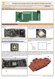
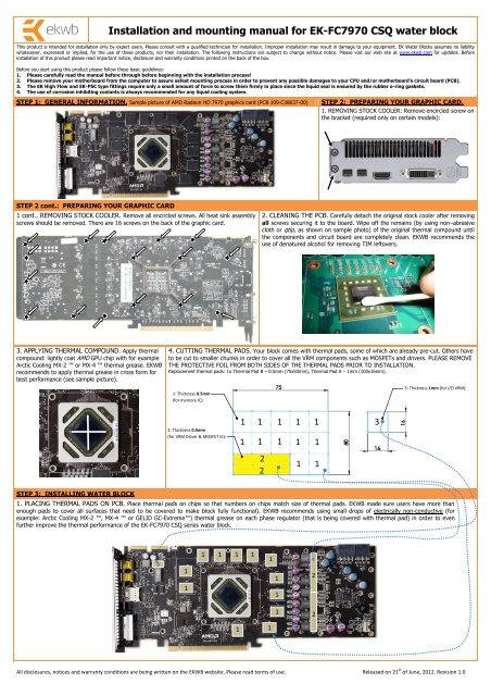
<strong>Installation</strong> <strong>and</strong> <strong>mounting</strong> <strong>manual</strong> <strong>for</strong> <strong>EK</strong>-<strong>FC7970</strong> <strong>CSQ</strong> water blockThis product is intended <strong>for</strong> installation only by expert users. Please consult with a qualified technician <strong>for</strong> installation. Improper installation may result in damage to your equipment. <strong>EK</strong> Water Blocks assumes no liabilitywhatsoever, expressed or implied, <strong>for</strong> the use of these products, nor their installation. The following instructions are subject to change without notice. Please visit our web site at www.ekwb.com <strong>for</strong> updates. Be<strong>for</strong>einstallation of this product please read important notice, disclosure <strong>and</strong> warranty conditions printed on the back of the box.Be<strong>for</strong>e you start using this product please follow these basic guidelines:1. Please carefully read the <strong>manual</strong> be<strong>for</strong>e through be<strong>for</strong>e beginning with the installation process!2. Please remove your motherboard from the computer to assure safest <strong>mounting</strong> process in order to prevent any possible damages to your CPU <strong>and</strong>/or motherboard’s circuit board (PCB).3. The <strong>EK</strong> High Flow <strong>and</strong> <strong>EK</strong>-PSC type fittings require only a small amount of <strong>for</strong>ce to screw them firmly in place since the liquid seal is ensured by the rubber o-ring gaskets.4. The use of corrosion inhibiting coolants is always recommended <strong>for</strong> any liquid cooling system.STEP 1: GENERAL INFORMATION. Sample picture of AMD Radeon HD 7970 graphics card (PCB 109-C38637-00)STEP 2: PREPARING YOUR GRAPHIC CARD.1. REMOVING STOCK COOLER: Remove encircled screw onthe bracket (required only on certain models):STEP 2 cont.: PREPARING YOUR GRAPHIC CARD1 cont.. REMOVING STOCK COOLER. Remove all encircled screws. All heat sink assemblyscrews should be removed. There are 16 screws on the back of the graphic card.2. CLEANING THE PCB. Carefully detach the original stock cooler after removingall screws securing it to the board. Wipe off the remains (by using non–abrasivecloth or qtip, as shown on sample photo) of the original thermal compound untilthe components <strong>and</strong> circuit board are completely clean. <strong>EK</strong>WB recommends theuse of denatured alcohol <strong>for</strong> removing TIM leftovers.3. APPLYING THERMAL COMPOUND. Apply thermalcompound: lightly coat AMD GPU chip with <strong>for</strong> exampleArctic Cooling MX-2 or MX-4 thermal grease. <strong>EK</strong>WBrecommends to apply thermal grease in cross <strong>for</strong>m <strong>for</strong>best per<strong>for</strong>mance (see sample picture).4. CUTTING THERMAL PADS. Your block comes with thermal pads, some of which are already pre-cut. Others haveto be cut to smaller chunks in order to cover all the VRM components such as MOSFETs <strong>and</strong> drivers. PLEASE REMOVETHE PROTECTIVE FOIL FROM BOTH SIDES OF THE THERMAL PADS PRIOR TO INSTALLATION.Replacement thermal pads: 1x Thermal Pad B – 0.5mm (75x50mm), Thermal Pad A – 1mm (100x16mm).1: Thickness 0.5mm(<strong>for</strong> memory IC):3: Thickness 1mm (<strong>for</strong> I/O VRM):2: Thickness 0.5mm(<strong>for</strong> VRM Driver & MOSFET IC):1 1 1 1 11 1 1 1 1221 13STEP 3: INSTALLING WATER BLOCK1. PLACING THERMAL PADS ON PCB. Place thermal pads on chips so that numbers on chips match size of thermal pads. <strong>EK</strong>WB made sure users have more thanenough pads to cover all surfaces that need to be covered to make block fully functional). <strong>EK</strong>WB recommends using small drops of electrically non-conductive (<strong>for</strong>example: Arctic Cooling MX-2 , MX-4 or GELID GC-Extreme) thermal grease on each phase regulator (that is being covered with thermal pad) in order to evenfurther improve the thermal per<strong>for</strong>mance of the <strong>EK</strong>-<strong>FC7970</strong> <strong>CSQ</strong> series water block.3111 1 1 111121211All disclosures, notices <strong>and</strong> warranty conditions are being written on the <strong>EK</strong>WB website. Please read terms of use. Released on 21 st of June, 2012. Revision 1.0
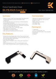
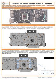
2. PLACING BLOCK TO GRAPHIC CARD. Carefully position the water block withpreinstalled 2.5mm st<strong>and</strong>offs on to the graphics card. During this process please makesure you align <strong>mounting</strong> holes on PCB with holes on the water block. Also pay attentionnot to use too much <strong>for</strong>ce by pressing block down to PCB. Chip dies are prone tocracking.3. ATTACHING BLOCK TO GRAPHIC CARD. By using Philips screwdriver screw inenclosed M3x4 DIN7985 screws. <strong>EK</strong>WB recommends start screwing the screws aroundthe GPU core <strong>and</strong> continue outwards. Always use a PVC washer under each <strong>and</strong> everyscrew!Use 11 screws M3x4Use 11 enclosed PVCwashers underneath eachscrew!STEP 4: CHECKING FOR CONTACTSTemporarily remove the water block to check <strong>for</strong> uni<strong>for</strong>m surface contact between the block <strong>and</strong> the components, pay special attention to the VRM section of the graphics card.Check whether the water block makes contact with the VRM. Then repeat sub-steps in previous section to re-attach the block. In case you fail to obtain good contact,please check again your thermal pad thickness or contact our support service.STEP 7: INSERTING CARD IN YOUR PC CASESTEP 5: FITTING POSITIONINGCarefully lift your graphics card with installed block <strong>and</strong> insert it in your PC’smotherboard PCI-express expansion slot. Please bear in mind that your graphics card isprobably heavier than when it was equipped with original heat sink fan assembly. Oneneeds to be very careful when h<strong>and</strong>ling the graphics card. Avoid all un-neededmanipulation of the VGA/water block assembly that might damage your card or waterblock during final installation.Screw in the fittings in the G1/4 threaded openings on plastic top of the water block.<strong>EK</strong>WB recommends using <strong>EK</strong>-PSC fittings with the <strong>EK</strong>-<strong>FC7970</strong> <strong>CSQ</strong> series water blocks.To ensure that the tubes are securely attached to the barb/fittings, please use hoseclamps or an appropriate substitute. You can use any opening as an inlet/outlet port.Tubing<strong>EK</strong>-PSC FittingWater block topINSTALLING <strong>EK</strong>-FC LINK:Alternatively you can install the enclosed <strong>EK</strong>-FC Link which allows installation of both<strong>EK</strong>-FC Bridge system as well as the use of G1/4 threaded fittings.Please remove the middle M4x8 DIN7984 screw, install the <strong>EK</strong>-FC Link together withOR 14x1.5mm gaskets <strong>and</strong> secure it with enclosed M4x25 DIN7985 screw. Useenclosed 2.5mm Allen (hex) key!Once installed you can install two (preferably angled) G1/4 threaded fittings or any <strong>EK</strong>-FC Bridge <strong>CSQ</strong> series interconnect (serial or parallel)M4x25 DIN7984REQUIRED TOOLS AND MOUNTING SCREWS:<strong>EK</strong>-FC Linkscissorsphilips screwdriverthermal greaseOR 14x1.5mmAll disclosures, notices <strong>and</strong> warranty conditions are being written on the <strong>EK</strong>WB website. Please read terms of use. Released on 21 st of June, 2012. Revision 1.0