STEP 1: GENERAL INFORMATION ON PRODUCT ... - EKWB
STEP 1: GENERAL INFORMATION ON PRODUCT ... - EKWB
STEP 1: GENERAL INFORMATION ON PRODUCT ... - EKWB

You also want an ePaper? Increase the reach of your titles
YUMPU automatically turns print PDFs into web optimized ePapers that Google loves.
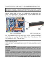
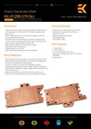
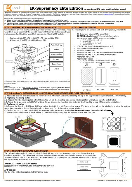
EK-Supremacy Elite Edition series universal CPU water block installation manualThis product is intended for installation only by expert users. Please consult with a qualified technician for installation. Improper installation may result in damage to your equipment. EK Water Blocks assumes no liabilitywhatsoever, expressed or implied, for the use of these products, nor their installation. The following instructions are subject to change without notice. Please visit our web site at www.ekwb.com for updates. Before installationof this product please read important notice, disclosure and warranty conditions printed on the back of the box.Before you start using this product please follow these basic guidelines:1. Please carefully read the manual before through before beginning with the installation process!2. Please remove your motherboard from the computer to assure safest mounting process in order to prevent any possible damages to your CPU and/or motherboard’s circuit board (PCB).3. The EK High Flow and EK-PSC type fittings require only a small amount of force to screw them firmly in place since the liquid seal is ensured by the rubber o-ring gaskets.4. The use of corrosion inhibiting coolants is always recommended for any liquid cooling system.<strong>STEP</strong> 1: <strong>GENERAL</strong> <strong>INFORMATI<strong>ON</strong></strong> <strong>ON</strong> <strong>PRODUCT</strong> COMPATIBILITYCongratulations on your purchase of EK-Supremacy universal CPU water block. Thiswater block is pre-assembled* for use with modern AMD or Intel desktop socket typemotherboards. By default this water block supports the following CPU sockets:- Intel socket LGA-775, LGA-1155/1156, LGA-1366 and LGA-2011- AMD socket S754/939/940, AMD AMx and FM1Water block topGasketsMounting plateJet plateCopper base<strong>STEP</strong> 2: TABLE OF C<strong>ON</strong>TENTThe following items are enclosed with each EK-Supremacy water block:- EK-Supremacy universal CPU water block- EK-TIM Indigo Extreme thermal interface material- PreciseMount universal CPU mounting mechanism:ooooM4 threaded thumb screws (4 pcs)Springs (4 pcs)M4 threaded thumb nuts (4 pcs)Washers (4 pcs)- LGA-2011 M4 threaded mounting studs (4 pcs)- Spare AMD / Intel mounting plate- Backplate rubber gasket- Backplate for Intel LGA-1366 and AMD socket motherboards- Backplate for Intel LGA-115x socket motherboards- Allen (hex) key 2.5mm- Additional jet plates:ooJet J2 (1.0mm thick) – optimized for LGA-1155/1156 CPUsJet J3 (0.7mm thick) – optimized for LGA-2011 CPUsScrews*: depending on the variant. EK-Supremacy Elite Edition – AMD AMx & FM1 is shipped factory pre-assembled withAMD mounting plate.Caution:Narrow server type LGA-2011 is not supported by default – a Mounting plate Supremacy LGA-2011 NarrowILM (EAN: 3830046990600) is mandatory to install this water block on narrow server type LGA-2011 motherboards.<strong>STEP</strong> 3.1 (optional): INSTALLING AMD MOUNTING PLATE AND REPLACING JET PLATE PROCEDURE1) Place water block on an even surface and remove the four M4x14 DIN7991 screws attaching the top to the copper base using the enclosed 2.5mm Allen key.2) Replacing mounting plate:2.1) Replace the Intel mounting plate with AMD one. You will feel the mounting plate locking into the position when placed correctly on to the top.2.2) Reseat the larger o-ring gasket (57x2 mm) into the gap between the mounting plate and water block top. Skip to step #4 to complete installation.3) Replacing jet plate:3.1) Remove the default jet J1 (0.8mm thick) and replace it with jet J2 or jet J3, depending on your CPU platform. You will feel the jet plate locking into the positionwhen placed correctly to the top. Reinstall smaller o-ring gasket if needed prior to replacing jet plate.4) Carefully place copper base to waterblock top assembly, make sure gaskets stay in place! Beware of copper base orientation!5) Repeat step #4 if necassery. Screw in all four (4) M4x14 DIN7991 screws using the enclosed 2.5mm Allen (hex) key.Step #2.2Step #3.1Step #4Step #2.1<strong>STEP</strong> 4: PREPARING BACKPLATE RUBBER GASKETThe enclosed rubber gasket is essential part of the backplate and mounting system and must be used every time youinstall this water block. The rubber backplate has a partially cut inner part which needs to be removed when installed onIntel LGA-115x and LGA-2011 motherboard. The rubber is held on four places and can be peeled away with hand. Thesetwo pieces can be reassembled later if needed.Intel LGA-115x and LGA-1366 socket:Remove the inner core of the rubber and use the outer part only.AMD sockets:Use the whole rubber backplate including the inner core.Outer partInner core(removable)All disclosures, notices and warranty conditions are being written on the back of the box. Revision 1.0. Released on 29 th of August, 2012.
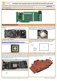
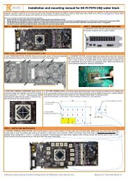
<strong>STEP</strong> 5: INSTALLING THE WATER BLOCK:<strong>STEP</strong> 5a: Intel LGA-775, -1366 and AMD socket motherboard:1) Place motherboard on an even surface with front facing down.2) Install backplate rubber gasket - depending on your CPU platform (see <strong>STEP</strong> 4) -and place metal backplate for Intel LGA-1366 and AMD socket to the back of yourmotherboard. Align the holes on the motherboard with holes on rubber gasketand backplate.3) Carefully rotate motherboard assembly with front side facing up with one handwhile holding the backplate and rubber in place with the other hand.4) Install the rest of mounting system as per installation manual (see <strong>STEP</strong> 6)<strong>STEP</strong> 5b: Intel LGA-115x socket motherboard:1) Place motherboard on an even surface with front facing down.2) Install backplate rubber gasket - depending on your CPU platform (see <strong>STEP</strong> 4) -and place metal backplate for Intel LGA-115x socket to the back of yourmotherboard. Align the holes on the motherboard with holes on rubber gasketand backplate. Make sure to orientate the rubber gasket to fit past theCPU socket ILM backplate.3) Carefully rotate motherboard assembly with front side facing up with onehand while holding the backplate and rubber in place with the other hand.4) Install the rest of mounting system as per installation manual (see <strong>STEP</strong> 6)Metal backplateRubber gasketMetal backplateRubber gasketMotherboardPCBMotherboardPCBfigure 1: Isometric view of backplate assembly for LGA-1366<strong>STEP</strong> 5c: Installing the mounting system:Intel Socket LGA-115x/1366 and AMD sockets:Install the M4 thumb screws of the PreciseMount mounting system onto yourmotherboard. It is mandatory to put 0.7mm plastic washer underneath each ofthe M4 thumb screws. Tighten the M4 thumb screw to the metal backplate withyour hands until you reach the end of the thread. Using tools (such as pliers) isnot recommended!Intel Socket LGA-2011:Install four (4) specific LGA-2011 M4 thumb screws into four M4 threaded stubson the LGA-2011 socket integrated latch mechanism (ILM). The screws are to beinstalled using no tools (i.e. pliers).LGA 2011 M4thumb screwM4 thumb screwPVC washerfigure 2: Isometric view of backplate assembly for LGA-115x<strong>STEP</strong> 5d: Preparing your CPU and applying EK-TIM Indigo Extreme:Please consult the enclosed EK-TIM Indigo Extreme installation manual andinstall the thermal interface material as per installation manual. Improperinstallation may will result in poor thermal properties of your EK-Supremacy EliteEdition series water block!Remember, EK-TIM Indigo Extreme is not re-usable once reflow process isstarted.<strong>STEP</strong> 5e: Fastening the waterblock:Install the waterblock on your CPU. Place an enclosed compression spring andthumb nut over each M4 thumb screw. Start fastening two thumb nuts at a time,preferably in cross pattern and do not tighten them fully until all of them arepartially screwed in. Then - using your fingers only - screw in all four thumb nutsuntil you reach the end of the thread.Thumb nutCoiled spring<strong>STEP</strong> 6: C<strong>ON</strong>NECTING WATER BLOCK TO THE COOLING CIRCUITCarefully identify the direction of the flow in your circuit. For the EK-Supremacyseries water block to operate properly the G1/4 port nearest to the center of thewater block MUST BE USED AS THE INLET PORT. EK recommends the use ofEK-PSC fittings. When using fittings other than EK-PSC series please use hoseclamps or appropriate substitute to secure the tubing to the barb. The use ofbiocide containing and corrosion inhibiting coolant is always recommended forany liquid cooling system.EK-PSC fittingTubingREQUIRED TOOLS- allen key 2.5mm (enclosed)All disclosures, notices and warranty conditions are being written on the back of the box. Revision 1.0. Released on 29 th of August, 2012.
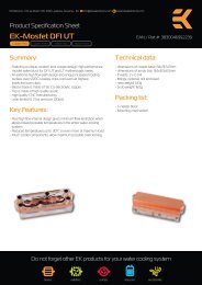
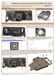
This product is intended for installation only by expert users. Improper installation may result in damage to your equipment. EK Water Blocks assumes no liability whatsoever, expressed or implied, for the use of these products, nor their installation. The followinginstructions are subject to change without notice. Please visit our web site at www.ekwaterblocks.com for updates. Before installation of this product please read important notice, disclosure, and warranty conditions printed on our home page.<strong>STEP</strong> 1: QUICK OVERVIEW<strong>STEP</strong> 1.1: EK-TIM Indigo Xtreme:Engineered Thermal Interface for Socket 2011 (IntelCore i7 processors)Indigo Xtreme is an Engineered Thermal Interface (ETI)that fits neatly between a CPU lid and heat sink orwaterblock to keep CPUs cooler. Unlike greases, metallicthermal interface pads or liquid metal alloys, IndigoXtreme is a self-contained and sealed structure, deployinga Phase Change Metallic Alloy (PCMA) which reflows andfills surface defects on the CPU lid and heat sink. Theresultant interfacial layer is void-free and robust, with lowthermal contact and bulk resistance.Important: Unlike most thermal interface products, the Indigo Xtreme form-factor isoptimized for each application.EK-TIM Indigo Extreme Installation Manualfor use with EK-Supremacy Series CPU Water Blocks<strong>STEP</strong> 1.2: Compatibility List:Supported Hardware:Supported CPUs: Socket 2011• Core i7Supported Water Blocks:All EK-Supremacy series water blocks• Plexi• Acetal• Full Copper• Full NickelAttempting to use Indigo Xtreme with CPUs or water blocks other than thosespecified may result in degraded performance or interfacial failure (See: SupportedHardware).<strong>STEP</strong> 1.3: ETI Kit Contents:The Indigo Xtreme ETI is offered as part of an Engineered Thermal Interface Kit. This kitincludes several cleanroom-grade surface cleaning products for (2) complete installations.The ETI kit includes:Indigo Xtreme ETIs (2 installations)Cleanroom-grade dry wiper clothsCotton cleaning swabsIndigo Xtreme Clean (sample size)Pair of powder-free nitrile glovesDetailed Installation GuideCheck the condition of the ETI kit before installation; if any problem is found,contact <strong>EKWB</strong> for a replacement.<strong>STEP</strong> 2.2: Thermal Interface Compound (grease) Removal:Using the supplied dry wiper cloth, apply pressure to thoroughly remove any existing interfacegrease from the CPU lid and water block. Clean with fresh areas of the wiper cloth until novisible grease residue is detected on the wiper.If removing metal pad or liquid metal TIM residue, refer to manufacturer’s specificcleaning methods.Prior to the installation and reflow of Indigo Xtreme do not disable the Thermal Controlfeature that protects your CPU from overheating.<strong>STEP</strong> 2: INSTALLATI<strong>ON</strong> PROCEDURERead entire instructions before using EK-TIM Indigo Xtreme. Computer operatingsystem and temperature monitoring utilities must be installed prior to use.Contact <strong>EKWB</strong> Support if you have any questions.Prior to installing EK-TIM Indigo Xtreme, complete the water block assembly(thru Step 5C) as illustrated in the EK-Supremacy installation manual.<strong>STEP</strong> 2.1: Motherboard, CPU and Block Removal:Remove the motherboard from the PC case. Remove the CPU from the motherboard socket and place ona non-abrasive, lint-free surface for cleaning. Motherboard removal will facilitate proper alignment of theETI to the CPU lid and water block.<strong>STEP</strong> 2.3: Put on Gloves:Prior to the final degreasing step, the supplied powder-free nitrile gloves must be worn to prevent anyfinger oils or contaminants from contacting the CPU lid, water block and ETI surfaces and to prevent skincontact with Indigo Xtreme Clean.Stray grease compound can be mitigated as gloves are applied immediately following theThermal Interface Compound Removal step.All disclosures, notices and warranty conditions are being written on <strong>EKWB</strong> web page. Please check terms of use. Revision 1.1. Released on 25 th of July, 2012.
<strong>STEP</strong> 2.4: Degrease CPU lid and Water Block Surfaces:Saturate a dry wiper cloth with Indigo Xtreme Clean; use ~1/2 trial size bottle per ETIinstallation; thoroughly wipe the CPU lid; repeat with the water block interfacial surfaces.Continue to wipe each surface with fresh areas of the wiper until no visible residue is detectedon the wiper. Wipe all surfaces of any visible lint, fibers, or particulates.Be prepared to wipe the CPU lid and water block surfaces immediately uponsaturating each dry wiper cloth as the Xtreme Clean solvent will quickly evaporate.New CPUs or water blocks must be degreased as well. Use only the supplied IndigoXtreme Clean for the degreasing step.Use the Xtreme Clean solvent in a well-ventilated area. Avoid contact with plastics(such as keyboards, computer cases, cooling fans, acetal and plexi water blockhousings, coolant tube fittings, cables, etc.). Also, avoid contact with elastomers(coolant tubing, gaskets, etc.).<strong>STEP</strong> 2.7: Bottom Side Liner Removal:Remove the “Bottom” side rectangular clear liner by slowlypeeling the liner, beginning from the corner with the whiteBOTTOM” label. Hold the ETI on the blue edges (with bothhands to prevent any wrinkling or warping) Do not remove the“Top” liner at this step.Do not touch the exposed adhesivearea after removal of the clear liner.Once the liner has been removed,proceed immediately to Step 2.8:Alignment and Placement.<strong>STEP</strong> 2.9: Top Side Liner Removal:Remove the “Top” side rectangular clear liner by slowly peelingthe liner, beginning from the corner with the white “TOP” label.Do not touch any of the clear surfaces afterremoval of the clear liner. Once the liner hasbeen removed, proceed immediately to Step2.10: Water Block Mounting.<strong>STEP</strong> 2.10: Water Block Mounting:Use the following mounting instructions to ensure optimal clamping force on the ETI:1. While holding the water block in a level/horizontal position, place the springsonto each thumb screw.2. Place thumb nuts on each screw and turn just enough to engage the threads.3. Temporarily mark each thumb nut with a marking pen or tape to indicate thestarting position (see the black markings illustrated on the top of each thumbnut in the image).4. Turn all thumb nuts five (5) full revolutions, beginning with the upper left andright thumb nuts (as illustrated in the image).5. Proceed to Step 3: ETI Reflow Procedure.<strong>STEP</strong> 2.5: CPU Installation:Install the CPU in the motherboard. Refer to motherboard or CPU installation instructions.The ETI can only be applied after correct installation of the CPU.<strong>STEP</strong> 2.6: Indigo Xtreme Handling:The Indigo Xtreme ETI may be handled on the blue surfaces only.ETI installation requires a lint-free environment.Do not remove the clear Top and Bottom liners prior to the specific installation step. Do notbend, flex or puncture any portion of the ETI. Keep all chemical agents (Indigo XtremeClean, etc.) away from the ETI.<strong>STEP</strong> 2.8: Alignment and Placement:Orientation and alignment of the ETI to the CPU lidand socket is critical. Orient the ETI such that theBottom side is facing the CPU lid. Refer to the figuresfor correct placement.Hold the ETI on the blue edges. Ensure that the ETI isoriented with CPU lid/socket as shown. Align the squareblue ring (indicated by the large red arrows) to the edgeof the CPU lid before making contact. Carefully lower theETI onto the CPU lid surface. With moderate, downwardfinger pressure, completely press down all ETI surfacesonto the CPU lid by following the square blue alignmentring. Additionally, press down the surface surroundingthe vent lid onto the CPU and the adhesive area to thesocket frame (see small red arrows).It is critical that the square blue alignment ring is completely on the CPU lid andall blue ring surfaces are thoroughly pressed down.It is imperative that the water block is aligned correctly beforeit makes contact with the ETI. Avoid any twisting on the ETIas the water block is bolted down.Be certain thumb nuts have been tightened only (5) fullrevolutions (from initial thread engagement); DO NOT fullytighten thumb nuts; excessive clamping force may damageETI, resulting in alloy leakage and/or poor thermalperformance.All disclosures, notices and warranty conditions are being written on <strong>EKWB</strong> web page. Please check terms of use. Revision 1.1. Released on 25 th of July, 2012.
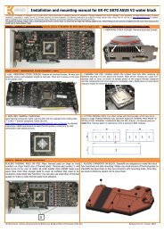
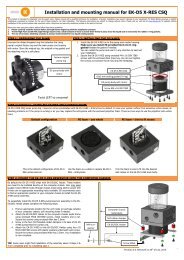
<strong>STEP</strong> 3: ETI REFLOW PROCEDURE:ETI Reflow:As part of installation, the Indigo Xtreme ETI must first be heated with the CPU running under load in order to reflow (melt) the PCMA.The interface is highly thermally resistive without a complete reflow. Failure to perform the exact reflow procedure may result in unacceptable thermal performance. A videodemonstration of ETI reflow can be found at <strong>EKWB</strong> product page: http://www.ekwb.com1. Connect up all liquid lines to the water block.2. Orient the computer such that the motherboard and CPU are in a horizontal position.3. Turn on the liquid pump.4. Boot the computer. Clock frequency and voltage must be set to default (stock).5. Use a CPU temperature monitoring program (such as SpeedFan) and select the graphing option to track the profile of all core temperatures during reflow. Be certain the graph is openwith all core temperatures selected before proceeding to the next step.6. With the computer running, turn off the liquid pump.7. Exercise the CPU with a “burn” program (such as Prime 95) to generate adequate heat for reflow. Multi-core CPUs require one open copy of the burn program for each core.8. Follow the average core temperature profile (with SpeedFan) illustrated in the graph and corresponding tables below for your particular water block.Full copper/nickel water blocks will require longer reflow times.Average Core Temperature (°C)Average Core Temperature (°C)Plexi/Acetal Water Blocks100#2#690 #380#570#460#750#1400 15 30 45 60 75 90 115 130100908070605040Time (seconds)Full Copper/Nickel Water Blocks#2 #3#6#5#4#7#10 1 2 3 4 5 6Time (minutes)# Plexi/Acetal Water Blocks Full Copper/Nickel Water Blocks1234567All burn programs have been activated andliquid pump has been turned off.Core temperatures will immediately rise topeak of ~90-95°C.Core temperatures will quickly descend withinseconds of activating burn programs.All core temperatures will drop to a BottomingPoint (lowest temperature).Following the Bottoming Point, average coretemperatures will slowly rise again.Once the average core temperature hasreached ~85-90°C, de-activate all burnprograms.All core temperatures will again drop to thesecond Bottoming Point. Once the lowesttemperature is reached, turn on liquid pump.All burn programs have been activated andliquid pump has been turned off.Core temperatures will immediately rise to peakof ~90-95°C.Core temperatures will somewhat stabilize for afew minutes and then slowly descend.All core temperatures will drop to a BottomingPoint (lowest temperature).Following the Bottoming Point, average coretemperatures will slowly rise again.Once the average core temperature hasreached ~85-90°C, de-activate all burnprograms.All core temperatures will again drop to thesecond Bottoming Point. Once the lowesttemperature is reached, turn on liquid pump.Intel multi-core processors have built-in protection (Adaptive Thermal Monitor) thatprevents the processor from exceeding maximum core temperatures, therebypreventing any damage to the CPU.Avoid any bumping or excessive pressure on the heat sink/waterblock and keep thecomputer in the horizontal position until the average core temperature has droppedbelow 60°C.If the average core temperature does not follow a similar temperature profile as seenin the previous graphics, then improper reflow may have occurred. Proceed to“Removal” and re-install a new ETI.All disclosures, notices and warranty conditions are being written on <strong>EKWB</strong> web page. Please check terms of use. Revision 1.1. Released on 25 th of July, 2012.
REMOVAL OF EK-TIM INDIGO XTREME:To disassemble, loosen the water block thumb nuts. The ETI may then be removed (intact) by first slowly peeling each corner. The ETI is designed to adhesively capture excess alloy (from differences ofCPU lid/heat sink interfacial roughness and planarity) on their surfaces. Any residual adhesive on the CPU or water block may be removed with the edge of a credit card and with Xtreme Clean, acetone, orxylene on a clean wiper or cotton cleaning swab. Residual alloy is best removed by wetting the supplied swab with Xtreme Clean and gentling rotating the swab to loosen and collect the alloy particles.Indigo Xtreme is a single-use interface product and any removal of the water block (pre/post-reflow) will require a new ETI. All interface material and adhesive residue must be removed andthe CPU and water block re-cleaned (with the surface cleaning supplies including in the ETI kit only) prior to the re-installation of a new ETI.REFERENCES:Burn in program: IntelBurnTest: http://www.softpedia.com/get/System/Benchmarks/IntelBurnTest.shtmlTemperature monitors: Motherboard manufacturers usually supply a hardware monitor utility for their boards. CPUID.org's HWMonitor (Pro) or SpeedFan are the most popular temperature monitoringtool. It includes a real-time graphing mode that will aid in the monitoring of the processor burn-in: http://www.almico.com/speedfan.php ; http://www.cpuid.com/softwares/hwmonitor.htmlThe Material Safety Data Sheet (MSDS) for Indigo Xtreme Clean can be found at: http://www.ekwaterblocks.com/shop/EK-TIM/MSDS_Indigo.pdfContact us for more information about this or other EK-TIM Indigo Xtreme applications at our website: http://www.ekwb.comStore EK-TIM Indigo Xtreme at room temperature conditions of 22°C (72°F) and 50% R.H., preferably in the original sealed enclosure and plastic bag.DISCLAIMER:<strong>EKWB</strong> d.o.o. and Enerdyne Solutions are not responsible for any damages due to external causes, including but not limited to, improper use, accident, neglect,alteration, repair, improper installation, improper testing, or damages caused by overclocking.Intel, Core i7 are trademarks of the Intel Corporation, USA.EK-Supremacy is a trademark of <strong>EKWB</strong> d.o.oIndigo Xtreme is a trademark of:Enerdyne Solutions, Inc.,125 West North Bend Way, PO Box 2660,North Bend, WA., 98045 United States of AmericaAll disclosures, notices and warranty conditions are being written on <strong>EKWB</strong> web page. Please check terms of use. Revision 1.1. Released on 25 th of July, 2012.