Installation and mounting manual for EK-FC 5870 ASUS V2 ... - EKWB
Installation and mounting manual for EK-FC 5870 ASUS V2 ... - EKWB
Installation and mounting manual for EK-FC 5870 ASUS V2 ... - EKWB

You also want an ePaper? Increase the reach of your titles
YUMPU automatically turns print PDFs into web optimized ePapers that Google loves.
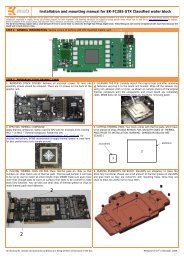
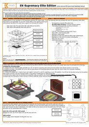
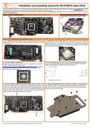
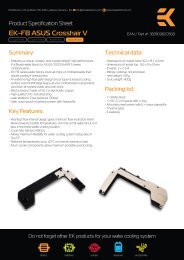
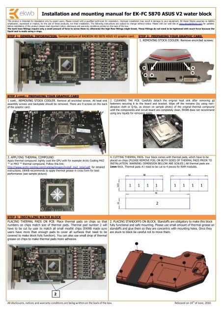
<strong>Installation</strong> <strong>and</strong> <strong>mounting</strong> <strong>manual</strong> <strong>for</strong> <strong>EK</strong>-<strong>FC</strong> <strong>5870</strong> <strong>ASUS</strong> <strong>V2</strong> water blockThis product is intended <strong>for</strong> installation only by expert users. Please consult with a qualified technician <strong>for</strong> installation. Improper installation may result in damage to your equipment. <strong>EK</strong> Water Blocks assumes no liabilitywhatsoever, expressed or implied, <strong>for</strong> the use of these products, nor their installation. The following instructions are subject to change without notice. Please visit our web site at www.ekwaterblocks.com <strong>for</strong> updates.Be<strong>for</strong>e installation of this product please read important notice, disclosure <strong>and</strong> warranty conditions printed on the back of the box.The barb hose fittings require only a small amount of <strong>for</strong>ce to screw them in; otherwise the high flow fittings might break. These fittings do not need to be tightened with much <strong>for</strong>ce because theliquid seal is made using o-rings.STEP 1: GENERAL INFORMATION. Sample picture of RADEON HD <strong>5870</strong> <strong>ASUS</strong> <strong>V2</strong> graphic card.STEP 2: PREPARING YOUR GRAPHIC CARD.1. REMOVING STOCK COOLER: Remove encircled screws:STEP 2 cont.: PREPARING YOUR GRAPHIC CARD1 cont.. REMOVING STOCK COOLER. Remove all encircled screws. All heat sinkassembly screws <strong>and</strong> backplate should be removed. There are 9 screws on the backof the graphic card.2. CLEANING THE PCB. Carefully detach the original heat sink after removing allfasteners securing it to the board <strong>and</strong> bracket. Wipe off the remains (by using non–abrasive cloth or Q-tip, as shown on sample photo) of the original thermal compounduntil the components <strong>and</strong> circuit board are completely clean. <strong>EK</strong>WB does not recommendusing any liquids <strong>for</strong> removing paste.3. APPLYING THERMAL COMPOUNDApply thermal compound: lightly coat the GPU with <strong>for</strong> example Arctic Cooling MX2 or MX3 thermal compound. Follow this link:http://www.arctic-cooling.com/catalog/images/install_mx2_retail.pdf <strong>for</strong> detailedinstructions. <strong>EK</strong>WB recommends to apply thermal grease in cross <strong>for</strong>m <strong>for</strong> bestper<strong>for</strong>mance (see sample picture).4. CUTTING THERMAL PADS. Your block comes with thermal pads, which have to beplaced on chips (PLEASE REMOVE FOIL ON BOTH SIDES OF THERMAL PADS PRIOR TOINSTALLATION. WARNING: DIMENSION BELLOW ARE SCALED.) All thermal pads are1mm thick. Thermal pads #1 need to be cut to 4 pieces <strong>for</strong> RAM modules.1 1 1 11 1 1 12STEP 3: INSTALLING WATER BLOCKPLACING THERMAL PADS ON PCB. Place thermal pads on chips so thatnumbers on chips match size of thermal pads. Thermal pad number 2 willhave to be cut by user to match all small mosfet chips (<strong>EK</strong>WB made sureusers have more than enough pads to cover all surfaces that need to becovered to make block fully function). You can also use small drop of thermalgrease on chips to make thermal pads more adhesive.2. PLACING STANDOFFS ON BLOCK. St<strong>and</strong>offs are obligatory to make this blockfully functional <strong>and</strong> safe <strong>mounting</strong>. Please use small amount of thermal grease onst<strong>and</strong>offs <strong>and</strong> glue them so they are concentric with <strong>mounting</strong> holes. Once theyare stuck to block be careful not to move them.1 1 1 111112All disclosures, notices <strong>and</strong> warranty conditions are being written on the back of the box. Released on 14 th of June, 2010.
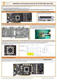
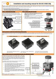
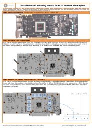
3. PLACING BLOCK TO GRAPHIC CARD. During this process please make sure youalign holes on PCB with holes on block. Also pay attention not to use too much <strong>for</strong>ceby pressing block down to PCB. Chips are prone to cracking.4. ATTACHING BLOCK TO GRAPHIC CARD. By using Philips screwdriver screw in enclosedM3x6 screws. <strong>EK</strong>WB recommends start screwing the screws around the GPU core <strong>and</strong>continue outwards.Use 7 screws M3x6STEP 4: CHECKING FOR CONTACTSTemporarily remove the water block to check <strong>for</strong> uni<strong>for</strong>m surface contact between the block <strong>and</strong> the components. Note the pattern of contact on a piece of paper. Then repeatsubsteps in previous section to reattach the block. In case you can’t get good contact, please check again your thermal pad thickness our contact our support service.STEP 5: POSITIONING FITTINGSPlease use spacer only on copper base if you use fitting with G1/4 thread longer than 5mm (see sample picture). Screw in the fittings <strong>and</strong> plugs (please use spacers only oncopper base <strong>for</strong> fittings). Use 6mm Allen key to screw in <strong>and</strong> tighten new <strong>EK</strong>-Plug G1/4. Attach the liquid cooling tubes <strong>and</strong> connect the water-block(s) into the cooling circuit.<strong>EK</strong>WB recommends using high flow fittings with the <strong>EK</strong>-<strong>FC</strong> <strong>5870</strong> <strong>V2</strong> series water blocks. To ensure that the tubes are securely attached to the barb/fittings, please use hoseclamps or an appropriate substitute. The use of an algaecide is always recommended <strong>for</strong> any liquid cooling system.You can use any hole as an inlet/outlet hole.FittingG1/4Spacer6mm Allen keyGasket/O-ringPlugPlugSTEP 6: INSERTING CARD IN YOUR PC CASECarefully lift your card with installed block <strong>and</strong> insert it in your PC case. Please bear in mind that your card suddenly withst<strong>and</strong>s extra weight thus again be very careful not tobend it or cause any other unneeded moves that might damage your card or block during installation.REQUIRED TOOLS AND MOUNTING SCREWS:scissors philips screwdriver 7 x screws M3x6 DIN7985All disclosures, notices <strong>and</strong> warranty conditions are being written on the back of the box. Released on 14 th of June, 2010.