secondary electron emission of ceramics used in the channel of spt
secondary electron emission of ceramics used in the channel of spt
secondary electron emission of ceramics used in the channel of spt

Create successful ePaper yourself
Turn your PDF publications into a flip-book with our unique Google optimized e-Paper software.
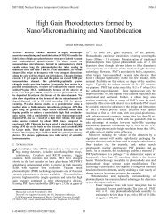
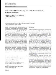
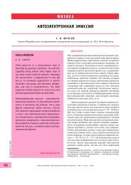
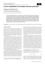
<strong>electron</strong> gunEcollect<strong>in</strong>g electrodeIisamplesample-holderIdIsfigure 1 : Schematic view <strong>of</strong> <strong>the</strong> experimental set-up.The <strong>secondary</strong> <strong>emission</strong> yield σ is <strong>the</strong>n calculated by <strong>the</strong> relation :IS(E)σ (E) =I (E) I (E)S+Rwhere :I S is <strong>the</strong> <strong>secondary</strong> <strong>electron</strong>s currentI R is <strong>the</strong> replacement currentIi is <strong>the</strong> total current <strong>of</strong> <strong>the</strong> <strong>in</strong>cident <strong>electron</strong>s. Ii = I S + I RE is <strong>the</strong> energy <strong>of</strong> <strong>in</strong>cident <strong>electron</strong>sS<strong>in</strong>ce <strong>the</strong> measurements were performed on very <strong>in</strong>sulat<strong>in</strong>g samples, <strong>the</strong> measurement is based on a pulsedtechnique. The <strong>in</strong>cident current has <strong>the</strong> shape <strong>of</strong> a squared signal whose duration is few tens <strong>of</strong> µs andamplitude few tens <strong>of</strong> nA, each pulse is triggered manually. The currents I S and I R are amplified andmeasured with an oscilloscope.2.2 Particularity <strong>of</strong> measurements <strong>of</strong> SEE on <strong>in</strong>sulatorsThe peculiarity <strong>of</strong> <strong>the</strong> materials tested <strong>in</strong> this study is <strong>the</strong>ir <strong>in</strong>sulat<strong>in</strong>g nature. Their behaviour under an<strong>electron</strong> beam depends on <strong>the</strong> <strong>emission</strong> yield σ. Two cases can be separated :σ > 1 : After each pulse <strong>of</strong> current, <strong>the</strong> material becomes charged positively and <strong>the</strong> <strong>secondary</strong> <strong>electron</strong>shav<strong>in</strong>g a low energy are attracted and back-collected by <strong>the</strong> sample surface. This phenomenon follows onuntil <strong>the</strong> quantity <strong>of</strong> <strong>electron</strong>s emitted from <strong>the</strong> surface are equal to those <strong>in</strong>cident. In this case, <strong>the</strong> apparent<strong>emission</strong> yield is equal to 1 and <strong>the</strong> surface potential is positive.σ < 1 : After each pulse <strong>of</strong> <strong>in</strong>cident current, <strong>the</strong> surface potential becomes negative by <strong>electron</strong>saccumulation on <strong>the</strong> surface. Most <strong>of</strong> <strong>the</strong> <strong>in</strong>cident <strong>electron</strong>s are reflected by <strong>the</strong> surface and <strong>the</strong> apparentyield is 1.An example <strong>of</strong> <strong>the</strong> <strong>in</strong>fluence <strong>of</strong> surface potential is visible on figure 2. In this case, <strong>the</strong> material tested is AlNand <strong>the</strong> <strong>in</strong>cident current <strong>of</strong> <strong>electron</strong>s is 140 nA with an energy <strong>of</strong> 100 eV. You can observe that <strong>the</strong> currentcollected by <strong>the</strong> electrode decreases after each pulse and reaches <strong>the</strong> value <strong>of</strong> <strong>in</strong>cident current after 20measurements. Dur<strong>in</strong>g this time, <strong>the</strong> current on <strong>the</strong> sample follows <strong>the</strong> same curve and decreases to 0. At <strong>the</strong>energy <strong>of</strong> 100 eV for <strong>in</strong>cident <strong>electron</strong>s, <strong>the</strong> SEE yield <strong>of</strong> AlN is about 2, but after few measurements, thismeasured SEE yield decreases to reach <strong>the</strong> value <strong>of</strong> 1.2
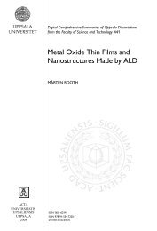
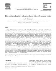
Is Ir σcurrent (nA)300250200150100502.01.81.61.41.21.00.80.60.40.2SEE yield00.00 5 10 15 20number <strong>of</strong> mesaurementsfigure 2 : Currents measured on collect<strong>in</strong>g electrode and replacement current on <strong>the</strong> sample(left vertical axis) and SEE apparent yield (right axis) versus <strong>the</strong> number <strong>of</strong> measurements.This result shows that <strong>the</strong> measurement <strong>of</strong> <strong>secondary</strong> <strong>electron</strong>s <strong>emission</strong> yield has to follows twocontradictory rules :• send<strong>in</strong>g <strong>electron</strong>s on <strong>the</strong> surface to generate <strong>secondary</strong> <strong>electron</strong>s• not charg<strong>in</strong>g <strong>the</strong> surfaceThis was only solved <strong>in</strong> this experience reduc<strong>in</strong>g <strong>the</strong> pulse duration and amplitude but o<strong>the</strong>rs systems couldbe <strong>used</strong> such as neutralisation <strong>of</strong> <strong>the</strong> sample surface by UV or ion beam.2.3 Energy <strong>of</strong> emitted <strong>electron</strong>sIn order to understand better <strong>the</strong> <strong>in</strong>fluence <strong>of</strong> potential surface and phenomenon <strong>of</strong> “apparent” yield, <strong>the</strong>experiment has been modified to study <strong>the</strong> energy <strong>of</strong> emitted <strong>electron</strong>s. The cyl<strong>in</strong>drical collector has beenremoved and replaced by an hemispherical one equipped <strong>in</strong>ternally with a grid whose potential can bemodified. The experimental conditions are those described previously, <strong>the</strong> collect<strong>in</strong>g electrode is fixed to apotential <strong>of</strong> +9Volts. The pulse <strong>of</strong> primary <strong>electron</strong>s is about 100 nA dur<strong>in</strong>g 4 µs. This set-up allows <strong>the</strong>experimenter to select all <strong>the</strong> <strong>electron</strong>s whose energy is more than <strong>the</strong> voltage applied on <strong>the</strong> grid. As <strong>the</strong>pulses are not perfectly reproducible, <strong>the</strong> experimental results presented here are normalised, i.e. <strong>the</strong>measured current is divided by <strong>the</strong> <strong>in</strong>cident current.Two examples <strong>of</strong> results are presented on figure 3 for AlN and on figure 4 for AlNBN. Dur<strong>in</strong>g <strong>the</strong>seexperiments, <strong>the</strong> energy <strong>of</strong> <strong>in</strong>cident <strong>electron</strong>s takes 3 values 40 eV, 60 eV and 80 eV. The grid potential isswept from 0 to – 40V but <strong>the</strong> graphs present this potential <strong>in</strong> absolute value to correlate it directly with<strong>electron</strong>s energy.3
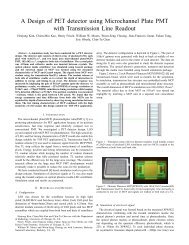
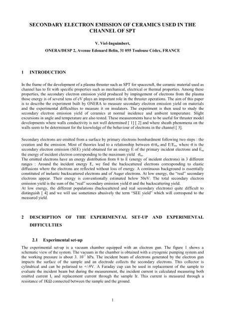
40eV 60 eV 80 eV40eV 60 eV 80 eVnormalised collected current1.210.80.60.40.200 10 20 30 40grid potential (V)normalised collected current0.70.60.50.40.30.20.100 10 20 30 40grid potential (V)figure 3 : Electron energy distribution <strong>of</strong><strong>secondary</strong> <strong>electron</strong>s for AlNfigure 4 : Electron energy distribution <strong>of</strong><strong>secondary</strong> <strong>electron</strong>s for AlN-BNIn <strong>the</strong> case <strong>of</strong> AlN (figure 3), <strong>the</strong> shapes <strong>of</strong> <strong>the</strong> different curves are <strong>the</strong> same and <strong>in</strong> a good agreement withthose observed <strong>in</strong> bibliography [ 4]. For this material, all <strong>the</strong> <strong>electron</strong>s emitted are real <strong>secondary</strong> <strong>electron</strong>swith a low energy and not dependant with <strong>the</strong> <strong>in</strong>cident <strong>electron</strong>s energy. This is possible because <strong>the</strong> surfaceis positively charged which is <strong>the</strong> case when <strong>the</strong> SEE yield σ > 1 and will be confirmed by <strong>the</strong> results given<strong>in</strong> <strong>the</strong> next paragraph.In <strong>the</strong> case <strong>of</strong> AlN-BN (figure 4), <strong>the</strong> phenomenon is totally different : it seems that all <strong>the</strong> emitted <strong>electron</strong>sare <strong>electron</strong>s reflected by <strong>the</strong> surface potential which can reach <strong>the</strong> potential <strong>of</strong> primary <strong>electron</strong>s. Forexample, for <strong>the</strong> energy <strong>of</strong> 40 eV, most <strong>of</strong> <strong>the</strong> collected <strong>electron</strong>s have an energy above 30 eV and <strong>the</strong>current becomes null for V grid =35 V. This phenomenon is characteristic <strong>of</strong> a negative polarised surfacewhich reflects totally <strong>the</strong> <strong>in</strong>cident <strong>electron</strong>s, this is <strong>the</strong> signature <strong>of</strong> a SEE yield σ < 1 and will be confirmedby <strong>the</strong> results given <strong>in</strong> <strong>the</strong> next paragraph.3 RESULTS ON SEVERAL CERAMICSDifferent <strong>ceramics</strong> were measured dur<strong>in</strong>g this study and <strong>the</strong> results are presented hereafter. They are : BN-SiO 2 , BN-AlN, AlN, MgO, SiC, Al 2 O 3 and BN.For all <strong>the</strong>se experiments, <strong>the</strong> configuration adopted is <strong>the</strong> one presented <strong>in</strong> <strong>the</strong> paragraph 3.1 with <strong>the</strong>sample not polarised and <strong>the</strong> cyl<strong>in</strong>drical collector polarised to +9V.3.1 BNSiO 2 , BN, AlNBN, SiC :These samples are bulk material <strong>of</strong> few mm <strong>of</strong> thickness. Their rear face are metallized with alum<strong>in</strong>ium torealise an electric contact with <strong>the</strong> sample holder. The result <strong>of</strong> <strong>secondary</strong> <strong>electron</strong> <strong>emission</strong> <strong>of</strong> <strong>the</strong>se 4materials is shown on figure 5.4
SEE yield2.521.510.5AlNBNSiCBNSiO2BN00 20 40 60 80 100energy <strong>of</strong> primary <strong>electron</strong>s (eV)figure 5 : SEE yield <strong>of</strong> BNSiO 2, BN, AlNBN and SiC with respect to <strong>the</strong> primary <strong>electron</strong>senergyFor <strong>the</strong>se materials, <strong>the</strong> <strong>secondary</strong> <strong>electron</strong> <strong>emission</strong> yield becomes below than 1 for an energy <strong>of</strong> <strong>the</strong>primary <strong>electron</strong>s above a threshold which varies from 30 eV for BN to 70 eV for AlNBN. S<strong>in</strong>ce <strong>the</strong>maximum <strong>of</strong> SEE seems to be almost reached at 100 eV for BNSiO2, AlNBN and SiC, SEE <strong>of</strong> Boron Nitrate(BN) still <strong>in</strong>creases and atta<strong>in</strong>s 2 at 100 eV.The <strong>in</strong>certitude <strong>of</strong> <strong>the</strong>se measurements was not added on this graph to simplify but is about +/- 20%.3.2 MgO, Al 2 O 3 , AlNThe samples are bulk materials <strong>of</strong> few mm <strong>of</strong> thickness. Their rear face are metallized with alum<strong>in</strong>ium. Theresult <strong>of</strong> <strong>secondary</strong> <strong>electron</strong> <strong>emission</strong> <strong>of</strong> <strong>the</strong>se 3 materials is shown on figure 6. For <strong>the</strong>se materials, a SEEyield below than 1 was not measured even at low <strong>in</strong>cident energy but <strong>the</strong> yield reached by Al 2 O 3 is quitelarger than <strong>the</strong> o<strong>the</strong>rs s<strong>in</strong>ce this value is 3 at 100 eV.SEE yield32.521.510.50Al2O3 MgO AlN0 20 40 60 80 100energy <strong>of</strong> primary <strong>electron</strong>s (eV)figure 6 : SEE yield <strong>of</strong> MgO, Al 2O 3and AlN with respect to <strong>the</strong> primary <strong>electron</strong>s energy4 EXCURSIONS IN ANGLE AND TEMPERATURE4.1 Influence <strong>of</strong> <strong>the</strong> temperature on SEE yield.Know<strong>in</strong>g that <strong>channel</strong>’s walls <strong>in</strong> <strong>the</strong> SPT are at a very high temperature [ 5], it seemed <strong>in</strong>terest<strong>in</strong>g to know<strong>the</strong> <strong>in</strong>fluence <strong>of</strong> this temperature on <strong>secondary</strong> <strong>electron</strong> <strong>emission</strong>. We could imag<strong>in</strong>e that <strong>the</strong> SEE yield will<strong>in</strong>crease with temperature s<strong>in</strong>ce <strong>the</strong> energy transfer <strong>of</strong> <strong>in</strong>cident <strong>electron</strong> with <strong>the</strong> material’s matrix willdecrease. Never<strong>the</strong>less, Dekker [ 6] th<strong>in</strong>ks that this effect will be masked by dependence with temperature <strong>of</strong>5
mean free path which decreases while temperature <strong>in</strong>crease. This is confirmed by measurements performedby Johnson and McKay on MgO [ 7]. These results show a decrease <strong>of</strong> SEE yield at high temperature andhigh <strong>in</strong>cident <strong>electron</strong> energy on MgO. However, no real evidence <strong>of</strong> modification <strong>of</strong> this yield is given <strong>in</strong><strong>the</strong> range which is under <strong>in</strong>terest <strong>in</strong> this study (i. e. low energy under 100eV).In order to obta<strong>in</strong> experimental results on this subject, <strong>the</strong> experimental set-up was slightly modified <strong>in</strong> orderto <strong>in</strong>crease <strong>the</strong> samples temperature. However, <strong>the</strong> maximum possible temperature without modify<strong>in</strong>gcompletely <strong>the</strong> set-up, was only 300°C. The sample was heated with a hot element put <strong>in</strong> contact with <strong>the</strong>sample holder dur<strong>in</strong>g <strong>the</strong> time necessary to reach 300°C. The contact was <strong>the</strong>n suppress <strong>in</strong> order to proceedwith <strong>the</strong> measurement. Sample’s temperature was measured with a <strong>the</strong>rmocouple. No real effect wasmeasured on <strong>the</strong> different samples and 2 examples <strong>of</strong> result are presented on figure 7 and figure 8.σ2.521.510.5Tamb before 300°C Tamb after2.521.5σ10.5Tamb before 300°C Tamb after00 20 40 60 80 100Energy (eV)00 20 40 60 80 100Energy (eV)figure 7 : SEE yield measured on BNSiO 2atambient temperature before and after heat<strong>in</strong>gand SEE yield at 300°C.figure 8 : SEE yield measured on MgO atambient temperature before and after heat<strong>in</strong>gand SEE yield at 300°C.We observed on <strong>the</strong>se results that <strong>the</strong> SEE yield at 300 °C <strong>in</strong>creases <strong>of</strong> about 15% and that <strong>the</strong>re is also avariation <strong>of</strong> <strong>the</strong> yield at ambient temperature after <strong>the</strong> heat<strong>in</strong>g. S<strong>in</strong>ce <strong>the</strong> dispersion <strong>of</strong> <strong>the</strong> measurements isabout 20%, <strong>the</strong> variation observed <strong>in</strong> SEE at 300°C is negligible. Concern<strong>in</strong>g <strong>the</strong> measurement at ambienttemperature after heat<strong>in</strong>g, this evolution is very slight and could be eventually attributed to a modification <strong>of</strong>surface’s sample like simple clean<strong>in</strong>g while heat<strong>in</strong>g.4.2 Influence <strong>of</strong> <strong>in</strong>cidence angle on SEE yieldThis aspect was more studied <strong>in</strong> bibliography than <strong>the</strong> <strong>in</strong>fluence <strong>of</strong> temperature. Shih [ 4] had tested <strong>the</strong><strong>in</strong>fluence <strong>of</strong> <strong>the</strong> angle <strong>of</strong> <strong>in</strong>cidence <strong>of</strong> primary <strong>electron</strong>s on SEE yield on Molybdenum and <strong>the</strong> result is an<strong>in</strong>crease <strong>of</strong> SEE yield when <strong>in</strong>creas<strong>in</strong>g <strong>the</strong> angle but this <strong>in</strong>fluence is not very important at low energy (lessthan 10% at 100 eV and 20% at 400 eV). Vaughan [ 8] has given empirical laws to describe this effect and<strong>the</strong>se relations <strong>in</strong>tegrate <strong>the</strong> roughness as a parameter. The roughness can effectively play an important role<strong>in</strong> <strong>the</strong> effect <strong>of</strong> angle <strong>of</strong> <strong>in</strong>cidence. To evaluate this effect, we oriented one sample (SiC) to an angle <strong>of</strong> 20°which is <strong>the</strong> limitation <strong>of</strong> <strong>the</strong> set-up. The result is presented on figure 9. The graph presents also <strong>the</strong> fitsobta<strong>in</strong>ed apply<strong>in</strong>g empirical laws from Vaughan [ 8]. We observe that <strong>the</strong> effect <strong>of</strong> <strong>the</strong> angle is very slight atlow energy and becomes to be sensitive above 300 eV.6
σ3.532.521.510.5020°0°fit 0°fit 20°0 100 200 300 400Energy (eV)figure 9 : Result <strong>of</strong> SEE yield obta<strong>in</strong>ed on SiC at 2 different <strong>in</strong>cidences; <strong>the</strong> l<strong>in</strong>es are fitt<strong>in</strong>gcurves given by Vaughan laws [ 8]5 CLWe studied here <strong>the</strong> SEE yield <strong>of</strong> different <strong>ceramics</strong> which can be <strong>used</strong> as thruster <strong>channel</strong>. This study hasshown <strong>the</strong> differences <strong>of</strong> behaviour <strong>of</strong> <strong>the</strong>se different materials and <strong>the</strong>se results can now be <strong>used</strong> <strong>in</strong> modelsto predict <strong>the</strong> <strong>in</strong>terest <strong>of</strong> one or o<strong>the</strong>rs <strong>of</strong> <strong>the</strong>se materials <strong>in</strong> thruster operation or yield. This study has alsoshown <strong>the</strong> difficulties to measure <strong>the</strong> <strong>secondary</strong> <strong>electron</strong>s <strong>emission</strong> on <strong>in</strong>sulat<strong>in</strong>g materials. The ma<strong>in</strong>problem comes from <strong>the</strong> surface potential which appears on <strong>the</strong> surface as soon as an <strong>electron</strong> beam reaches<strong>the</strong> surface and modify <strong>the</strong> apparent SEE yield.6 ACKNOWLEDGEMENTSThat work was realised <strong>in</strong> <strong>the</strong> framework <strong>of</strong> CNRS/CNES/SNECMA/ONERA Research Group n°2232“Propulsion à plasma pour systèmes spatiaux” and partially funded by CNES.7 REFERENCES[ 1] Garrigues L., Héron A., Adam J.C. Bœuf J.P. Plasma sources Sci. Technol., Vol. 9, N°2, p219-226(2000)[ 2] S. Barral, K. Makowski, Z. Peradzynski, N. Gascon, M. Dudeck, AIAA 2002-4245[ 3] L. Jolivet, J.-F. Roussel, 3rd International Conference on Space Propulsion, Cannes, 10-13 Oct. 2000.[ 4] Shih A. and Hor C. IEEE transactions on <strong>electron</strong> devices, Vol. 40, N°4, april 93, pp824-829[ 5] S.Roche,S.Barral,S.Béchu,L.Magne,D.Pagnon and M.Touzeau. AIAA 99-2296[ 6] Dekker A. J., "Secondary <strong>electron</strong> <strong>emission</strong> Solid State Physics, J. <strong>of</strong> Physics D, 1958, p300-303[ 7] Johnson J. B. and McKay K. G., Phys. Rev. 91, 582, 1953[ 8] J. Rodney M. Vaughan. IEEE transactions on <strong>electron</strong> devices, Vol. 36, N°9, sept 89, pp1963-19677