Selective Coordination - Cooper Bussmann
Selective Coordination - Cooper Bussmann
Selective Coordination - Cooper Bussmann

You also want an ePaper? Increase the reach of your titles
YUMPU automatically turns print PDFs into web optimized ePapers that Google loves.
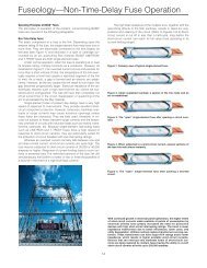
<strong>Selective</strong> <strong>Coordination</strong>FusesFor the next example, the Selectivity Ratio Guide suggests that the minimumratio between line side and load side fuse should be at least 2:1. The one-lineshows Low-Peak ® fuses KRP-C-1000SP feeding a LPS-RK-200SP. The ratioof amp ratings is 5:1 (1000:200) which indicates coordination between thesefuses. Continuing further into the system the LPS-RK-200SP feeds aLPJ-60SP. This ratio of amp ratings is 3.33:1 (200:60), which also indicatesa selectively coordinated system.I pAvailableShort-Circuit Current480/277VI 1 pKRP-C-1000SPAmp FuseLet Through EnergyLine SideLoad SideLow-PeakTime-Delay FuseKRP-C-1000SPt mt ct aLow-PeakLPS-RK-200SPDual-Element FuseLPS-RK-200SPAmp FuseLet Through EnergyLine SideLoad Sidet mt ct cLow-PeakLPJ-60SPDual-Element FuseFaultLPJ-60SPAmp FuseLet Through Energy*Requirements for selectivity—Total clearing energy of load side fuse is less than melting energy of line side fuse.*Area under the curves is not actual energy but is indicative of let-through energy. Actual let-through energy is I 2 rt.92 ©2005 <strong>Cooper</strong> <strong>Bussmann</strong>
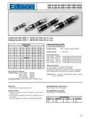
<strong>Selective</strong> <strong>Coordination</strong>Circuit BreakersMedium to High Level Fault Currents–Circuit BreakersThe following curve illustrates a 400A circuit breaker ahead of a 90A breaker.Any fault above 1500A on the load side of the 90A breaker will open bothbreakers. The 90A breaker will generally unlatch before the 400A breaker.However, before the 90A breaker can separate its contacts and clear the faultcurrent, the 400A breaker has unlatched and also will open.Assume a 4000A short circuit exists on the load side of the 90A circuit breaker.The sequence of events would be as follows:100080060040030020010080604030400A90A4000A1. The 90A breaker will unlatch (Point A) and free the breaker mechanism to startthe actual opening process.2. The 400A breaker will unlatch (Point B) and it, too, would begin the openingprocess. Once a breaker unlatches, it will open. At the unlatching point, theprocess is irreversible.3. At Point C, the 90A breaker will have completely interrupted the fault current.4. At Point D, the 400A breaker also will have completely opened the circuit.Consequently, this is a non-selective system, causing a complete blackout tothe other loads protected by the 400A breaker.As printed by one circuit breaker manufacturer, “One should not overlook thefact that when a high fault current occurs on a circuit having several circuitbreakers in series, the instantaneous trip on all breakers may operate.Therefore, in cases where several breakers are in series, the larger upstreambreaker may start to unlatch before the smaller downstream breaker hascleared the fault. This means that for faults in this range, a main breaker mayopen when it would be desirable for only the feeder breaker to open.” This istypically referred to in the industry as a "cascading effect."Typically circuit breaker manufacturers do not publish the unlatching times orunlatching curves for their products.TIME IN SECONDS2010864321.8.6.4.3.2.1.08.06.04.03.02.01.008.006.004.00390AmpCircuit Breaker400Amp Circuit BreakerI.T. = 5XD•C•B•A•.002.001102030406080100200300400600800100020001,500ACURRENT IN AMPERES30004,000A6000800010,00020,00030,00040,00060,00080,000100,00014,000A 30,000AI.R. I.R.©2005 <strong>Cooper</strong> <strong>Bussmann</strong>95
<strong>Selective</strong> <strong>Coordination</strong>Circuit BreakersSimple Method To CheckCircuit Breaker <strong>Coordination</strong>The previous discussion and curve illustrated two molded case circuit breakers(90A and 400A) with the unlatching characteristics for both shown on onecurve. This illustrated that two circuit breakers with instantaneous trips can notbe selectively coordinated for fault currents above a certain level. That level isthe fault current at which the upstream circuit breaker operates in itsinstantaneous trip region. When a fault above that level occurs, the lowercircuit breaker (90A in this case) unlatches. However, before it clears thecircuit, the upstream circuit breaker(s) (400A in this case) also unlatches.Once a circuit breaker unlatches, it will open, thereby disconnecting the circuitfrom the power source. In the case shown, the curves show the 400A circuitbreaker needlessly opens for a fault on the load side of the 90A circuitbreaker. For any fault current greater than where the two circuit breakercurves intersect (in this case 1500A) the upstream circuit breaker does notcoordinate with the down stream circuit breaker.However, in most cases, manufacturers do not publish unlatching times orunlatching curves for their circuit breakers. Therefore, even the most detailedcoordination study from a software program will NOT show whether or not acircuit breaker system is "selectively coordinated." So then, how cancoordination of circuit breakers be assessed when all the circuit breakers usedin a system have instantaneous trip settings? There is a very simple methodthat does not even require drawing the circuit breaker time current curves.This method can be used to analyze software program coordination plots inmost cases. The following paragraphs present this method.Circuit Breaker <strong>Coordination</strong> —Simplified Method With Time Current CurveWith the simplified method, there is no need to have the unlatching times ordraw the unlatching curves. The following curve illustrates the time currentcharacteristics for the 1200A circuit breaker, the 400A circuit breaker and 100Acircuit breaker. The instantaneous trip settings for each of these three moldedcase circuit breakers are provided on the one-line diagram. The 100A circuitbreaker has a non-adjustable instantaneous trip setting and the curve is asdepicted. The 400A circuit breaker has an instantaneous trip set at 10 times itsamp rating (10X) which is 10 times 400A or 4000A. The 1200A circuit breakerhas an instantaneous trip set at six times its amp rating (6X) which is six times1200A rating or 7200A.. Remember from a previous section “2. InstantaneousRegion” that there is a tolerance associated with the instantaneous trip regionfor adjustable instantaneous trip settings; the curve shown for the 400A and1200A circuit breakers are drawn with the tolerances included.1. This simple method will be shown with the time current curves (but without theunlatching time curves included).2. However, normally it is not even necessary to draw the time current curves inorder to evaluate coordination of circuit breakers having instantaneous trip units.So another section provides this simplified method without needing a time currentcurve.Below is the one line diagram that will be used for learning these simplemethods. Review the one-line diagram below that has three molded casecircuit breakers in series: from the main 1200A to the 100A branch circuit withthe 400A feeder in between. The other circuit breakers on the one-linediagram supply other circuits and loads. The fault current path from the powersource is depicted by the red arrows/lines superseded on the one-linediagram.One-Line For CircuitBreaker System<strong>Coordination</strong>Analysis1200A MCCBIt @ 6 X = 7,200A400A MCCBIt @ 10 X = 4,000A100A MCCBIt Non-AdjustableFault > 7,200AWhen the curves of two circuit breakers cross over in their instantaneous tripregion, then the drawing indicates that the two circuit breakers do notcoordinate for fault currents greater than this cross over point.For instance, interpreting the coordination curves for the 100A circuit breakerand the 400A circuit breaker: their curves intersect in the instantaneous regionstarting at approximately 3600A. That means for a fault current greater than3600A on the load side of the 100A circuit breaker, the 400A circuit breakerwill open as well as the 100A circuit breaker. This demonstrates a lack ofcoordination and results in a "cascading effect" that will cause a partialblackout.This curve also shows that for any fault greater than approximately 6500 ampson the load side of the 100A circuit breaker, the 400A and 1200A circuitbreakers will open as well as the 100A circuit breaker. The reason: for a faultof greater than 6500A, all three of these circuit breakers are in theirinstantaneous trip region. Both the 400A and 1200A circuit breakers can96 ©2005 <strong>Cooper</strong> <strong>Bussmann</strong>
<strong>Selective</strong> <strong>Coordination</strong>Circuit Breakersunlatch before the 100A circuit breaker clears the fault current. If this is notunderstood, re-read the previous section “Circuit Breaker <strong>Coordination</strong> -Medium to High Level Fault Currents.”How does this affect the electrical system? Look at the one-line diagrambelow. For any fault current greater than approximately 6500A on the load sideof the 100A circuit breaker, the 1200A and 400A circuit breakers open as wellas the 100A circuit breaker. The yellow shading indicates that all three circuitbreakers opened - 100A branch circuit, 400A feeder and the 1200A main. Inaddition, all the loads fed by the other circuit breakers, denoted by the hashshading, are blacked out unnecessarily. This is due to the lack of coordinationbetween the 100A, 400A and 1200A circuit breakers.Circuit Breaker <strong>Coordination</strong> — Simplified MethodWithout Time Current CurveIt is not even necessary to draw the curves to assess circuit breakercoordination. All that is necessary is to use some simple multiplication. Multiplythe instantaneous trip setting times the circuit breaker amp rating (theinstantaneous trip setting is usually adjustable but can vary depending uponframe size and circuit breaker type - some have adjustable settings of four to10 times the amp rating - check specifications of specific circuit breaker). Theproduct of these two is the approximate point at which a circuit breaker entersits instantaneous trip region. (As explained in a previous section “2.Instantaneous Region”, there is a tolerance associated with where theinstantaneous trip initially picks up. A vertical band depicts the instantaneoustrip pickup tolerance. For this easy method, we will ignore the tolerance band;therefore the results differ somewhat from the time current curve example justgiven.)For instance, the 400A circuit breaker in this example has its instantaneoustrip (IT) set at 10 times its amp rating (10X). Therefore for fault currents above10 x 400A or 4000A, the 400A circuit breaker will unlatch in itsinstantaneous trip region, thereby opening.The same could be determined for the 1200A circuit breaker, which has itsinstantaneous trip set at 6X its amp rating. Therefore, for fault currents above7200A, the 1200A circuit breaker unlatches in its instantaneous trip region,thereby opening.The coordination analysis of the circuit breakers merely requires knowing whatthe numbers mean:1. Any fault on the loadside of the 100A circuit breaker greater than 4000A will openthe 400A circuit breaker as well as the 100A circuit breaker. Reason: the 400Acircuit breaker with an instantaneous trip set at 10 times opensinstantaneously for any fault current greater than 4000A.2. Any fault on the loadside of the 100A circuit breaker greater than 7200A will openthe 1200A circuit breaker as well as the 100A and 400A circuit breakers. Reason:the 1200A circuit breaker with an instantaneous trip set at six times opensinstantaneously for any fault current greater than 7200A.3. Any fault on the loadside of the 400A circuit breaker greater than 7200A will openthe 1200A circuit breaker as well as the 400A circuit breaker. Reason: the 1200Acircuit breaker with an instantaneous trip set at six times opens instantaneouslyfor any fault current greater than 7200A.So it becomes apparent, to evaluate coordination of circuit breakers withinstantaneous trips, the time current curves do not have to be drawn. All that isnecessary is to use simple multiplication of the instantaneous trip settingstimes the circuit breaker amp ratings,and evaluate this in conjunction with theavailable fault current.Note: Circuit breakers that provide the use of a short time delay do not alwaysassure coordination. The reason is that molded case circuit breakers andinsulated case circuit breakers that have a short-time delay will also have aninstantaneous trip setting that overrides the short-time delay at some faultlevel. Molded case circuit breakers with short time delay settings will have aninstantaneous trip that overrides the short time delay, typically at a maximumof 10 times the amp rating. These instantaneous overrides are necessary toprotect the circuit breakers for higher faults. The same simple procedure forevaluating circuit breakers with instantaneous trips can be used for this typecircuit breaker, also. Merely read the manufacturer’s literature to determinethis instantaneous trip override setting. However, be certain to establish if theinstantaneous trip pickup is given in symmetrical amps or asymmetrical amps.Some manufacturers specify the instantaneous override in asymmetrical ampswhich for practical evaluation purposes moves the instantaneous trip pickupsetting to the left (picks up at lower symmetrical fault currents than perceived).See the next two pages for a brief discussion and curves of short-time delaysettings and instantaneous overrides.©2005 <strong>Cooper</strong> <strong>Bussmann</strong>97
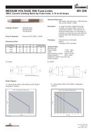
<strong>Selective</strong> <strong>Coordination</strong>Circuit BreakersShort-Time-Delay and Instantaneous OverrideSome circuit breakers are equipped with short-time delay settings for the solepurpose of improving system coordination. Review the three curves on thispage and the next page.Circuit breaker short-time-delay (STD) mechanisms allow an intentional delayto be installed on low voltage power circuit breakers. Short-time-delays allowthe fault current to flow for several cycles, which subjects the electricalequipment to unnecessarily high mechanical and thermal stress. Mostequipment ratings, such as short circuit ratings for bus duct and switchboardbus, do not apply when short-time-delay settings are employed. The use ofshort-time-delay settings on circuit breakers requires the system equipment tobe reinforced to withstand the available fault current for the duration of theshort-time-delay. Ignoring equipment ratings in relation to the protective deviceopening time and let-through characteristics can be disastrous. Following is atime-current curve plot for two low voltage power circuit breaker withshort-time delay and a 20A MCCB. The 100A CB has a STD set at 6 cyclesand the 800A CB has a STD set at 24 cycles. This type of separation of thecurves should allow for selective coordination, assuming that the breakershave been serviced and maintained per the manufacturer's requirements. Thisis an approach to achieve selective coordination that can diminish electricalsafety and component protection.An insulated case circuit breaker (ICCB) may also be equipped with shorttime-delay.However, ICCBs will have a built-in override mechanism. This iscalled the instantaneous override function, and will override the STD formedium to high level faults. This override may “kick in” for faults as low as 12times (12x) the breaker’s amp rating. (See curve in left column on next page.)This can result in non-selective tripping of the breaker and load side breakerswhere overlaps occur. This can be seen in the example. (See curve in rightcolumn on next page.) As the overlap suggests, for any fault condition greaterthan 21,000A, both devices will open, causing a blackout.Zone-<strong>Selective</strong> InterlockingZone-<strong>Selective</strong> Interlocking (ZSI), or zone restraint, has been available sincethe early 1990s. ZSI is designed to limit thermal stress caused by shortcircuitson a distribution system. ZSI will enhance the coordination of theupstream and downstream molded case circuit breakers for all values ofavailable short-circuit current up to the instantaneous override of the upstreamcircuit breaker.Caution: Use of Circuit Breaker Short-TimeDelay Settings May Negate Protection andIncrease Arc-Flash HazardThe longer an overcurrent is permitted to flow the greater the potential forcomponent damage. The primary function of an overcurrent protective deviceis to provide protection to circuit components and equipment. A short-timedelay (STD) setting on a circuit breaker can negate the function of protectingthe circuit components. A low voltage power circuit breaker with a short-timedelay and without instantaneous trip, permits a fault to flow for the length oftime of the STD setting, which might be 6, 12, 18, 24 or 30 cycles. Thistypically is done to achieve fault coordination with downstream circuitbreakers. However, there is an adverse consequence associated with usingcircuit breaker short-time delay settings. If a fault occurs on the circuitprotected by a short time delay setting, a tremendous amount of damagingfault energy can be released while the system waits for the circuit breakershort-time delay to time out.In addition, circuit breakers with short-time delay settings can drasticallyincrease the arc-flash hazard for a worker. The longer an overcurrentprotective device takes to open, the greater the flash hazard due to arcingfaults. Research has shown that the arc-flash hazard can increase with themagnitude of the current and the time duration the current is permitted to flow.System designers and users should understand that using circuit breakerswith short-time delay settings will greatly increase the arc-flash energy if anarcing fault incident occurs. If an incident occurs when a worker is at or nearthe arc-flash, the worker may be subjected to considerably more arc-flashenergy than if an instantaneous trip circuit breaker or better yet a currentlimitingcircuit breaker or current-limiting fuses were protecting the circuit. Therequirements for doing flash hazard analysis for worker safety are found inNFPA 70E “Electrical Safety Requirements for Employee Workplaces."As an example, compare the photos resulting from investigative testing ofarcing faults. Further information is provided in “Electrical Safety & Arc-FlashProtection” in this bulletin. A couple of comparison photos are shown on thenext page. These tests and others are detailed in “Staged Tests IncreaseAwareness of Arc-Fault Hazards in Electrical Equipment”, IEEE Petroleum andChemical Industry Conference Record, September, 1997, pp. 313-322. Thispaper can be found on the <strong>Cooper</strong> <strong>Bussmann</strong> web site atwww.cooperbussmann.com/services/safetybasics. One finding of this IEEEpaper is that current-limiting overcurrent protective devices reduce damageand arc-fault energy (provided the fault current is within the current-limitingrange).Low Voltage Power Circuit Breaker with Short-Time-Delay98 ©2005 <strong>Cooper</strong> <strong>Bussmann</strong>
<strong>Selective</strong> <strong>Coordination</strong>Circuit BreakersInsulated Case Circuit Breaker–Instantaneous OverrideInstantaneous Override Opens at 21,000 Amps100080060040030010008006004003002000A200200100A10010080806040ICCB6040100A CB2000A ICCB30302020108643TIME IN SECONDS108643TIME IN SECONDS21.8.621.8.6.4.3.4.3.2.1.08.06InstantaneousOverride= 12X.2.1.08.06.04.03.04.03BLACKOUT!.02.02.0110020030040060080010002000300040006000800010,000CURRENT IN AMPERES20,00030,00040,00060,00080,000100,000.0110020030040060080010002000300040006000800010,000CURRENT IN AMPERES20,00030,00040,00021,000 AMPS60,00080,000100,000Test 4 shows sequential photos of a circuit protected by a circuit breaker with ashort-time delay: interrupted at 6 cycles, so this incident lasted 1 ⁄10 of a second. Thearcing fault was initiated on a three phase, 480V system with 22,600A shortcircuit available.Current-limiting fuses or current-limiting circuit breakers can reduce the risksassociated with arc-flash hazards by limiting the magnitude of the faultcurrents (provided the fault current is within the current-limiting range) andreducing the time duration of the fault. Test 3 photos, to the right, are fromtests with the same test setup as shown in Test 4 above, except that KRP-C-601SP Low-Peak current-limiting fuses protect the circuit and clear the arcingfault in less than 1 ⁄2 cycle. The arc-flash was greatly reduced because thesefuses were in their current-limiting range. Also, the thermal and mechanicalstresses on the circuit components that conducted the fault current wereTest 3 – Same test circuit as the prior photos, to the left, except the circuit isprotected by KRP-C-601SP <strong>Cooper</strong> <strong>Bussmann</strong> Low-Peak ® Current-Limiting Fuses. Inthis case these fuses limited the current and the fuses cleared in less than a 1 ⁄2 cycle.greatly reduced. Recent arc-flash research has shown that arc-flash energy islinearly proportional to the time duration of the fault (given the fault currentsare the same). Ignoring the fact that the KRP-C-601SP Low-Peak fuses inTest 3 limited the current let-through, the arc-flash energy released in Test 3was approximately 1 ⁄12 that of Test 4 just due to the faster operation of the KRP-C-601SP Low-Peak fuses (less than 1 ⁄2 cycle clearing in Test 3 vs. 6 cyclesclearing in Test 4). The actual arc-flash energy was reduced even more in Test3 because of the current-limiting effect of the KRP-C-601SP Low-Peak fuses.©2005 <strong>Cooper</strong> <strong>Bussmann</strong>99
<strong>Selective</strong> <strong>Coordination</strong>Essential Electrical Systems In Healthcare Facilities, Emergency Systems and LegallyRequired Standby SystemsIn recent history, there has been an increasing demand for reliability ofelectrical power for buildings spanning the entire spectrum from single-familyresidences to places of assembly to industrial facilities. Many buildingsystems have gone to the extent of installing emergency back-up or standbysystems to ensure maximum possible reliability and continuity of theirelectrical system. There are some types of buildings that require an emergencysystem or legally required standby system such as hotels, theatres,sports arenas, healthcare facilities and many more similar institutions. Theselife safety electrical systems are used to ensure electrical power in the case ofpower loss due to an outside source (utility loss) or an inside source(overcurrent condition). Very important loads must remain energized as longas possible during times of normal power outage and emergencies that maybe caused by equipment failures, nature or man. However, simply installing aback-up system is not the entire solution, the electrical system must bedesigned to maximize power to these important loads and minimize outageseven under physical catastrophes. It is very important to analyze thecharacteristics of the overcurrent protective devices (OCPDs) of these lifesafety systems to ensure they will perform as desired.The NEC ® has special requirements for these life safety electrical systems.These include several requirements that are based upon providing a systemwith reliable operation, reducing the probability of faults, and minimizing theeffects of an outage to the smallest portion of the system as possible. Beloware a few of these sections:• 700.4 maintenance and testing requirements• 700.9(B) emergency circuits separated from normal supply circuits• 700.9(C) wiring specifically located to minimize system hazards• 700.16 failure of one component must not result in a condition where ameans of egress will be in total darkness.The objective of these requirements is to ensure system uptime with the goalof safety of human life during emergencies or for essential health carefunctions.The 2005 NEC® has adapted to this demand and has modified a few articlesto address the issue of selective coordination and to ensure by design andinstallation that the intended life safety electrical systems will stay in servicefor the longest possible period of time.The installation of a back-up system could easily be negated by the use ofovercurrent protective devices that are not selectively coordinated. <strong>Selective</strong>coordination helps ensure by design and installation that some life safetyelectrical systems will stay in service for the longest possible period of time.There has been a requirement for selective coordination in the NEC ® for manyyears. NEC ® 620.62 has had a selective coordination requirement for multipleelevators in a building. This requirement is crucial for a few specific reasonssuch as not stranding passengers for normal operation and for emergencyegress as well as keeping elevators in use for emergency firefightingoperations. The 2005 NEC ® selective coordination requirements have beenexpanded and a definition <strong>Coordination</strong> (<strong>Selective</strong>) has been added to Article100:New Article 100 Definition<strong>Coordination</strong> (<strong>Selective</strong>). Localization of an overcurrent condition to restrictoutages to the circuit or equipment affected, accomplished by the choice ofovercurrent protective devices and their ratings or settings.NEC ® 700.27 (Emergency Systems) and 701.18 (Legally Required StandbySystems) have added selective coordination of overcurrent protective devicesto help ensure life safety. Examples of circuits that require selectivecoordination would be emergency and egress lighting for the safe evacuationfrom a building and to assist in crowd and panic control. Also, in many cases,some elevators and ventilation equipment may be classified as an emergencyor legally required standby system by the “Authority Having Jurisdiction” (AHJ)or the locally adopted building code. Also, 527.26 requires the essentialelectrical systems of healthcare facilities have overcurrent protective devicesthat are selectively coordinated.The New NEC ® Requirements517.26 Application of Other Articles. The essential electricalsystem shall meet the requirements of Article 700, except asamended by Article 517.700.27 <strong>Coordination</strong>. Emergency system(s) overcurrent devicesshall be selectively coordinated with all supply side overcurrentprotective devices.701.18 <strong>Coordination</strong>. Legally required standby system(s)overcurrent devices shall be selectively coordinated with all supplyside overcurrent protective devices.System RequirementAs stated in the NEC ® requirements above, selective coordination is not justbetween the branch circuit and feeder. It is the entire circuit path from themain overcurrent protective device to the branch circuit device. See figurebelow.100 ©2005 <strong>Cooper</strong> <strong>Bussmann</strong>
<strong>Selective</strong> <strong>Coordination</strong>Essential Electrical Systems In Healthcare Facilities, Emergency Systems and LegallyRequired Standby SystemsA given emergency branch circuit load has a circuit path up through to themain on the normal source and another circuit path up through to the main onthe emergency source. The requirement for selective coordination means thatall the overcurrent protective devices must be selectively coordinated witheach other, from each emergency branch circuit up through to the main of thenormal power supply and up through to the main on the emergency powersupply. See following example:3. A coordination study should fully investigate, interpret, and present thelevel of coordination achieved for the full system and for the determinedamount of available short-circuit currents. This requires a person qualified forthis task. Too often, coordination studies are performed where the deliverable isjust time current curve plots with no interpretation or discussion on the level ofcoordination achieved (or sacrificed). Also, the studies should be performed in thedesign phase so that if the study results prompt a change, the change can bewithout major ramifications.Fusible Systems<strong>Cooper</strong> <strong>Bussmann</strong> makes it easy to design fusible systems that are selectivelycoordinated. For the modern current-limiting fuses, selectivity ratios arepublished (see Fuse Selectivity Ratio Guide section). It is not necessary to plottime current curves or do a short-circuit current analysis; all that is necessaryis to make sure the fuse types and ampere rating ratios for the mains, feedersand branch circuit meet or exceed the selectivity ratio. These selectivity ratiosare for all levels of overcurrent up to the interrupting ratings of the respectivefuses. The ratios are valid even for fuse opening times less than 0.01seconds. This means with current-limiting fuses, it is not necessary to do anyanalysis for less than 0.01 seconds when the fuse types and ampere ratingratios adhere to the selectivity ratios. The industry standard for publishing fusetime current curves is to plot the times from 0.01 seconds and longer. Thefollowing example illustrates all that is necessary to achieve selectivecoordination with a fusible system.How Can <strong>Selective</strong> <strong>Coordination</strong> Be Achieved?<strong>Selective</strong> coordination of the overcurrent protective devices for these lifesafety systems for both the normal power source path and the alternate powersource path can be achieved with either modern current-limiting fusetechnology or modern circuit breaker technology. However, not all fuse typesor circuit breaker types can be used in any and all situations to ensureselective coordination. The ability to achieve selective coordination dependson the specific circuit parameters (short-circuit currents available at variouspoints in the system) and the fuse or circuit breaker opening characteristicsand possible setting options. Proper overcurrent protective device choice andselective coordination analysis is absolutely necessary. However, if the properchoices and analysis are not made so that selective coordination is ensured,the system may be built with deficiencies that may negatively impact lifesafety.Other Important Considerations1. Either a system has overcurrent protective devices that are selectivelycoordinated or the system does not. There is no middle ground. When termssuch as “enhancing” coordination, “optimizing” coordination, coordination "to thebest degree possible," or similar terms are used, it generally means theovercurrent protective devices are not selectively coordinated over the full rangeof short-circuit currents that are available in the application.2. <strong>Selective</strong> coordination is for the full range of overcurrents available at allmains, feeders and branch circuits. It is not acceptable to arbitrarily considerselective coordination is applicable only above certain times such as 0.01, 0.1, or1.0 seconds. The coverage of selective coordination in the sections on <strong>Selective</strong><strong>Coordination</strong> for Fuses and Circuit Breakers of this SPD publication explains howto assess fuses and circuit breakers for the full range of overcurrents irrespectiveof the times. Also, these preceding sections provide some easy, quick methods toassess selective coordination for both fuse and circuit breaker systems.©2005 <strong>Cooper</strong> <strong>Bussmann</strong>101
<strong>Selective</strong> <strong>Coordination</strong>Essential Electrical Systems In Healthcare Facilities, Emergency Systems and LegallyRequired Standby SystemsFrequently Asked Questions: Fuse SystemQ. How about when two different current-limiting fuses are plotted on a timecurrent curve and there is a space between the lower ampere fuse total clearcurve and the larger ampere fuse minimum melt curve – does this ensureselective coordination (if the selectivity ratio is not known)?A. In this case, without knowing the selectivity ratio and having only timecurrent curves, selective coordination can only be ensured for the level ofovercurrent up to the point where the larger fuse curve crosses 0.01 seconds.For times where the fuse opening time is less than 0.01 seconds, selectivityratios are necessary. It is not necessary to plot fuse time current curves; justadhere to the selectivity ratios.Q. What about lighting branch circuits? There has not been a commerciallyavailable fusible lighting panelboards, so how can selective coordination beachieved for the 20A panelboard circuits?A. In order to achieve a selectively coordinated fusible system, <strong>Cooper</strong><strong>Bussmann</strong> has the <strong>Coordination</strong> Module, which is a fusible branch circuitpanelboard. So now it is easy to achieve selective coordination from main tobranch circuit with an all fusible system, including branch circuit lightingpanelboards, by adhering to the simple selectivity ratios. Information on<strong>Coordination</strong> Module on www.cooperbussmann.com data sheet 3115.Selectivity Ratio Guide For <strong>Coordination</strong> ModuleLoad-Side FuseLP-CCFNQ-RKTK-RLine-Side FuseLPJ_SP 2:1LPN-RK_SP 2:1LPS-RK_SP 2:1FRN-R 2:1FRS-R 2:1Ratios only apply to <strong>Cooper</strong> <strong>Bussmann</strong> Fuses. When fuses are in the same case size, consult<strong>Cooper</strong> <strong>Bussmann</strong>.102 ©2005 <strong>Cooper</strong> <strong>Bussmann</strong>
<strong>Selective</strong> <strong>Coordination</strong>Essential Electrical Systems In Healthcare Facilities, Emergency Systems and LegallyRequired Standby SystemsCircuit Breaker SystemsAs stated earlier, if a designer wants to use circuit breakers, it may be possibleto achieve a selectively coordinated system. There are a host of circuitbreaker alternatives in the form of circuit breaker types, optional features, andpossible settings. See Circuit Breaker <strong>Coordination</strong> section in this publicationfor more in-depth discussion on some of the options and tradeoffs. Thedesigner must understand the characteristics, setting options and overrideparticulars for each circuit breaker considered and in some cases, factor in thespecific circuit parameters such as the available short-circuit currents at eachpoint in the system.If circuit breakers are considered, typically the following become important:1. A short-circuit current study with a coordination study (interpreted properly) isnecessary to determine if selective coordination is achieved for each circuit andfor the entire circuit path. It is necessary to have the available short-circuitcurrents and circuit breakers’ characteristics and settings. Depending on thecircumstances, the designer may have to use different type circuit breakers oroptions in order to achieve selective coordination.2. Typically the designer will have to utilize circuit breakers with short-time delaysand possibly larger frame sizes. This may increase the cost and equipment size.3. Tradeoffs in system protection: These decisions that may improve the level ofcoordination may negatively impact the level of component protection.4. Arc flash hazard level: These decisions that may improve the level of coordinationmay negatively impact the arc flash hazard level.5. In many cases, the circuit breaker solution may only be selectively coordinated forthe exact designed system (for specific circuit breaker settings and available shortcircuit currents of a specific system). Most systems get upgraded or change atsome point in time and this can significantly increase the available short-circuitcurrents. This may negate the selective coordination for some circuit breakersystems that may have originally been selectively coordinated.6. Testing and maintenance: periodic exercising and testing are important for circuitbreakers to ensure they operate as intended. If circuit breakers are found not tooperate as specified, maintenance or replacement of these circuit breakers isnecessary. For instance, if a feeder circuit breaker fails to operate or operatesslower than as specified, it may cause the main circuit breaker to open due to afeeder fault. The result would be a much larger portion of these critical systemloads being without power.System with Mixture of Fuses and Circuit BreakersFuses and circuit breakers operate in totally different ways. Fuses are thermaldevices that have encased fusible elements that operate under overcurrentconditions by melting or vaporizing at some points of the element, arcing, andclearing the circuit. All circuit breakers have three operating functions to cleara circuit: (1) overcurrent sensing, (2) unlatching, and (3) parting the contacts,arcing, and clearing. There are numerous technologies used for circuit breakerovercurrent sensing.For downstream fuse and upstream circuit breaker, it is not a simple matter todetermine if a fuse and circuit breaker will be selectively coordinated. Even ifthe plot of the time current curves for a downstream fuse and an upstreamcircuit breaker show that the curves do not cross, selective coordination maynot be possible.If a fuse is upstream and a circuit breaker is downstream, at some point thefuse time current characteristic crosses the circuit breaker time currentcharacteristic. For short-circuit currents at that point and higher, the upstreamfuse is not coordinated with the down stream circuit breaker.New Requirement ComplianceAchieving overcurrent protective device selective coordination for a systemrequires the proper engineering, specification and installation of the requireddevices, and in addition, knowledgeable plan review and inspection to ensurecompliance. The designer, contractor, and plan review/inspector each havetheir role in compliance to selective coordination in order to ensure safety tohuman life.Role of DesignersFor these vital systems, the designer must select, specify, and documentovercurrent protective devices that achieve selective coordination for the fullrange of possible overcurrents and for faults at all possible points in thesystem (faults can occur in the branch circuits, sub-feeders, and feeders). Thedesigner should provide the plan reviewer a stamped analysis verifying thatselective coordination is achieved as designed for the required electricalsystems. Documentation of the basis should be included. Also, this informationis necessary so that the contractor quotes and installs the overcurrentprotective devices as designed.Role of Plan Review/InspectorsThe plan review process is a critical phase. If a non-compliant design does notget caught and corrected in the plan review, it could get red tagged in theinspection phase, which may require a very expensive gear change out.During the plan review process, the engineer must provide the stampedsubstantiation in the form of documentation that his design achieves selectivecoordination for these vital circuits. The plan reviewer should not have toprove or disprove that selective coordination is achieved. The engineer’sdocumentation should be clear enough to demonstrate that the design workincluded the proper selective coordination analysis and that the plans andspecifications clearly articulate the required details on type of overcurrentprotective devices, ampere ratings, and settings (if circuit breakers). Theengineer’s documentation should clearly state that the plans specifyovercurrent protective devices that achieve selective coordination for thesevital systems.During the inspection process, prior to energizing the system, the fieldinspection should include verifying that the overcurrent protective deviceshave been installed as specified. If circuit breakers are used, the settingsshould be verified as per plan.Role of ContractorsContractors must install the system as designed to ensure selectivecoordination for the system. If a fusible system, install the fuse types andampere ratings as called for in the design. If a circuit breaker system,install the circuit breaker types with the specified settings.If the contractor opts to suggest a value engineering option for these vitalsystems, it is critical that the engineer evaluates and approves of any changesas well as the plan reviewer.©2005 <strong>Cooper</strong> <strong>Bussmann</strong>103
<strong>Selective</strong> <strong>Coordination</strong>Elevator CircuitElevator Circuits and RequiredShunt Trip Disconnect — A Simple Solution.When sprinklers are installed in elevator hoistways, machine rooms, ormachinery spaces, ANSI/ASME A17.1 requires that the power be removed tothe affected elevator upon or prior to the activation of these sprinklers. This isan elevator code requirement that affects the electrical installation. Theelectrical installation allows this requirement to be implemented at thedisconnecting means for the elevator in NEC ® 620.51(B). This requirement ismost commonly accomplished through the use of a shunt trip disconnect andits own control power. To make this situation even more complicated, interfacewith the fire alarm system along with the monitoring of components requiredby NFPA 72 must be accomplished in order to activate the shunt trip actionwhen appropriate and as well as making sure that the system is functionalduring normal operation. This requires the use of interposing relays that mustbe supplied in an additional enclosure. Other requirements that have to be metinclude selective coordination for multiple elevators (620.62) and hydraulicelevators with battery lowering [620.91(C)].There is a simple solution available for engineering consultants, contractors,and inspectors to help comply with all of these requirements in one enclosurecalled the <strong>Cooper</strong> <strong>Bussmann</strong> Power Module.Elevator <strong>Selective</strong> <strong>Coordination</strong> RequirementIn the 2005 NEC ® , 620.62 states:Where more than one driving machine disconnecting means is suppliedby a single feeder, the overcurrent protective devices in eachdisconnecting means shall be selectively coordinated with any othersupply side overcurrent protective devices.A design engineer must specify and the contractor must install main, feeder,sub-feeder, and branch circuit protective devices that are selectivelycoordinated for all values of overloads and short circuits.To better understand how to assess if the overcurrent protective devices in anelectrical system are selectively coordinated refer to the <strong>Selective</strong><strong>Coordination</strong> Section of this booklet. Below is a brief coordination assessmentof an elevator system in a circuit breaker system (example 1) and in a fusesystem (Example 2).Power Module Elevator DisconnectAll-in-One Solution for Three DisciplinesNEC ®• <strong>Selective</strong> <strong>Coordination</strong>• Hydraulic Elevators• Traction ElevatorsNFPA 72• Fire Safety Interface• Component MonitoringANSI/ASME A17.1• Shunt TripRequirementThe Power Module contains a shunt trip fusible switch together with thecomponents necessary to comply with the fire alarm system requirements andshunt trip control power all in one package. For engineering consultants thismeans a simplified specification. For contractors this means a simplifiedinstallation because all that has to be done is connecting the appropriatewires. For inspectors this becomes simplified because everything is in oneplace with the same wiring every time. The fusible portion of the switch utilizesLow-Peak LPJ-(amp)SP fuses that protect the elevator branch circuit from thedamaging effects of short-circuit currents as well as helping to provide an easymethod of selective coordination when supplied with an upstream Low-Peakfuse with at least a 2:1 amp rating ratio. More information about the <strong>Cooper</strong><strong>Bussmann</strong> Power Module can be found at www.cooperbussmann.com.Using the one-line diagram above, a coordination study must be done to seethat the system complies with the 620.62 selective coordination requirement ifEL-1, EL-2, and EL-3 are elevator motors.Go to the <strong>Selective</strong> <strong>Coordination</strong> section for a more indepth discussion on howto analyze systems to determine if selective coordination can be achieved.104 ©2005 <strong>Cooper</strong> <strong>Bussmann</strong>
<strong>Selective</strong> <strong>Coordination</strong>Elevator CircuitExample 1 Circuit Breaker SystemIn this example, molded case circuit breakers (MCCB) will be used for thebranch and feeder protective devices and an insulated case circuit breaker(ICCB) will be used for the main protective device.1,000800600Example 2 Fusible SystemIn our second example, LPJ-(amp)SP fuses will be used for the branchprotection, LPS-RK-(amp)SP fuses will be used for the feeder protection, andKRP-C-(amp)SP fuses will be used for the main protection.1,000800600400300200400300200KRP-C-1600SP10080601600A ICCB1008060LPS-RK-400SPTIME IN SECONDS40302010864321.8.6.4.3400A MCCB200A MCCB100A MCCBTIME IN SECONDS40302010864321.8.6.4LPS-RK-200SPLPJ-100SP.2.3.2.1.08.06.04.03.1.08.06.04.02.03.01.021002003004006008001,0002,0003,0004,0006,0008,00010,000BLACKOUT(PARTIAL)CURRENT IN AMPERES20,00030,00040,00060,00080,000100,000BLACKOUT(TOTAL).011002003004006008001,0002,0003,0004,0006,0008,000CURRENT IN AMPERES10,00020,00030,00040,00060,00080,000100,000Looking at the time current curves for the circuit breaker in the figure above,where any two circuit breaker curves overlap is a lack of selectivecoordination. The overlap indicates both devices open. If any fault currentgreater than 750A and less than 3100A occurs at EL-1, EL-2 or EL-3, the200A circuit breaker will open as well as the 100A branch circuit breaker - thisis not a selectively coordinated system and does not meet the requirements of620.62. This lack of selective coordination could result in stranding passengersin elevators or not having elevators available for fire fighters. Fault currentsabove 3100A will open the 400A circuit breaker as well and faults aboveapproximately 16,000A will open the 1600A circuit breaker - which furtherillustrates the lack of coordination. For a better understanding of how toassess circuit breaker coordination, see the section on Circuit Breaker<strong>Coordination</strong> in this book. A system that is not in compliance may result inneedlessly stranding passengers and creating a serious safety hazard.To verify selective coordination, go no further than the Fuse Selectivity RatioGuide in the Fuse <strong>Selective</strong> <strong>Coordination</strong> section in this book. The Low-Peakfuses just require a 2:1 amp rating ratio to assure selective coordination. Inthis example, there is a 4:1 ratio between the main fuse (1600A) and the firstlevel feeder fuse (400A) and a 2:1 ratio between the first level feeder fuse andthe second level feeder fuse (200A). As well, there is a 2:1 ratio between thesecond level feeder fuse and the branch circuit fuse (100A). Since a minimumof a 2:1 ratio is satisfied at all levels for this system, selective coordination isachieved and 620.62 is met.As just demonstrated in the prior paragraph, the fuse time current curves donot have to be drawn to assess selective coordination. For illustrativepurposes, the time current curves for this example are shown above.©2005 <strong>Cooper</strong> <strong>Bussmann</strong>105