Selective Coordination - Cooper Bussmann
Selective Coordination - Cooper Bussmann
Selective Coordination - Cooper Bussmann

Create successful ePaper yourself
Turn your PDF publications into a flip-book with our unique Google optimized e-Paper software.
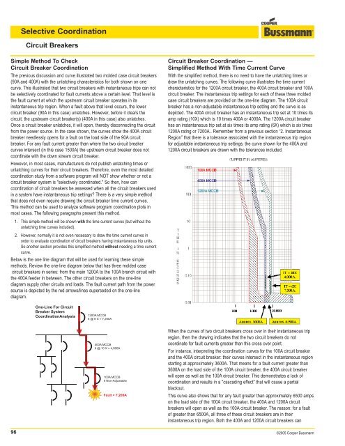
<strong>Selective</strong> <strong>Coordination</strong>Circuit BreakersSimple Method To CheckCircuit Breaker <strong>Coordination</strong>The previous discussion and curve illustrated two molded case circuit breakers(90A and 400A) with the unlatching characteristics for both shown on onecurve. This illustrated that two circuit breakers with instantaneous trips can notbe selectively coordinated for fault currents above a certain level. That level isthe fault current at which the upstream circuit breaker operates in itsinstantaneous trip region. When a fault above that level occurs, the lowercircuit breaker (90A in this case) unlatches. However, before it clears thecircuit, the upstream circuit breaker(s) (400A in this case) also unlatches.Once a circuit breaker unlatches, it will open, thereby disconnecting the circuitfrom the power source. In the case shown, the curves show the 400A circuitbreaker needlessly opens for a fault on the load side of the 90A circuitbreaker. For any fault current greater than where the two circuit breakercurves intersect (in this case 1500A) the upstream circuit breaker does notcoordinate with the down stream circuit breaker.However, in most cases, manufacturers do not publish unlatching times orunlatching curves for their circuit breakers. Therefore, even the most detailedcoordination study from a software program will NOT show whether or not acircuit breaker system is "selectively coordinated." So then, how cancoordination of circuit breakers be assessed when all the circuit breakers usedin a system have instantaneous trip settings? There is a very simple methodthat does not even require drawing the circuit breaker time current curves.This method can be used to analyze software program coordination plots inmost cases. The following paragraphs present this method.Circuit Breaker <strong>Coordination</strong> —Simplified Method With Time Current CurveWith the simplified method, there is no need to have the unlatching times ordraw the unlatching curves. The following curve illustrates the time currentcharacteristics for the 1200A circuit breaker, the 400A circuit breaker and 100Acircuit breaker. The instantaneous trip settings for each of these three moldedcase circuit breakers are provided on the one-line diagram. The 100A circuitbreaker has a non-adjustable instantaneous trip setting and the curve is asdepicted. The 400A circuit breaker has an instantaneous trip set at 10 times itsamp rating (10X) which is 10 times 400A or 4000A. The 1200A circuit breakerhas an instantaneous trip set at six times its amp rating (6X) which is six times1200A rating or 7200A.. Remember from a previous section “2. InstantaneousRegion” that there is a tolerance associated with the instantaneous trip regionfor adjustable instantaneous trip settings; the curve shown for the 400A and1200A circuit breakers are drawn with the tolerances included.1. This simple method will be shown with the time current curves (but without theunlatching time curves included).2. However, normally it is not even necessary to draw the time current curves inorder to evaluate coordination of circuit breakers having instantaneous trip units.So another section provides this simplified method without needing a time currentcurve.Below is the one line diagram that will be used for learning these simplemethods. Review the one-line diagram below that has three molded casecircuit breakers in series: from the main 1200A to the 100A branch circuit withthe 400A feeder in between. The other circuit breakers on the one-linediagram supply other circuits and loads. The fault current path from the powersource is depicted by the red arrows/lines superseded on the one-linediagram.One-Line For CircuitBreaker System<strong>Coordination</strong>Analysis1200A MCCBIt @ 6 X = 7,200A400A MCCBIt @ 10 X = 4,000A100A MCCBIt Non-AdjustableFault > 7,200AWhen the curves of two circuit breakers cross over in their instantaneous tripregion, then the drawing indicates that the two circuit breakers do notcoordinate for fault currents greater than this cross over point.For instance, interpreting the coordination curves for the 100A circuit breakerand the 400A circuit breaker: their curves intersect in the instantaneous regionstarting at approximately 3600A. That means for a fault current greater than3600A on the load side of the 100A circuit breaker, the 400A circuit breakerwill open as well as the 100A circuit breaker. This demonstrates a lack ofcoordination and results in a "cascading effect" that will cause a partialblackout.This curve also shows that for any fault greater than approximately 6500 ampson the load side of the 100A circuit breaker, the 400A and 1200A circuitbreakers will open as well as the 100A circuit breaker. The reason: for a faultof greater than 6500A, all three of these circuit breakers are in theirinstantaneous trip region. Both the 400A and 1200A circuit breakers can96 ©2005 <strong>Cooper</strong> <strong>Bussmann</strong>