<strong>Selective</strong> <strong>Coordination</strong>Circuit BreakersShort-Time-Delay and Instantaneous OverrideSome circuit breakers are equipped with short-time delay settings for the solepurpose of improving system coordination. Review the three curves on thispage and the next page.Circuit breaker short-time-delay (STD) mechanisms allow an intentional delayto be installed on low voltage power circuit breakers. Short-time-delays allowthe fault current to flow for several cycles, which subjects the electricalequipment to unnecessarily high mechanical and thermal stress. Mostequipment ratings, such as short circuit ratings for bus duct and switchboardbus, do not apply when short-time-delay settings are employed. The use ofshort-time-delay settings on circuit breakers requires the system equipment tobe reinforced to withstand the available fault current for the duration of theshort-time-delay. Ignoring equipment ratings in relation to the protective deviceopening time and let-through characteristics can be disastrous. Following is atime-current curve plot for two low voltage power circuit breaker withshort-time delay and a 20A MCCB. The 100A CB has a STD set at 6 cyclesand the 800A CB has a STD set at 24 cycles. This type of separation of thecurves should allow for selective coordination, assuming that the breakershave been serviced and maintained per the manufacturer's requirements. Thisis an approach to achieve selective coordination that can diminish electricalsafety and component protection.An insulated case circuit breaker (ICCB) may also be equipped with shorttime-delay.However, ICCBs will have a built-in override mechanism. This iscalled the instantaneous override function, and will override the STD formedium to high level faults. This override may “kick in” for faults as low as 12times (12x) the breaker’s amp rating. (See curve in left column on next page.)This can result in non-selective tripping of the breaker and load side breakerswhere overlaps occur. This can be seen in the example. (See curve in rightcolumn on next page.) As the overlap suggests, for any fault condition greaterthan 21,000A, both devices will open, causing a blackout.Zone-<strong>Selective</strong> InterlockingZone-<strong>Selective</strong> Interlocking (ZSI), or zone restraint, has been available sincethe early 1990s. ZSI is designed to limit thermal stress caused by shortcircuitson a distribution system. ZSI will enhance the coordination of theupstream and downstream molded case circuit breakers for all values ofavailable short-circuit current up to the instantaneous override of the upstreamcircuit breaker.Caution: Use of Circuit Breaker Short-TimeDelay Settings May Negate Protection andIncrease Arc-Flash HazardThe longer an overcurrent is permitted to flow the greater the potential forcomponent damage. The primary function of an overcurrent protective deviceis to provide protection to circuit components and equipment. A short-timedelay (STD) setting on a circuit breaker can negate the function of protectingthe circuit components. A low voltage power circuit breaker with a short-timedelay and without instantaneous trip, permits a fault to flow for the length oftime of the STD setting, which might be 6, 12, 18, 24 or 30 cycles. Thistypically is done to achieve fault coordination with downstream circuitbreakers. However, there is an adverse consequence associated with usingcircuit breaker short-time delay settings. If a fault occurs on the circuitprotected by a short time delay setting, a tremendous amount of damagingfault energy can be released while the system waits for the circuit breakershort-time delay to time out.In addition, circuit breakers with short-time delay settings can drasticallyincrease the arc-flash hazard for a worker. The longer an overcurrentprotective device takes to open, the greater the flash hazard due to arcingfaults. Research has shown that the arc-flash hazard can increase with themagnitude of the current and the time duration the current is permitted to flow.System designers and users should understand that using circuit breakerswith short-time delay settings will greatly increase the arc-flash energy if anarcing fault incident occurs. If an incident occurs when a worker is at or nearthe arc-flash, the worker may be subjected to considerably more arc-flashenergy than if an instantaneous trip circuit breaker or better yet a currentlimitingcircuit breaker or current-limiting fuses were protecting the circuit. Therequirements for doing flash hazard analysis for worker safety are found inNFPA 70E “Electrical Safety Requirements for Employee Workplaces."As an example, compare the photos resulting from investigative testing ofarcing faults. Further information is provided in “Electrical Safety & Arc-FlashProtection” in this bulletin. A couple of comparison photos are shown on thenext page. These tests and others are detailed in “Staged Tests IncreaseAwareness of Arc-Fault Hazards in Electrical Equipment”, IEEE Petroleum andChemical Industry Conference Record, September, 1997, pp. 313-322. Thispaper can be found on the <strong>Cooper</strong> <strong>Bussmann</strong> web site atwww.cooperbussmann.com/services/safetybasics. One finding of this IEEEpaper is that current-limiting overcurrent protective devices reduce damageand arc-fault energy (provided the fault current is within the current-limitingrange).Low Voltage Power Circuit Breaker with Short-Time-Delay98 ©2005 <strong>Cooper</strong> <strong>Bussmann</strong>
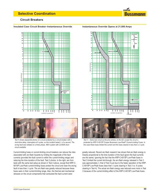
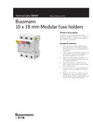
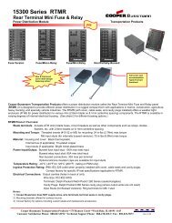
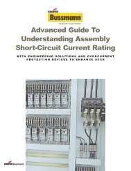
<strong>Selective</strong> <strong>Coordination</strong>Circuit BreakersInsulated Case Circuit Breaker–Instantaneous OverrideInstantaneous Override Opens at 21,000 Amps100080060040030010008006004003002000A200200100A10010080806040ICCB6040100A CB2000A ICCB30302020108643TIME IN SECONDS108643TIME IN SECONDS21.8.621.8.6.4.3.4.3.2.1.08.06InstantaneousOverride= 12X.2.1.08.06.04.03.04.03BLACKOUT!.02.02.0110020030040060080010002000300040006000800010,000CURRENT IN AMPERES20,00030,00040,00060,00080,000100,000.0110020030040060080010002000300040006000800010,000CURRENT IN AMPERES20,00030,00040,00021,000 AMPS60,00080,000100,000Test 4 shows sequential photos of a circuit protected by a circuit breaker with ashort-time delay: interrupted at 6 cycles, so this incident lasted 1 ⁄10 of a second. Thearcing fault was initiated on a three phase, 480V system with 22,600A shortcircuit available.Current-limiting fuses or current-limiting circuit breakers can reduce the risksassociated with arc-flash hazards by limiting the magnitude of the faultcurrents (provided the fault current is within the current-limiting range) andreducing the time duration of the fault. Test 3 photos, to the right, are fromtests with the same test setup as shown in Test 4 above, except that KRP-C-601SP Low-Peak current-limiting fuses protect the circuit and clear the arcingfault in less than 1 ⁄2 cycle. The arc-flash was greatly reduced because thesefuses were in their current-limiting range. Also, the thermal and mechanicalstresses on the circuit components that conducted the fault current wereTest 3 – Same test circuit as the prior photos, to the left, except the circuit isprotected by KRP-C-601SP <strong>Cooper</strong> <strong>Bussmann</strong> Low-Peak ® Current-Limiting Fuses. Inthis case these fuses limited the current and the fuses cleared in less than a 1 ⁄2 cycle.greatly reduced. Recent arc-flash research has shown that arc-flash energy islinearly proportional to the time duration of the fault (given the fault currentsare the same). Ignoring the fact that the KRP-C-601SP Low-Peak fuses inTest 3 limited the current let-through, the arc-flash energy released in Test 3was approximately 1 ⁄12 that of Test 4 just due to the faster operation of the KRP-C-601SP Low-Peak fuses (less than 1 ⁄2 cycle clearing in Test 3 vs. 6 cyclesclearing in Test 4). The actual arc-flash energy was reduced even more in Test3 because of the current-limiting effect of the KRP-C-601SP Low-Peak fuses.©2005 <strong>Cooper</strong> <strong>Bussmann</strong>99