Selective Coordination - Cooper Bussmann
Selective Coordination - Cooper Bussmann
Selective Coordination - Cooper Bussmann

You also want an ePaper? Increase the reach of your titles
YUMPU automatically turns print PDFs into web optimized ePapers that Google loves.
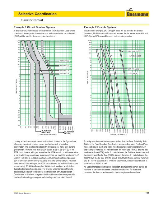
<strong>Selective</strong> <strong>Coordination</strong>Elevator CircuitExample 1 Circuit Breaker SystemIn this example, molded case circuit breakers (MCCB) will be used for thebranch and feeder protective devices and an insulated case circuit breaker(ICCB) will be used for the main protective device.1,000800600Example 2 Fusible SystemIn our second example, LPJ-(amp)SP fuses will be used for the branchprotection, LPS-RK-(amp)SP fuses will be used for the feeder protection, andKRP-C-(amp)SP fuses will be used for the main protection.1,000800600400300200400300200KRP-C-1600SP10080601600A ICCB1008060LPS-RK-400SPTIME IN SECONDS40302010864321.8.6.4.3400A MCCB200A MCCB100A MCCBTIME IN SECONDS40302010864321.8.6.4LPS-RK-200SPLPJ-100SP.2.3.2.1.08.06.04.03.1.08.06.04.02.03.01.021002003004006008001,0002,0003,0004,0006,0008,00010,000BLACKOUT(PARTIAL)CURRENT IN AMPERES20,00030,00040,00060,00080,000100,000BLACKOUT(TOTAL).011002003004006008001,0002,0003,0004,0006,0008,000CURRENT IN AMPERES10,00020,00030,00040,00060,00080,000100,000Looking at the time current curves for the circuit breaker in the figure above,where any two circuit breaker curves overlap is a lack of selectivecoordination. The overlap indicates both devices open. If any fault currentgreater than 750A and less than 3100A occurs at EL-1, EL-2 or EL-3, the200A circuit breaker will open as well as the 100A branch circuit breaker - thisis not a selectively coordinated system and does not meet the requirements of620.62. This lack of selective coordination could result in stranding passengersin elevators or not having elevators available for fire fighters. Fault currentsabove 3100A will open the 400A circuit breaker as well and faults aboveapproximately 16,000A will open the 1600A circuit breaker - which furtherillustrates the lack of coordination. For a better understanding of how toassess circuit breaker coordination, see the section on Circuit Breaker<strong>Coordination</strong> in this book. A system that is not in compliance may result inneedlessly stranding passengers and creating a serious safety hazard.To verify selective coordination, go no further than the Fuse Selectivity RatioGuide in the Fuse <strong>Selective</strong> <strong>Coordination</strong> section in this book. The Low-Peakfuses just require a 2:1 amp rating ratio to assure selective coordination. Inthis example, there is a 4:1 ratio between the main fuse (1600A) and the firstlevel feeder fuse (400A) and a 2:1 ratio between the first level feeder fuse andthe second level feeder fuse (200A). As well, there is a 2:1 ratio between thesecond level feeder fuse and the branch circuit fuse (100A). Since a minimumof a 2:1 ratio is satisfied at all levels for this system, selective coordination isachieved and 620.62 is met.As just demonstrated in the prior paragraph, the fuse time current curves donot have to be drawn to assess selective coordination. For illustrativepurposes, the time current curves for this example are shown above.©2005 <strong>Cooper</strong> <strong>Bussmann</strong>105