DCS 408 RELAISMODUL 100V - Udo Erpenstein GmbH
DCS 408 RELAISMODUL 100V - Udo Erpenstein GmbH
DCS 408 RELAISMODUL 100V - Udo Erpenstein GmbH
- No tags were found...

You also want an ePaper? Increase the reach of your titles
YUMPU automatically turns print PDFs into web optimized ePapers that Google loves.
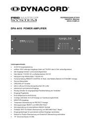
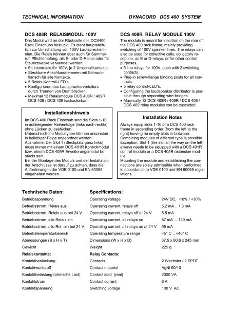
TECHNICAL INFORMATIONDYNACORD <strong>DCS</strong> 400 SYSTEM<strong>DCS</strong> <strong>408</strong>R <strong>RELAISMODUL</strong> <strong>100V</strong>Das Modul wird an der Rückseite des <strong>DCS</strong>400Rack Einschubs bestückt. Es dient hauptsächlichzur Umschaltung von <strong>100V</strong> Lautsprecherlinien.Die Relais können aber auch für Sammelruf,Pflichtempfang, als E- oder D-Relais oder fürSteuerzwecke verwendet werden.• 5 Linienrelais für <strong>100V</strong>, je 2 Umschaltkontakte.• Steckbare Anschlussklemmen mit Schraubflanschfür alle Kontakte.• 5 Relais-Kontroll-LED’s.• Konfigurieren des Lautsprecherverteilersdurch Trennen von Drahtbrücken.• Maximal 12 Relaismodule <strong>DCS</strong> <strong>408</strong>R / 409R<strong>DCS</strong> <strong>408</strong> / <strong>DCS</strong> 409 kaskadierbar.InstallationshinweisIm <strong>DCS</strong> 400 Rack Einschub sind die Slots 1-10in aufsteigender Reihenfolge (links nach rechts)ohne Lücken zu bestücken.Unterschiedliche Modultypen können ansonstenin beliebiger Folge angeordnet werden.Ausnahme: Der Slot 1 (Steckplatz ganz links)muss immer mit einem <strong>DCS</strong> 401R Kontrollmodulbzw. einem <strong>DCS</strong> 405R Erweiterungsmodul bestücktsein.Bei der Montage des Moduls und der Installationder Anschlüsse ist darauf zu achten, dass dieAnforderungen der VDE 0100 und EN 60065eingehalten werden.<strong>DCS</strong> <strong>408</strong>R RELAY MODULE <strong>100V</strong>The module is meant for insertion on the rear ofthe <strong>DCS</strong> 400 rack frame, mainly providingswitching of <strong>100V</strong> speaker lines. The relays canalso be used for collective calls, obligatory reception,as E or D-relays, or for other controlpurposes.• 5 line relays for <strong>100V</strong>, each with 2 switchingcontacts.• Plug-in screw-flange binding posts for all contacts.• 5 relay control-LED’s.• Configuring the loudspeaker distributor is possiblethrough separating wire-bridges.• Maximally 12 <strong>DCS</strong> <strong>408</strong>R / 409R / <strong>DCS</strong> <strong>408</strong> /<strong>DCS</strong> 409 relay modules can be cascaded.Installation NotesAlways equip slots 1-10 of a <strong>DCS</strong> 400 rackframe in ascending order (from the left to theright) leaving no empty slots in-between.Combining modules of different type is possible.Exception: Slot 1 (the slot all the way on the left)always needs to be equipped with a <strong>DCS</strong> 401Rcontrol module or a <strong>DCS</strong> 405R extension module.Mounting the module and establishing the connectionsare solely admissible when performedin accordance to VDE 0100 and EN 60065 regulations.Technische Daten:Specifications:Betriebsspannung Operating voltage 24V DC, -10% / +30%Betriebsstrom, Relais aus Operating current, relays off 5.2 mA .. 7.8 mABetriebsstrom, Relais aus bei 24 V Operating current, relays off at 24 V 5.5 mABetriebsstrom, alle Relais ein Operating current, all relays on 87 mA .. 130 mABetriebsstrom, alle Rel. ein bei 24 V Operating current, all relays on at 24 V 96 mABetriebstemperaturbereich Operating temperature range +5° C .. +40° CAbmessungen (B x H x T) Dimensions (W x H x D) 37.5 x 80.6 x 245 mmGewicht Weight 225 gRelaiskontakte:Relay Contacts:Kontaktbestückung Contacts 2 Wechsler / 2 SPDTKontaktwerkstoff Contact material AgNi 90/10Kontaktbelastung (ohmsche Last) Contact load (real) 2000 VAKontaktstrom Contact current 8 AKontaktspannung Switching voltage 100 V AC
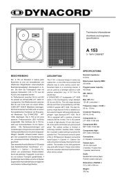
TECHNICAL INFORMATIONDYNACORD <strong>DCS</strong> 400 SYSTEM<strong>DCS</strong> <strong>408</strong>RRelay Module <strong>100V</strong>Rear PanelDATA4_ADATA3_ADATA3CLK2CLK2_ACLK3CLK3_A*RES+24VA1A3B18B16A2B17*RES_ARES_ABR3BR4BR2BR1A4EN 3_AEN 2_ADATA2_ADATA1CLK1_AP/SID+24VA6B21B19A5B20CN to BackplaneEN4EN4_AEN5EN5_AEN6EN6_AEN7EN7_A+24VBR7BR8BR6BR5A7A9B24B22A8B23EN8EN8_ABR11BR12BR10BR9A10A12RESB27EN 3+24VB25EN 2DATA2DATA1_ACLK1S/PRelayDriverA11B26+24VBR15 BR16 BR14 BR13A13A15DATA5DATA5_ADATA_SELDATA_SEL_AEN1EN1_AtDCDC+5V+24VB30B28A14B29Relay Module <strong>100V</strong><strong>DCS</strong> <strong>408</strong>RBLOCK DIAGRAMMON+MON-S1S2<strong>GmbH</strong> • Hirschberger Ring 45 • 94315 Straubing • Telefon (09421) 706-0 • Telefax (09421) 706-265Änderungen vorbehalten. Subject to be changed without prior notice. Printed in Germany 06. 10. 2001 357269