IGN 4-01-02.pdf - Water UK
IGN 4-01-02.pdf - Water UK
IGN 4-01-02.pdf - Water UK

You also want an ePaper? Increase the reach of your titles
YUMPU automatically turns print PDFs into web optimized ePapers that Google loves.
WATER INDUSTRYINFORMATION &GUIDANCE NOTE<strong>IGN</strong> 4-<strong>01</strong>-02July 1998: Issue 2(Page 1 of 11)ISSN 1353-2529Reprinted June 2006for web publicationTHE DETERMINATION OF END-LOADS FOR THEPERFORMANCE TESTING OF PIPELINE FITTINGSCONTENTS1. GENERAL SCOPE AND OBJECTIVES 12. DEFINITIONS 23. THEORETICAL CALCULATIONS 2(TYPE 2 FITTINGS)4. EXAMPLES OF THE USE OF THE 3EQUATIONS FOR DEFINING TESTFORCES FOR PIPE/FITTINGASSEMBLIES5. REFERENCES 8APPENDIX A - CALCULATED TEST 8FORCES FOR TYPE 1 AND TYPE 2MECHANICAL FITTINGS FOR USE WITHPE 80 PIPE MANUFACTURED TOWIS 4-32-03APPENDIX B - CALCULATED TEST FORCES 9FOR TYPE 1 AND TYPE 2 MECHANICALFITTINGS FOR USE WITH PE 100 PIPESMANUFACTURED TO WIS 4-32-13APPENDIX C - CALCULATED TEST 10FORCES FOR MECHANICAL FITTINGSFOR USE WITH PVC-U PIPE(TYPE 2 FITTINGS ONLY)APPENDIX D CALCULATED TEST 11FORCES FOR MECHANICAL FITTINGSFOR USE WITH DUCTILE IRON PIPE(TYPE 2 FITTINGS ONLY)1. GENERAL SCOPE ANDOBJECTIVESThis document is intended to provide a basis for theformulation of test criteria to assess the resistance ofmechanical fittings to end-loads, for below grounduse in water supply, distribution and service pipeapplications in the <strong>Water</strong> Industry. It does not includemethods of test but details methods to determine theend-loads imposed on fittings due to those operatingconditions which can be predicted. The pipe materialsto which the calculations can be applied are PE 80and PE 100 (of nominal size 20 to 1000), PVC-U (ofnominal size 90 to 630) and ductile iron (of nominalsize 100 to 1600).Examples of the application of the theory to PE 80 (toBS 6572/WIS 4-32-03), PE 100 (to WIS 4-32-13),PVC-U (to WIS 4-31-06) and ductile iron (to BS EN545) pipes and fittings have been included to illustratethe use of the equations.Appendices A, B, C and D contain examples ofsuitable forces for pull-out tests on PE 80, PE 100,PVC-U and ductile iron pipe/fitting assembliesrespectively, to act as a guide for the development oftest methods.It is intended that this document be used by thoseinvolved in the future preparation of specifications toensure that a consistent approach is adopted in thetesting of mechanical fittings for <strong>Water</strong> Industryapplications.This document is not intended to be used as aSpecification. Information contained within it is givenin good faith but neither <strong>UK</strong> <strong>Water</strong> Industry ResearchLtd., <strong>Water</strong> <strong>UK</strong> nor WRc plc can accept anyresponsibility for actions taken as a result.Technical enquiries to:WRc, Frankland Road, Blagrove, Swindon, Wilts, SN5 8YF Tel: (<strong>01</strong>793) 865151 E-mail: wisign@wrcplc.co.ukThis reprint has been prepared by the <strong>UK</strong> <strong>Water</strong> Industry and published by WRc plc. <strong>UK</strong> WIR ©1998
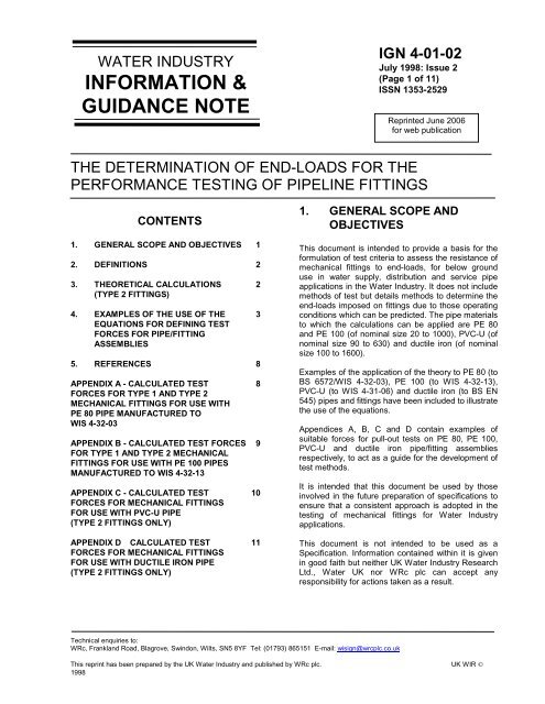
4. EXAMPLES OF THE USE OFTHE EQUATIONS FORDEFINING TEST FORCESFOR PIPE/FITTINGASSEMBLIESThe assessment of the end-load resistance ofmechanical fittings can be accomplished by means ofa pull-out test. The following procedures demonstratethe application of the theory given in clause 3 to thecalculation of pull-out forces for such performancetests.NOTE: This pull-out without pressure applicationrepresents the worst case. It is used because (a)end-load resistant fittings would be expected to holdeven when the system is depressurised and (b) it ismore practical to test in dry conditions.4.1 PE 80 pipe/fitting assemblies4.1.1 AssumptionsIn order to calculate the maximum end-loads exertedon a fitting due to the stresses in a pressurisedSDR 11 125mm PE 80 pipe, the followingassumptions are made:Maximum working pressure (P w ) = 10 barMaximum site test pressure (Ps) =1.5 x P w = 15 barMaximum temperaturevariation (∆T)= 40° CPoisson’s ratio (ν) = 0.42Young’s modulus (E at 20° C) = 593 MPaCoefficient of expansion (K) = 1.45 x 10 -4 ° C -1External diameter (D)= 125mmWall thickness (t)= 11.4mmInternal diameter (d)= 102.2mmYield stress (σ y ) (measured at = 15 MPaa strain rate of 125% min -1 and 23° C)NOTE 3: The strength properties of polyethylene arestrain-rate dependent. Where strain-rate dependentproperties have been used in the calculations, thetest forces must be applied at the equivalent strainrate.Testing at other strain-rates is permissibleprovided the test forces have been recalculated usingyield stress values appropriate to the chosen strainrate.Figure 2 can be used to define yield stressvalues for other extension rates between 1 and1000mm.min -1 .4.1.2 Calculations4.1.2.1 Type 1 fittingsTo comply with the definition given in clause 2, Type1 fittings for PE 80 pipes shall be capable ofwithstanding a force equivalent to that required tocause yield of a PE 80 pipe (i.e. fully end-loadresistant).For a pull-out test to assess the end-load resistanceof Type 1 fittings, the applied pull-out force, F y , istherefore required to be equivalent to that whichcauses yield in a PE 80 pipe, i.e.F y = σ y Awhere σ y = yield stressA = pipe wall cross-sectional areaThe test forces for nominal pipe sizes from 20 to1000 have been calculated using the appropriatepolyethylene pipe dimensions and assuming a yieldstress of 15 MPa (see 4.1.1). These are presented inTable A.1 of Appendix A.4.1.2.2 Type 2 fittingsTo comply with the definition given in clause 2, Type2 fittings shall be capable of withstanding themaximum axial forces assumed to be acting on thejoint under normal operating conditions. Thus, for theassessment of the end-load resistance, a Type 2fitting shall be considered to be subjected to a forceequivalent to that induced in a pipeline installed underconditions of maximum temperature change andoperated at its site test pressure. The followingdetails the calculations conducted to determine theappropriate test forces.NOTE 1: The maximum temperature variation hasbeen estimated from the maximum recorded <strong>UK</strong>summer temperatures and the minimum recorded <strong>UK</strong>ground temperatures (at pipe cover depth).NOTE 2: The Young’s modulus is defined as thatappropriate to the mean of the temperatures used inthese calculations (i.e. 20° C).(1) F L = pπD24=15 . x π x 1254= 18.41kN2from Equation (1)© 19984
<strong>IGN</strong> 4-<strong>01</strong>-02July 1998: Issue 2(Page 5 of 11)ISSN 1353-2529Figure 2 - The relationship between yield stress and extension rate for an MDPE pipe(2) F R = νp (D-t) A/2t from Equation (2)= 0.42 x 1.5 x ( 125 − 114 . ) x π8 x 114 .x (125 2 - 102.2 2 )= 12.77kNand(3) F T = ∆T.K.E.A. from Equation (3)= 40 x 1.45 x 10 -4 x 593= 13.99kN2 2x ( 125 − 102. 2 ) x π4(4) Unrestrained end-capsF max = F L = 18.41kNRestrained end-capsF max = F R + F T = 26.76kNSince F R + F T > F L , then F max is assumed to be26.76kN.F max represents the maximum longitudinal force on afitting joined to a predicted 10 bar rated, 125mmPE 80 pipe restrained at both ends and pressurisedto a test pressure of 15 bar.5© 1998
A Type 2 fitting is required to maintain resistance toend-loads at least equivalent to F max . For a pull-outtest to assess the end-load resistance, the appliedpull-out test force F should be that which can beinduced by F max plus a safety factor (25% has beenagreed for current purposes).NOTE: A margin of safety has already been includedin the calculations through the use of site testpressures and the maximum value of ∆T. Only asmall safety factor has therefore been added to allowresistance to be maintained during integrity testing ofthe pipeline.Using appropriate values of F max , test forces (F) canbe calculated for each remaining combination of pipesizes and classes. All test force values are presentedin Table A.2 of Appendix A.4.1.2.3 Type 3 fittingsThere are no requirements for pull-out resistance ofType 3 fittings.4.1.3 Assemblies incorporating polyethylene andother service pipe materialsWhere pipe/fitting assemblies incorporate bothpolyethylene and other service pipe materials, for thepurposes of end-load resistance assessment, theassembly is required to meet the performance criteriadefined by the polyethylene pipe material.4.2 PE 100 pipe/fitting assemblies4.2.1 AssumptionsIn order to calculate the maximum end-loads exertedon a fitting due to the stresses in a pressurisedSDR11 125mm PE 100 pipe (to WIS 4-32-13), thefollowing assumptions are made:Maximum working pressure (Pw) = 16 barMaximum site testing pressure (Ps) = 1.5 x P w= 24 barMaximum temperature variation (∆T) = 40° CPoissons ratio (ν) = 0.38Young’s modulus (E at 20° C) = 712 MPaCoefficient of expansion (K) =1.30x10 -4 C -1External diameter (D)= 125mmWall thickness (t)= 11.4mmInternal diameter (d)= 102.2mmYield stress (σ y ) (measured at astrain rate of 125% min -1 and 23° C)= 19 MPa(from WIS 4-32-13)NOTES 1, 2 and 3 from 4.1.1 apply.4.2.2 CalculationsTo comply with the definition given in clause 2, theapplied pull-out force, Fy (as given in 4.1.2.1) isrequired to be equivalent to that which causes yield ina PE 100 pipe.The test forces for pipe sizes from 90 to 1000 havebeen calculated using the appropriate PE 100dimensions and assuming a yield stress of 19MPa(see 4.2.1). These are presented in Table B1 ofAppendix B.4.2.2.2 Type 2 fittingsTo comply with the definition given in clause 2, Type2 fittings shall be capable of withstanding themaximum axial forces assumed to be acting on thejoint under normal operating conditions. Thus, forassessment of the end-load resistance, a Type 2fitting shall be considered to be subject to a forceequivalent to that induced in a pipeline installed underconditions of maximum temperature change andoperated at its site test pressure. The followingdetails the calculations conducted to determine theappropriate test forces.(1) F L = pπD24= 2 . 4 x π x 1254= 29.452 kN2from Equation (1)(2) F R = νp (D-t)A/2t from Equation (2)= 0.38 x 2.4 x ( 125 − 114 . ) xπ8 x114.F R = 18.487 kN(3) F T = ∆T.K.E.Ax (125 2 - 102.2 2 )= 40 x 1.3 x 10 -4 x 712 x ( 125 − 102. 2 ) x π4= 15.063 kN(4) Unrestrained end-capsF max = F L = 29452 N2 2© 19986
<strong>IGN</strong> 4-<strong>01</strong>-02July 1998: Issue 2(Page 7 of 11)ISSN 1353-2529Restrained end-capsF max = F R + F T = 18487 + 15063= 33550NSince F R + F T > F L then F max is assumed to be33.6kN.F max represents the maximum longitudinal force on afitting joined to a predicted 16 bar rated, 125mmPE 100 pipe restrained at both ends and pressurisedto a test pressure of 24 bar.A Type 2 fitting is required to maintain resistance toend-loads at least equivalent to F max . For a pull-outtest to assess the end-load resistance, the appliedpull-out test force F should be that which can beinduced by F max plus a safety factor (25% has beenagreed for current purposes).NOTE: A margin of safety has already been includedin the calculations through the use of site testpressures and the maximum value of ∆T. Only asmall safety factor has therefore been added to allowresistance to be maintained during integrity testing ofthe pipeline.Using appropriate values of F max , test forces (F) canbe calculated for each remaining combination of pipesizes and classes. All test force values are presentedin Table B2 of Appendix B.4.3 PVC-U pipe/fitting assemblies4.3.1 AssumptionsIn order to calculate the maximum end-loads exertedon a fitting due to the stresses in a pressurised 12.5bar rated, 110mm PVC-U pipe, the followingassumptions are made:Maximum working pressure (Pw) = 12.5 barMaximum test pressure (Ps)= 1.5 x Pw= 18.75 barMaximum temperature variation (∆T) = 40° CPoissons ratio (ν) = 0.38Young’s modulus (E)= 3.4 GPaCoefficient of expansion (K) = 6 x 10 -5 C -1External diameter (D)= 110.0 to110.4mmWall thickness (t)= 5.3mmInternal diameter (d)= 99.4 to99.8mm4.3.2 CalculationsType 1 fittings are not currently made for use withPVC-U pipes. For Type 2 fittings the calculationsdetailed in 4.1.2.2 for polyethylene pipe can besimilarly conducted for PVC-U using the assumptionsgiven in 4.3.1.(1) F L = 1875 .2x ( 110. 2) x π = 17.88kN4(2) F R = 1.875 x ( 110 . 2 − 5 . 3 ) x 0 . 388 x 5.3x (110.2 2 - 99.6 2 ) x π = 12.32kN(3) F T = 40 x 6 x 10 -5 x 3400 x (110.2 2 - 99.6 2 )x π = 14.25kN(4) Unrestrained end-capsF max = F L = 17.88kNRestrained end-capsF max = F R + F T = 26.57kNSince F R + F T > F L , then F max is assumed to be26.57kN.F max represents the predicted maximum longitudinalforce on a fitting joined to a 12.5 bar rated, 110mmPVC-U pipe restrained at both ends and pressurisedto a test pressure of 18.75 bar. To this maximumforce, a safety factor of 25% is added to calculate thepull-out test force, F, for a Type 2 fitting for this sizeand class of PVC-U pipe.Using appropriate values of F max , test forces (F) canbe calculated for each remaining combination of pipesizes and classes. All test force values are presentedin Table B.1 of Appendix B.4.4 Ductile iron pipe/fitting assemblies4.4.1 AssumptionsIn order to calculate the maximum end-loads exertedon a fitting due to the stresses in a pressurised100mm, Class K9 ductile iron pipe, the followingassumptions are made:Maximum working pressure (Pw)Maximum test pressure (Ps)Maximum temperature variation (∆T)= 16 bar= 1.5 x Pw= 24 bar= 40° C7© 1998
Poissons ratio (ν) = 0.26 - 0.29Young’s modulus (E)= 169 GPaCoefficient of expansion (K) = 10.5 - 11.8x 10 -6 C -1External diameter (D)= 118mmWall thickness (t)= 6.1mmInternal diameter (d)= 105.8mm4.4.2 CalculationsType 1 fittings requirements are not applicable toductile iron pipes.For the assessment of the end-load resistance ofType 2 fittings for DN 100, Class K9 ductile iron pipe,F max can be calculated as follows:2 x(1) F L = 2.4 x ( 118) π = 26.25kN4(2) F R = 2.4 x ( 118 − 61 . ) x 0 . 278 x 61 .x (118 2 - 105.8 2 ) x π = 12.75kN(3) Due to the relative rate of heat transfer in aductile iron pipe for a given wall thickness (coefficientof heat transfer k is 48, 0.5 and 0.15W/m/K for castiron, HDPE and PVC respectively), it has beenassumed that any contraction due to temperaturevariation will occur during installation, such that thetemperature change after assembly will be negligible.In particular for a temperature change ∆T of less than22° C after installation, F R + F T < F L .F max is assumed to be 26.25kN.F max represents the maximum predicted longitudinalforce on a fitting joined to a DN 100, Class K9 ductileiron pipe pressurised to a test pressure of 24 bar. Tothis maximum force, a safety factor of 25% is addedto calculate the pull-out test force, F, for a Type 2fitting for this size and class of ductile iron pipe.Using appropriate values of F max , test forces (F) canbe calculated for each remaining pipe size. All testforce values are presented in Table D.1 ofAppendix D.This <strong>IGN</strong> refers to:BS EN 545 Ductile iron pipes, fittings,accessories and their joints forwater pipelines - Requirements andtest methods.BS 6572WIS 4-31-06WIS 4-32-03Specification for blue polyethylenepipes up to nominal size 63 forbelow ground use for potable water.<strong>Water</strong> Industry Specification for blueunplasticised PVC (PVC-U)pressure pipes and fittings for buriedcold potable water - Metric series.<strong>Water</strong> Industry Specification for bluepolyethylene (PE) pressure pipe forcold potable water (nominal size 90to 1000) for underground orprotected use.WIS 4-32-13 Specification for blue higherperformance polyethylene,HPPE/PE 100, pressure pipes,nominal size 90 to 1000, forunderground or protected use forthe conveyance of water intendedfor human consumption.APPENDIX A - CALCULATED TESTFORCES FOR TYPE 1 AND TYPE 2MECHANICAL FITTINGS FOR USEWITH PE80 PIPE MANUFACTUREDTO WIS 4-32-03A.1 Type 1 FittingsTable A.1 presents the pull-out test forces for PE80pipe/Type 1 fitting assemblies of nominal sizes overthe range 20 to 1000. The properties listed in 4.1.1are assumed to apply with the relevant pipedimensions.NOTE: For PE80 pipes whose parameters vary fromthese assumed values, the criteria in Table A.1 willneed to be re-calculated using the appropriatefigures.5. REFERENCESTable A.1 - Pull-out test forces for Type 1 fittingsfor use with PE80 pipeNomTest force Fy (kN)Size SDR SDR SDR SDR SDR© 19988
<strong>IGN</strong> 4-<strong>01</strong>-02July 1998: Issue 2(Page 9 of 11)ISSN 1353-252911 17 17.6 26 3320 225 332 450 1063 1590 32 21 2<strong>01</strong>10 47 32 31125 61 41 39160 100 67 65 45180 126 85 82 56225 198 132 128 88250 243 163 158 109280 305 205 198 136315 386 259 251 173355 491 329 317 219 177400 624 417 404 277 225450 790 528 512 351 284500 975 652 629 433 349560 1219 818 789 543 440630 1544 1035 1000 688 555710 1315 1269 875 707800 1670 1611 1109 895900 2113 2037 1411 11351000 2609 2516 1740 1398Strain rate = 125% min -1 at 23° CA.2 Type 2 FittingsTable A.2 presents the pull-out test forces for PE80pipe/Type 2 fittings assemblies of nominal sizes overthe range 20 to 1000. The properties listed in 4.1.1are assumed to apply with the relevant pipedimensions and site test pressures.NOTE: For PE80 pipe whose parameters vary fromthese assumed values, the criteria in Table A.2 willneed to be re-calculated with the appropriate figures.90 14 12 12110 21 18 18125 27 23 23160 44 38 37 34180 55 48 47 43225 87 75 74 66250 107 92 91 82280 134 116 114 103315 170 146 145 130355 216 186 184 166 158400 274 236 233 210 200450 347 299 296 266 253500 428 369 364 328 313560 536 463 457 412 392630 679 585 579 521 496710 744 735 662 631800 944 933 840 800900 1195 1181 1065 1<strong>01</strong>31000 1475 1458 1314 1251Strain rate = 125% min -1 at 23° CAPPENDIX B - CALCULATED TESTFORCES FOR TYPE 1 AND TYPE 2MECHANICAL FITTINGS FOR USEWITH PE100 PIPESMANUFACTURED TO WIS 4-32-13B.1 Type 1 FittingsTable B.1 presents the pull-out test forces for PE100pipe/Type 1 fitting assemblies of nominal sizes overthe range 90 to 1000. The properties listed in 4.2.1are assumed to apply with the relevant pipedimensions.NOTE: For PE100 pipes whose parameters vary fromthese assumed values, the criteria in Table B.2 willneed to be re-calculated using the appropriatefigures.Table A.2 - Pull-out test forces for Type 2 fittingsfor us with PE80 pipeTable B.1 - Pull-out test forces for Type 1 fittingsfor use with PE100 pipeNomSizeSDR11Test force F (kN)SDR17.6SDR17SDR26SDR33NomTest force F (kN)Size SDR11SDR17SDR17.6SDR2690 40 27 26SDR339© 1998
110 60 40 39125 77 52 5<strong>01</strong>60 127 85 82 57180 160 107 103 71225 250 167 162 111250 308 207 200 138280 386 259 251 172315 489 328 317 219355 622 416 402 277 224400 790 529 511 351 285450 10<strong>01</strong> 669 649 444 359500 1234 826 797 548 443560 1544 1036 1000 688 557630 1956 1312 1266 872 704710 1666 1607 1109 896800 2115 2041 1405 1134900 2677 2580 1787 14371000 3305 3187 2204 1771Strain rate = 125% min -1 at 23° CB.2 Type 2 FittingsTable B.2 presents the pull-out test forces for PE100pipe/Type 2 fittings assemblies of nominal sizes overthe range 90 to 1000. The properties listed in 4.2.1are assumed to apply with the relevant pipedimensions and site test pressures.NOTE: For PE100 pipe whose parameters vary fromthese assumed values, the criteria in Table B.2 willneed to be re-calculated with the appropriate figures.160 55 49 49 45180 70 62 61 57225 109 97 96 89250 134 120 119 110280 168 150 149 137315 213 190 188 174355 270 241 239 221 213400 343 306 303 280 271450 435 387 384 355 343500 536 478 474 438 423560 672 600 594 550 531630 851 759 753 696 671710 964 956 884 853800 1224 1213 1122 1082900 1549 1535 1421 137<strong>01</strong>000 1913 1896 1754 1691Strain rate = 125% min -1 at 23° CAPPENDIX C - CALCULATED TESTFORCES FOR MECHANICALFITTINGS FOR USE WITH PVC-UPIPE (TYPE 2 FITTINGS ONLY)Table C.1 presents the pull-out test forces for PVC-Upipe/Type 2 fitting assemblies of nominal sizes overthe range 90 to 630. The properties listed in 4.2.1 areassumed to apply with the relevant pipe dimensionsand site test pressures.Table C.1 - Pull-out test forces for Type 2 fittingsfor use with PVC-U pipeNominalsizeTest force F (kN<strong>01</strong>2.5 bar ratedpipe90 22 15110 33 22160 70 46200 109 72250 170 112315 270 178400 436 287450 552 363500 681 448630 1080 7118 bar ratedpipeTable B.2 - Pull-out test forces for Type 2 fittingsfor us with PE100 pipeNomSizeTest force F (kN)SDR SDR17 17.6SDR1190 17 15 15110 26 23 23125 34 30 30SDR26SDR33NOTE: For PVC-U pipes whose parameters varyfrom these assumed values, the criteria in Table C.1will need to be re-calculated using the appropriatefigures.APPENDIX D - CALCULATED TESTFORCES FOR MECHANICALFITTINGS FOR USE WITH DUCTILE© 199810
<strong>IGN</strong> 4-<strong>01</strong>-02July 1998: Issue 2(Page 11 of 11)ISSN 1353-2529IRON PIPE (TYPE 2 FITTINGSONLY)Table D.1 presents the pull-out test forces for ductileiron pipe/Type 2 fitting assemblies of nominal sizesover the range 100 to 1600. The properties listed in4.4.1 are assumed to apply with the relevant pipedimensions and site test pressures.NOTE: For ductile iron pipes whose parameters varyfrom these assumed values, the criteria in Table D.1will need to be re-calculated using the appropriatefigures.Table D.1 - Pull-out test forces for Type 2 fittingsfor use with ductile iron pipeNominal sizeTest force F (kN)100 33150 68200 116250 177300 250350 337400 434450 543500 667600 950700 1283800 1670900 21041000 25881100 31271200 37111400 50361600 655511© 1998
![Corporate social responsibility [CSR] has different ... - Water UK](https://img.yumpu.com/51398482/1/184x260/corporate-social-responsibility-csr-has-different-water-uk.jpg?quality=85)