IGN 4-37-02.pdf - Water UK
IGN 4-37-02.pdf - Water UK
IGN 4-37-02.pdf - Water UK

You also want an ePaper? Increase the reach of your titles
YUMPU automatically turns print PDFs into web optimized ePapers that Google loves.
WATER INDUSTRYINFORMATION &GUIDANCE NOTE<strong>IGN</strong> 4-<strong>37</strong>-02March 1999: Issue 1(Page 1 of 12)ISSN 1353-2529Reprinted June 2006for web publication<strong>UK</strong> <strong>Water</strong> IndustryDES<strong>IGN</strong> AGAINST SURGE AND FATIGUE CONDITIONS FORTHERMOPLASTIC PIPESFOREWORDPast advice on dealing with transient pressuresin plastic pipelines given in the PipelineMaterials Selection Manual (PMSM) issued forthe <strong>Water</strong> Industry in 1995 by WSA, has beenrecognised as being extremely conservative.New experimental data obtained for <strong>UK</strong>WIR(ref. 1) now make it possible to establish morerealistic rating criteria to cope with 'surge andfatigue' conditions for the full range ofthermoplastic pipe materials that are currentlyused by the <strong>Water</strong> Industry.This Information and Guidance Note, whichoffers new advice, has been prepared by thePipeline Innovation Group of <strong>UK</strong>WIR acting onbehalf of the <strong>Water</strong> Mains and Services andEngineering and Operations Committees of the<strong>UK</strong> <strong>Water</strong> Industry.This document is not intended to be used as aspecification. Information contained within it isgiven in good faith but neither <strong>UK</strong> <strong>Water</strong>Industry Research Ltd, <strong>Water</strong> <strong>UK</strong> not WRc plccan accept any responsibility for actions takenas a result.It has been found that high toughnessPolyethylene materials may be considered notto need any de-rating to cope with repeatedcycling, but they must still be designed to resistover-pressurisation and collapse. Hence, adviceis given here to cope with Surge and Fatigue asseparate phenomena. This is consistent with theCEN approach expressed in the <strong>Water</strong> SystemStandard prEN805 which requires suppliers toquote a maximum pressure (PMA) inclusive ofsurge which can be tolerated by any pipe.It is not possible to give absolute design criteria,which will apply to each and every pipeconstruction scheme. When new pumpingmains are to be designed it is strongly advisedthat a separate hydraulic analysis be conductedto assess the magnitude and frequency ofsurges from pumps and valves which are to beused. The design advice offered in this <strong>IGN</strong> canbe used to assist in the choice of pipe wallthickness that is needed for any plastic pipesthat may be considered.However, it is also recognised that much of the<strong>UK</strong> capital expenditure on pipes is for thereplacement and rehabilitation of the existingnetwork. It may not be possible or practicable tocarry out a surge analysis in such cases.Therefore, outline design advice is offered tocover those situations where presentoperational experience suggests that there areno unusual surge and fatigue problems fromexisting pumps and valves. For these cases, it isgenerally assumed that the peak pressure willbe no more than twice the steady statecondition. The frequency with which suchsurges occur is a matter for local judgment.The scope of the guidance is generally limited toonly those materials which meet therequirements of BS3505 (PVC-U), WIS 4-31-08(MOPVC), WISs 4-32-03/09 (PE80 water andsewer pipes), WIS 4-32-13 (PE100 pipes) andthe BSI PAS 27 Specification for modified PVC-A pipes. GRP pipes are not covered by this <strong>IGN</strong>.Technical enquiries to:WRc, Frankland Road, Blagrove, Swindon, Wilts, SN5 8YF Tel: (01793) 865151 E-mail: wisign@wrcplc.co.ukThis reprint has been prepared by the <strong>UK</strong> <strong>Water</strong> Industry and published by WRc plc. <strong>UK</strong> WIR ©1999
Any pipe or ancillary equipment (e.g. valves,fittings and services) made from materials NOTincluded above (including anchoring devices,thrust blocks and clamps) must be designed toresist the expected peak pressures in thesystem, as per the recommendations given inthe Pipeline Materials Selection Manual.CONTENTSFOREWORDA. BACKGROUNDA.1 GeneralA.2 Historical Design for Surge andFatigueA.3 Definitions – Surge and FatigueB. DES<strong>IGN</strong> FOR SURGE & FATIGUEB.1 Surge DesignB.2 Pressure Ratings to Resist SurgeB.3 Example of Use of Surge FactorsB.4 Resistance to BucklingB.5 Design for Fatigue of ThermoplasticsPipesC. REFERENCESSECTION A: BACKGROUNDA.1 GeneralFor many years, it has been the policy of the <strong>UK</strong><strong>Water</strong> Industry to recommend that PVC-U andPE pipes be derated where mains are expectedto be subject to repeated surge pressures. Thedesign advice outlined in BS CP312 for PVC-Uhas been incorporated in the 1995 edition of thePMSM.New research on the behaviour of hightoughness PVC and PE pressure pipesconducted for the <strong>UK</strong> <strong>Water</strong> Industry by <strong>UK</strong>WIRhas shown that changes should be made to therecommendations. Surge alone is notconsidered to be a major cause of problemsexperienced in service and it has beendetermined that the new high toughness PEmaterials are apparently not affected byrepeated cyclic loading.The British Plastics Federation have beenconsulted on the contents of this <strong>IGN</strong> as have all<strong>UK</strong> consultants and academics who havehistorically been involved with the fatigue testingof plastics. They have all expressed theirapproval of the new initiative.A.2 Historical Design for Surge and FatigueIn all plastic pipe specifications, suppliers arerequired to generate long term design data bytesting pipes at different static pressures untilthey burst. The design basis requires that thestress predicted to result in failure at 50 years isdetermined. The Design Stress is established byapplication of a factor of safety and the DesignPressures are derived for pipes of various wallthicknesses.In spite of the use of large safety factors andextensive long-term static pressure testing,there have been historic failures of PVC-U pipemanufactured in the 1960/70s. Such failureswere initially assumed to have been caused byrepeated over-pressurisation by surge (ref. 1).Subsequently a number of researchprogrammes have shown that repeated loadcycling will cause an accelerated decay in thestrength characteristics of PVC-U (e.g. refs. 2 to6). Hence, to guard against cyclic pressure© 1999 2
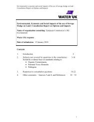
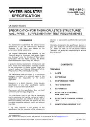
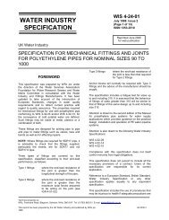
<strong>IGN</strong> 4-<strong>37</strong>-02March 1999: Issue 1(Page 3 of 12)ISSN 1353-2529failures in PVC-U pipes, BS CP312 wasamended in 1977 (ref. 7) to limit the maximumstress level, which could be applied.CP312 recommends that the maximumpressure amplitude of a surge event shouldalways be less than half the static pressurerating of the pipe. In some pumping situations,the pressure variation can be twice the staticpressure rating and thus pipe thickness wouldneed to be quadrupled to protect against thepressure excursions. In pipe design manualsproduced by WRc on behalf of the <strong>Water</strong>Industry, BS CP312 criteria have been adoptedand applied to PVC-U. However, althoughCP312 strictly only applied to PVC-U pipes, thecriteria have also been extended to include PEpipes in the PMSM. This has led to more limiteduse of plastics pipes for pumped mains and tosignificantly increased costs where plastics havebeen specified.There is compelling evidence to suggest thatthe prime cause of poor PVC-U performancewas poor resistance to static overloading frombending stresses generated locally by pointloads. When new <strong>Water</strong> Industry and BritishStandards were introduced requiring suppliersto increase the fracture toughness of PVC-Upipes, the failure rates of pipes decreased.<strong>Water</strong> Company burst records show that PVC-Upipe made to the high toughness criteria into <strong>UK</strong>Specifications in 1986 (and adopted by BritishStandards in BS3505) have performedsatisfactorily.There have been few reported failures of anyhigh toughness PVC, MOPVC or PE pipes dueto surge or fatigue conditions.A. 3 Definitions - Surge and FatigueA.3.1 Effects of Surge and Fatigue'Surge and Fatigue’ are often combined as acollective term. However although bothphenomena arise from the same events (valvesclosing quickly, pump shut down etc.) theyshould be considered separately since theydescribe different effects on the pipe material.Surge generates pressures generally rising inexcess of the static rating with the pressurebeing applied in very short timescales.Fatigue is associated with cyclic pressurevariation that is applied on a repeated basisover a long term. It is a condition often occurringbelow the rated pressure.In a pumped system, the most frequent eventsthat cause unsteady variations in pressure arepump start-up/shutdown. Secondary eventssuch as air and line valves opening and closingcould also generate pressure excursions.Generally, it is the fast closing of valves anduncontrolled pump shutdowns that cause themost severe changes and oscillations inpressure (ref. 8).It should be noted that the stiffnesses of plasticpipes are lower than for metal/AC pipes andthus the pressure shock wave transmissionspeeds are lower. Consequently, the pressurerise rates and peak levels will be much reduced.It is thus important that designers who areconducting hydraulic simulations use the correctshort-term modulus for each material (as givenin Table 1), so that realistic results are obtained.A.3.2 Defining SurgeSurge creates fluctuations in pressure about thesteady state level. The initial rate of pressurechange is very high but of short duration. Thefluctuations decay rapidly. An extreme pressurefluctuation trace caused by the instantaneousclosing of a solenoid valve on a 25mm PE pipeis shown in figure 1. For larger distribution andbranch mains, the rise rates will be lower butnevertheless, the peak pressure may beconsiderably in excess of the steady state case,and the minimum value may be subatmospheric.Extremes of both high and lowpressure may cause damage. High-pressurepeaks may cause pipe rupture.3© 1999
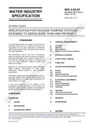
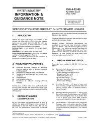
8P ressu re(b a r)765M a x P ressu reP ressu reR an g e43S te a d y S ta te P re ssu re210M in P re ssu re0 1 2 3 4 5 6 7T im e (s)Figure 1: Typical Pressure Fluctuation from Sudden Valve Closure in a PE SDR11 PipeIf sub-atmospheric troughs occur, these maycause wall collapse by buckling and for asystem joined by sockets and spigots there maybe permanent problems with sealing ringdisplacements.Problems with very low pressures will be lesssevere in a welded PE system since localiseddeformation caused by an extreme subatmosphericsurge will be recovered when thepressure is restored.In both cases however, designers need to avoiddifficulties by designing the wall section to givethe pipe sufficient reserves of strength andstiffness to operate without fear of failure byover-pressure or collapse by buckling.A.3.3 Response of Thermoplastics to HighRate LoadingThermoplastics such as PVC and PE respond tohigh rates of loading by exhibiting greaterstrength and stiffness, since the materials’entangled molecular chain structure providesresistance to deformation. Hence, at highpressurisation rates pipes are better able toresist the higher stress levels generated bysurge. Also, the strength of both materials willincrease with high rates of loading.Independent tests for <strong>UK</strong>WIR have been madeon various pre-notched (10% of wall) PVC andPE pipes where the pressure was raised atdifferent rates until failure occurred. The dataare shown in figure 2 where pressures at failurefor PVC and PE pipes are shown to increase asa function of loading rate.Clearly, if a large crack has been growing due tolong term static overloading (e.g. via pointloading of a pipe resting on a boulder), then anysurge may cause failure to occur prematurely.This often happened with low toughness PVC-U.© 1999 4
<strong>IGN</strong> 4-<strong>37</strong>-02March 1999: Issue 1(Page 5 of 12)ISSN 1353-2529807060504030Pressureat Burst(bar)PE100 1PE100 2MoPVCPVCuMDPE PE8020Pressure Rate (bar/sec)100.00 0.01 0.10 1.00 10.00 100.00PVC-AFigure 2: Effect of Pressure Rise Rate on Strength of Plastics Pipes with 10% External DefectsA.3.4 Defining FatigueFatigue is often associated with repeatedpressure variations about a mean value. Thedifference between the maximum and minimumpressures is defined as the 'range' (see figure1). It is the cyclic loading condition that hascaused brittle crack initiation and prematurecrack growth at low stress levels in metals inmany applications.This is not a problem with the slow diurnalpressure cycles which frequently occur indistribution systems, but in circumstances whereshort term surges may be repeated at frequentintervals, there is concern that there may be aweakening of pipes due to fatigue.From experimental studies, it is commonlyaccepted that it is the total pressure range,which determines the decrease in lifetime infatigue. Therefore, before considering choice ofthe appropriate pipe rating, the designer shouldknow the maximum and minimum pressures,which are to be expected in a surge event. Thismay be determined by carrying out a formalsurge analysis.Designers of discrete pumped mains arerecommended to conduct studies to determineexpected pressure excursions – using moduliand stiffnesses relevant to the materialconcerned.A.3.5 Materials Behaviour : Cyclic Loadinga) PVC MaterialsMany historical research programmes haveshown that:5© 1999
100StressRange(MPa)10PVC-A 10 O CExpected Static Decay PVC-UMOPVC1No of CyclesPVC-U& PVC-Aat 20 o C1.E+02 1.E+03 1.E+04 1.E+05 1.E+06 1.E+07 1.E+08Figure 3: Regression of Strength of PVC Materials under Cyclic Loading• the long term properties of PVC-U andthose with added impact modifiers (PVC-A)are reduced significantly by repeated cyclicloading.• The presence of notches, scores and otherdefects in the pipe walls will further reducethe overall pipe lifetime.• Different types of PVC-U and PVC-A havesimilar cyclic loading resistance. Adding themodifier does not increase resistance tocyclic loading.• Increasing the static toughness of PVC-Ualso has no effect on improving the fatiguelifetime.• Introducing molecular orientation into PVCpipe walls has been found to give significantimprovements to the resistance to failurefrom cyclic loading.b) PE MaterialsFor PE pipes, there is no reported history ofservice problems caused by long term failuredue to fatigue. Moreover, research studies haveshown that the fatigue resistance properties ofvarious PE types can be significantly different.The experimental data generated as part of the<strong>UK</strong>WIR programme (ref. 1) show that PE80 andPE100 materials which have satisfied the stresscrack resistance requirements in current <strong>Water</strong>Industry Specifications do not have significantreductions in lifetimes under cyclic loading.There is thus no need to de-rate their staticpressure rating to account for fatigue. This is asignificant change to the advice in the PMSM.However, other test data reported in theliterature do indicate that PE materials with lowlong term static stress crack resistance belowthe requirements of WIS specifications can bemade to fail prematurely under cyclic loading(see figure 4). As with PVCs, there is a need tode-rate (as recommended in the PMSM) forthese types of PE.A.3.6 Effect of TemperatureA recent study (ref. 10) has shown that alteringthe test/service temperature can significantlyalter the lifetime of PVC-A pipes (see figure 5).Reducing temperature from 30°C to 5°C givesan order of magnitude increase in lifetime. PVC-U lifetimes are changed in the same way, but toa significantly lower degree.© 1999 6
<strong>IGN</strong> 4-<strong>37</strong>-02March 1999: Issue 1(Page 7 of 12)ISSN 1353-2529100StressRange(MPa)PE100meeting WIS criteria10HDPE with poor staticcrack grow th resistance1No of Cycles to failure1.E+01 1.E+02 1.E+03 1.E+04 1.E+05 1.E+06 1.E+07 1.E+08Figure 4: Regression of Strength of PE Materials under Cyclic Loading1,000,000Cyclesto failure100,000PVC-APVC-A 95PVC-A 9610,000PVC-UPVC-A 971,000Temperature (C)0 10 20 30 40PVC-UFigure 5: Effect of Temperature on Cycles to Failure of Pre-Notched Samples ofPVC-U and PVC-A PN10 pipes pressurised between 2-8 bar range (ref. 10)7© 1999
B. DES<strong>IGN</strong> FOR SURGE AND FATIGUEB.1 Surge DesignDuring routine operation of a water pipe system,there are random, isolated events wherepressures may surge to high levels withoutcausing fatigue problems (e.g. emergency pumpshut downs). It is necessary to specify theallowable pressure limits for each material toresist these peak surge events. A value formaximum pressure resistance including surge(PMA) will be an EN requirement when prEN805is ratified.It is also necessary to consider the effects ofsingle surges on buckling resistance when theminimum pressure drops to sub-atmosphericlevels.B.2 Pressure Ratings to Resist SurgeIt is the responsibility of the system designer tochoose whether to conduct a formal surgeanalysis. For all rising mains, trunk mains andspecial pump/valve circumstances a detailedsurge analysis should be conducted. For theidentification of the peak surge, the worstanticipated event (e.g. emergency trip of allpumps) should be considered.inspection of historical designs and fieldmeasurements by Hydraulic Analysis Ltd., it hasbeen determined that for PE pipes in distributionsystems, no surge event showed rise rates ofmore than 8 bar/sec.The evidence from testing (figure 2) shows thatstandard thermoplastics used by the <strong>UK</strong> <strong>Water</strong>Industry will sustain pressures in excess of twicetheir static ratings at such high rates of pressurerise.To determine the allowable pressure resistanceof thermoplastic pipes, it is possible to use datarelating pressure resistance to the rate ofpressure rise (figure 2) to compute 'surgefactors'.Multiplying the pipe rating by the factors gives agood indication of the maximum pressure whichcan be sustained at any given pressure riserate.Note: The peak failure pressures in tests at allrise rates have been divided by a safety factorof 1.5 and then by the pressure rating toproduce figure 6.As part of a joint <strong>Water</strong> Industry and BPFresearch programme (ref. 8) and from detailed3.53.0SurgeFactorSurge Factors for Notched Plastics PipesPE80MoPVC/PVC-U2.5PE1002.0PVC-A1.51.0Surge Factor=Peak Pressure/(1.5*Rating)0.1 1.0 10.0 100.0Pressurisation Rate (bar/sec)Figure 6: Surge Factors for a Range of Thermoplastics Pressure Pipes at 20 o C© 1999 8
<strong>IGN</strong> 4-<strong>37</strong>-02March 1999: Issue 1(Page 9 of 12)ISSN 1353-2529B.3 Example of Use of Surge FactorsSuppose the hydraulic analysis of a schemeindicated that:• The steady state pressure was determinedto be 6 bar.• The pressure rise rate for the worst case'event' was calculated to be 4 bar/sec andthe peak pressure was predicted to be12 bar.• From figure 6, the surge factor for PE 100 at4 bar/sec would be 2.5. Therefore a piperated at 6 bar (PN6) for static pressurewould be capable of resisting a peak surgepressure of 15 bar (6*2.5). This would besecure.Note: if the designer opts to increase the wallsection to gain a greater safety factor, then thesurge analysis should be repeated since thesurge calculation itself is dependant on the SDRwhich is used. Stiffer pipes will cause higherwave speeds and peak values to be generated.B.4 Resistance to BucklingWhere a surge 'event' creates a subatmospheric pressure, the design shouldconsider resistance to collapse. Thebackfill/native soil stiffnesses dominate allunderground deformations of a flexible pipe andthe new <strong>UK</strong> design procedure in the annex toEN1295 gives the appropriate formulae forcalculating the safety factors for bucklingresistance.Where there are doubts about the potential siteconditions, designers should carry out a detailedanalysis both of the ground conditions as well asprojected operational loadings.The modulus of the native soil needs to beestimated and the type of in-fill and itscompaction need to be specified to ensureadequate support to the pipe. Because pipeinstallations may be made in widely different soiltypes and using different in-fill materials, it isonly appropriate to give general guidance forvacuum collapse for worst case burialconditions.Using short term modulus values given in Table1, specimen results are given for a range ofdifferent pipes and pressure classes whereextreme conditions are assumed for pipesoperating in conventional distribution systems.It can be seen that for an assumption of pipewith typical ovality (10% for coiled PE, 5% forPVCs) there are adequate safety factors for afull vacuum generated by the surge 'event'. Thisshould give confidence that buckling is not aproblem for well installed pipes, since thecalculations here assume poor ground andbarely adequate backfill properties.Where PE pipes are installed by slip lining anexisting pipe or bursting out an old iron mainsuch that there is no soil surround, calculationsshow that all pipes with ratings of SDR 26 orlower, retain safety factors of at least 2.E (MPa) PN16 PN12.5 PN10 PN8 PN6HPPE 1700 3.4 2.1 1.7 1.4MDPE 1400 3.2 2.0PVC-A 3300 3.1 2.5 2.0 1.8PVC-U 3500 3.6 2.4MOPVC 3300 2.4 2.0Table 1: Safety Factors for resistance to transient vacuum for ‘oval’ thermoplastic pipes9© 1999
For PE pipes installed by directional drilling,including beneath rivers with up to 5m depth, PEpipes with an SDR 17 or lower should bespecified where negative surges up to 1 bar areexpected. Higher SDRs should only be usedwhere specific design calculations have beencarried out.To optimise pipe sizes on large single contracts,it is always wise to use data from surgesimulations and to have local knowledge ofspecific ground conditions. The EN1295 designprocedure can then be carried out - usingmaterial property data from the pipe supplier.B.5 Design for Fatigue of ThermoplasticPipesIt is now recommended that the design advice tocover cyclic loading conditions given in thePMSM should be modified for cases wherefrequent cyclic loading is to be expected:1. There should be no de-rating at all for thosePE materials, which meet the stress crackresistance requirements of WISs 4-32-03,4-32-09 and 4-32-13.2. For all other PE materials where WISassessment has not been made, thepressure rating should be chosen to takeaccount of the number of fatigue cycles tobe expected.To avoid this restriction, it is strongly advisedthat all procurement contracts ensure thatonly PE pipes which have excellent crackgrowth resistance are purchased and thende-rating is not an issue.The predicted pressure/stress range shouldbe multiplied by the tabulated re-ratingfactors to give the pipe rating required tosafeguard against fatigue.It should be noted that:a) MOPVC has lower re-rating factors becausethe stress carrying capacity is less sensitiveto cyclic loading.b) PVC-A materials have higher factorsbecause the cyclic properties are the sameas for PVC-U, but the static design stress ishigher.c) The factor of 0.5 for high toughness PEmaterials is indicative of no de-rating.5. Where the pipeline is operated at othertemperatures, the factors need multiplicationby the coefficients given in section B.5.1.Note 1: When considering fatigue, the rangeused should be the maximum value for thefrequently repeated events (e.g. pumpstart/stop), but the frequency and total numbershould relate to all events (pump starts andstops, reflected transients etc.).Note 2: The extreme emergency case of totalpump shutdown should not be a repeated eventand only needs to be considered in the surgedesign to ensure that extreme high and lowpressures are considered.3. For all PVC based materials, there shouldbe de-rating to allow for the decrease instrength as a function of repeated cyclicloading.(N.B. The de-rating factors for all materialsare based on test data obtained at 20°C).4. Wherever de-rating is considerednecessary, the fatigue data from laboratorytests (e.g. figures 3 and 4) have been fittedto power law functions to give the re-ratingcriteria in Table 2.© 1999 10
<strong>IGN</strong> 4-<strong>37</strong>-02March 1999: Issue 1(Page 11 of 12)ISSN 1353-2529PVC-UPVC-AMOPVCMDPE,HDPEHighToughnessPE80,PE100Tested toWISNot testedto WISDaily Hourly Total Cycles Rating Rating Rating Rating RatingFrequency Frequency in 50 years Factor Factor Factor Factor Factor4 0.2 73,000 0.7 1.0 0.6 1.1 0.524 1.0 438,000 1.3 1.7 0.9 1.5 0.548 2.0 876,000 1.5 2.1 1.1 1.7 0.5120 5.0 2,190,000 2.0 2.8 1.3 2.0 0.5240 10.0 4,380,000 2.5 3.5 1.5 2.3 0.51200 50.0 22,000,000 4.0 5.6 2.0 3.0 0.5Table 2: Recommended Fatigue Re-rating Factors for Plastics MaterialsB.5.1 Effect of Temperature on Re-RatingAt temperatures below 20°C, the lifetime ofPVC-A at a given stress range is enhanced to asignificant degree. In clean water systems, theaverage water temperature in a buried PVC-Upipe in the north of England (measured over atwo year period) has been found to be 11°C(ref. 11).Thus, it is open to the design engineer toconsider relaxation of the allowable de-rating if itis considered that the cyclic loading will occurover a long timescale where the averagetemperature is appropriate.At higher temperatures, there is a reduction inlifetime for PVC materials and for pumpedsewerage mains it may be appropriate toconsider average operation at a higher thanambient temperature.The coefficients which should be used tomultiply the 20°C re-rating factors given in Table2 are presented for a range of temperatures inTable 3.It is a matter for the design engineer’sjudgement to decide the operating temperature.If temperatures below 20°C are appropriate,multiplying by the coefficients gives lower deratingfactors and vice versa for temperaturesabove 20°C.Note: For MOPVC and PE materials, theallowable stress rating is recommended to beadjusted by 1.3% for every °C in excess of 20°C– to account for a simple loss in static strength.11© 1999
Temperature(°C)5 10 15 20 25 30PVC-A 0.67 0.72 0.85 1.0 1.14 1.3PVC-U 0.89 0.91 0.97 1.0 1.03 1.07Table 3: Coefficients to Multiply Table 2 Re-Rating Factors to account for TemperatureB.5.2 Examples of Use of De-Rating FactorsIf, for a pipe operating at 15°C with a staticpressure of 3 bar, it was estimated that therewould be 2 cycles/hr of pressures varying over arange of 0-6 bar, then the pipe pressure ratingshould be:• at least 8.73 bar (>0.97*1.5*6) for PVC-U• at least 10.84 bar (>0.85*2.1*6) for PVC-A• at least 6.7 bar (>1.1*6) for MOPVC and• at least 10.2 bar (>1.7*6) for PE which hasnot been assessed to WIS criteria• at least 3 bar (>0.5*6) for PE80 and PE100which have passed WIS testingFor PVC-U, a PN10 rating would be selected,For PVC-A, a PN12.5 rating would be needed,For MOPVC, the lowest rating is PN12.5 andthis is clearly secure,For the PE with no WIS assessment, PN12.5(SDR11 PE80) or PN10 (SDR17 PE100) ratingswould be needed.For high toughness PE80 and PE100 pipes,which have met all the strict long term crackgrowth requirements, no fatigue de-rating isneeded and a PN4 (SDR 26) pipe could beused.It should be noted that the pressure rating ofselected pipe must always be greater thanthe maximum static steady state pressure.C. REFERENCES1. Marshall, G.P., Brogden, S: Final report ofPipeline Innovation Contract to <strong>UK</strong>WIR1997.2. Kirby P.C.; Plastic Pipes V, PRI, York,(1981).3. Joseph S.H.; Plast. & Rubb. Proc. & Appl.4, pp.325 (1984).4. Stapel J. J.: Pipes & Pipelines Int., pp 11 &33 February (1977).5. Mandell J.F., Chevaillier J.-P.F., Poly. Eng.& Sci. 25, 170, February (1985).6. Gotham K.V., Hitch M.J., Pipes & PipelineInt., pp 10 February (1975).7. Constable I., Williams J.G., Burns D.J., J.Mech. Eng. Sci., 12, 1, (1970).8. British Standard Code of Practice 312,Part 2 (1973), Amendment AMD 23<strong>37</strong>(September 1977), BSI, London.9. Beech S.H., Headford A., Hunt S, PlasticsPipes IX, IOM, Edinburgh, 1995.10. Lawrence, C., Teo, S., Potter, R.: PlasticsPipes X, pp743-752, IOM, Gotttenburg,1998.11. Birch, M.W., Marshall, G.P.: Final report ofPipeline Innovation Contract to <strong>UK</strong>WIR1997.© 1999 12
![Corporate social responsibility [CSR] has different ... - Water UK](https://img.yumpu.com/51398482/1/184x260/corporate-social-responsibility-csr-has-different-water-uk.jpg?quality=85)