WIS 4-35-01 v2.pdf - Water UK
WIS 4-35-01 v2.pdf - Water UK
WIS 4-35-01 v2.pdf - Water UK

Create successful ePaper yourself
Turn your PDF publications into a flip-book with our unique Google optimized e-Paper software.
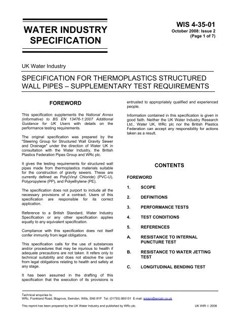
WATER INDUSTRYSPECIFICATION<strong>WIS</strong> 4-<strong>35</strong>-<strong>01</strong>October 2008: Issue 2(Page 1 of 7)<strong>UK</strong> <strong>Water</strong> IndustrySPECIFICATION FOR THERMOPLASTICS STRUCTUREDWALL PIPES – SUPPLEMENTARY TEST REQUIREMENTSFOREWORDThis specification supplements the National Annex(informative) to BS EN 13476-1:2007 AdditionalGuidance for <strong>UK</strong> Users with details on theperformance testing requirements.The original specification was prepared by the"Steering Group for Structured Wall Gravity Sewerand Drainage" under the direction of <strong>Water</strong> <strong>UK</strong> inconsultation with the <strong>Water</strong> Industry, the BritishPlastics Federation Pipes Group and WRc plc.It gives the testing requirements for structured wallpipes made from thermoplastics materials suitablefor the construction of gravity sewers. These arecurrently defined as Poly(Vinyl Chloride) (PVC-U),Polypropylene (PP), and Polyethylene (PE).The specification does not purport to include all thenecessary provisions of a contract. Users of thisspecification are responsible for its correctapplication.Reference to a British Standard, <strong>Water</strong> IndustrySpecification or any other specification appliesequally to any equivalent specification.Compliance with this specification does not itselfconfer immunity from legal obligations.This specification calls for the use of substancesand/or procedures that may be injurious to health ifadequate precautions are not taken. It refers only totechnical suitability and does not absolve the userfrom legal obligations relating to health and safety atany stage.entrusted to appropriately qualified and experiencedpeople.Information contained in this specification is given ingood faith. Neither the <strong>UK</strong> <strong>Water</strong> Industry ResearchLtd., <strong>Water</strong> <strong>UK</strong>, WRc plc nor the British PlasticsFederation can accept any responsibility for actionstaken as a result.FOREWORD1. SCOPE2. DEFINITIONSCONTENTS3. PERFORMANCE TESTS4. TEST CONDITIONS5. REFERENCESA. RESISTANCE TO INTERNALPUNCTURE TESTB. RESISTANCE TO WATER JETTINGTESTC. LONGITUDINAL BENDING TESTIt has been assumed in the drafting of thisspecification that the execution of its provisions isTechnical enquiries to:WRc, Frankland Road, Blagrove, Swindon, Wilts, SN5 8YF Tel: (<strong>01</strong>793) 865151 E-mail: wisign@wrcplc.co.ukThis reprint has been prepared by the <strong>UK</strong> <strong>Water</strong> Industry and published by WRc plc. <strong>UK</strong> WIR © 2008
1. SCOPEThis Specification specifies the materials,performance and test requirements forthermoplastics structured wall pipe and joints havinga smooth bore for gravity sewers in nominal sizes of150 to 900.It covers pipes jointed using separate moulded orformed couplers, formed integral sockets and factoryfitted moulded couplers forming sockets which are anintegral part of the supplied pipe.2. DEFINITIONSFor the purposes of this standard, the definitionsgiven in BS EN ISO 472, BS EN 476, and BS EN ISO1043-1 apply. In addition the following definitionsapply.2.1 Thermoplastics structured wall pipes:products which have an optimised design with regardto material usage to achieve the relevantperformance requirements.2.2 Nominal size DN: a numerical designationof size of a component, which is a convenient roundnumber approximately equal to the manufacturingdimension in millimetres. This can apply to theinternal diameter (DN/ID) or external diameter(DN/OD).2.3 Intermediate layerThe layer sandwiched between solid skins producedby a multi-extrusion process.3. PERFORMANCE TESTS3.1 General RequirementsThe requirements of this section shall be met beforecompliance with this specification can be claimed. Ifthere is a change in design, in material and/or in theproduction method other than routine in-processadjustments and extensions to the product range itwill be necessary to demonstrate that therequirements of this specification are still satisfied.The type tests as listed in Table 1 shall be carried outon samples from each diameter in the manufacturer’sproduct range unless specified otherwise in thisspecificationTable 1 - Test requirements applicable fordifferent construction materialsMaterial ofConstructionTest Clause PVC-U PP PEInternalpuncture3.2 √ √ √<strong>Water</strong> jetting 3.3 √ √ √Longitudinalbending3.4 √ √ √3.2 Resistance to internal punctureNote: This test is intended to assess thetoughness/general robustness of the internal wall ofthe product.The test shall be carried out on a 150 DN pipe (or thepipe within the product range with the minimuminternal wall thickness).When tested in accordance with Appendix A, thepipe shall be capable of withstanding withoutdamage (as defined in Appendix A) a minimumimpact energy equivalent to 250 g from a 1m dropheight (2.45 Joules).3.3 Resistance to water jetting (only requiredfor diameters ≤ DN300)When tested in accordance with Appendix B of thisspecification, the pipe shall withstand a jettingpressure of 180 bar without damage as definedbelow (Note A).Note A: Damage is defined as penetration through:• the wall of the pipe for solid wall pipe andmulti layer pipe where all the layers are ofsolid construction;• the inside wall for twin wall pipe. Penetrationthrough the first inside layer of multi layerpipe where the intermediate layer is of foamor hollow construction.NOTE B: Small diameters are generally unblockedusing high pressure/low volume jetting machines.These can lead to high forces on the pipe wall.3.4 Longitudinal bendingWhen tested in accordance with Appendix C of thisspecification, the pipe shall not sag by more than 5%of the overall length of the pipe.© 20082
<strong>WIS</strong> 4-<strong>35</strong>-<strong>01</strong>October 2008: Issue 2(Page 3 of 7)The pipe shall be deemed to have failed if:(a) the difference in dimensions when measuredin the vertical axis is greater than 5% of thepipe length;(b) during the test the pipe incurs localpermanent deformation.4. TEST CONDITIONS4.1 Test ConditionsUnless otherwise specified the tests shall beconducted at a standard laboratory temperature of(23 ± 5)°C.4.2 Conditioning During Type Testing or incases of disagreementIn the case of tests in air, test pieces shall beconditioned prior to test by being kept at (23 ± 2)°C inair, for not less than 12 hours for pipes of wallthickness up to and including 12.7 mm, or not lessthan 24 hours for pipes of wall thickness greater than12.7 mm, unless otherwise specified.5. REFERENCESThis specification makes reference to the latestedition of the following publications (except whereotherwise indicated) including all addenda andrevisions.European standardsBS EN ISO 472Plastics. Vocabulary.BS EN ISO 1043-1 Plastics. Symbols andabbreviated terms. Basicpolymers and their specialcharacteristics.BS EN 476 General requirements forcomponents used indischarge pipes, drains andsewers for gravity systems.EN 13476-1Plastic piping systems fornon-pressure undergrounddrainage and sewerage.Structured-wall pipingsystems of uPVC, PP, PE.Part 1: Generalrequirementsandperformance characteristics3© 2008
APPENDIX A – RESISTANCE TOINTERNAL PUNCTURE TESTA.1 PrincipleA segment of pipe is subjected to impact on itsinternal surface whilst fully supported by its externalsurface.A.2 ApparatusA.2.1 Standard drop weight pipe testing apparatuscapable of dropping a tup from a height of 1 metre.A.2.2 A 250 g tup which can be varied by 25 gmultiples with a striker consisting of a steel rod atleast 25 mm in length, 5 mm in diameter and with a2.5 mm radiused hemispherical end.A.2.3 A 250 mm x 250 mm box containing dryLeighton Buzzard sand (Garside quarry) such thatthere is at least 100 mm of sand beneath the testspecimen when bedded down.Typically:ClassLower GreensandSpecific Gravity 2.65 Mg/m 3Uncompacted bulk density 1560 kg/m 3Nominal size1-2 mmCoefficient of uniformity
<strong>WIS</strong> 4-<strong>35</strong>-<strong>01</strong>October 2008: Issue 2(Page 5 of 7)APPENDIX B – RESISTANCE TOWATER JETTING TESTB.1 ApparatusSuitable means of measuring the orifice diameter inthe jet nozzle to an accuracy of 0.002 mm.Suitable means of measuring the angle of the nozzleto the pipe wall to an accuracy of 0.1°.B.1.1Pump UnitB.2 Test pieceThe pump shall be a reciprocating piston pumpcapable of delivering at least <strong>35</strong>0 bar at 9 gallons perminute of water pressure e.g. Neolith Super Series 6.The hose length shall be approximately 90 m and of15 mm (half inch) internal diameter. There shall beno sign of leakage from any part of hose or fittings.The test piece shall be a 300 mm long section of pipeof the pipe size to be tested. The test piece shall bemarked off longitudinally along the pipe into 8equidistant sections and numbered. The markingshall be waterproof.B.1.2Jetting nozzleThe jetting nozzle shall be manufactured fromstainless steel. The orifice diameter shall be 1.5 mm.All dimensions and material shall be as stated inFigure B.1.B.1.3Pressure gaugeThe pressure gauge shall be calibrated and capableof measuring to at least <strong>35</strong>0 bar to an accuracy of ± 5bar. The gauge should be connected to the watersupply immediately before the nozzle.B.1.4Test rigThe test rig shall be capable of withstandingpressures of at least <strong>35</strong>0 bar (5000 psi).It shall also be capable of:• clamping the nozzle at a constant vertical standoff distance of 5 mm (± 0.5) mm from the insidesurface of the pipe sample (Figure B.2);• holding the nozzle at an angle of (30 ± 1)° tothe inside surface of the pipe sample as shownin Figure B.2;• maintaining a fixed jet of water throughout thetest period;• holding the test piece stationary throughout thetest periodB.1.5Measuring equipmentSuitable means of checking the vertical stand offdistance between the internal pipe surface and thejet orifice (e.g. slips – with radiused bottom – FigureB.3).Figure B.3 – Measurement of stand-off distanceB.3 Procedure to identify the pressure limitB.3.1 Run the pump for a period of approximately5 minutes at full pressure or until all air has beenpurged from the supply and the pump is stabilised.The temperature of the water shall be (15 ± 10)°C.B.3.2 Stop the pump, place the test piece in the rigand secure so that the sample can not move whenunder test. Align the pipe with one of the markedsections in the jetting area. Record the segmentnumber.B.3.3 Start the pump and increase the pressure tothe test pressure uniformly over a time period of notless than 10 seconds and not more than 15 seconds.B.3.4 The test pressure shall be applied to thepipe surface for 120 seconds. Record the testpressure. If there is evidence to suggest the testpressure was not within the required tolerance (± 5bar) then the test shall be aborted.5© 2008
Figure B.1 – Nozzle for jetting rigFigure B.2 – Schematic of test rig© 20086
<strong>WIS</strong> 4-<strong>35</strong>-<strong>01</strong>October 2008: Issue 2(Page 7 of 7)B.3.5 After 120 seconds stop the water jet.Remove the test piece from the rig, inspect for signsof damage, and record pass or fail in accordancewith Clause 3.3.B.3.6 The test shall be repeated 5 times insuccession at the test pressure. The pipe sampleshall be turned to an untested segment for each test.If there is no unacceptable damage from these fiveconsecutive tests then the pipe is considered to havepassed at that pressure.B.3.7 If unacceptable damage is apparent in oneof the five consecutive tests the pipe is considered tohave failed the test. A further 5 tests shall be carriedout at a lower pressure. The five consecutive testsshall not be repeated at the same pressure.B.3.8 If all five of the further consecutive testsshow no unacceptable damage, the pressure limit isconfirmed.B.4 Test ReportThe test report shall include:• identification of the sample;• whether the requirements of Clause 3.3 aremet.APPENDIX C – LONGITUDINALBENDING TESTC.1 PrincipleThe maximum length of pipe as sold by themanufacturer is placed on two end supports and theamount of sag measured.The test is intended to eliminate very flexible pipe(e.g. coilable pipe) and pipe which is so weak that itmight deform when being handled on site.C.2 ApparatusTwo support blocks at least 250 mm wide and ofsufficient height to allow the pipe to sag over itslength without touching the ground. Typically thiscould consist of standard building blocks stood ontheir ends.A means of measuring the vertical distance betweenthe pipe at the centre of the span and a fixed point ofreference (ground) to an accuracy of ± 5 mm.C.3 Test specimensThe length of pipe shall be conditioned for at least1 hour in accordance with 4.1.C.4 MethodThe supports are set at a distance apart equal to thelength of pipe minus 500 mm.Place the pipe symmetrically on the supports.Measure the distance between the top of thesupports and the ground or to any fixed referencepoint in the vertical axis through the centre line of thepipe.After a period of two minutes measure the distancebetween the centre line of the pipe at mid span andthe fixed reference point. Record the difference inreadings as a percentage of pipe length.7© 2008
![Corporate social responsibility [CSR] has different ... - Water UK](https://img.yumpu.com/51398482/1/184x260/corporate-social-responsibility-csr-has-different-water-uk.jpg?quality=85)