

0 - ericssonhistory.com
0 - ericssonhistory.com
0 - ericssonhistory.com
- No tags were found...

Create successful ePaper yourself
Turn your PDF publications into a flip-book with our unique Google optimized e-Paper software.
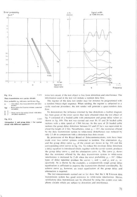
\Error probabilityPe'10A[db]Signal widthat 1500 bits/sec.in75-t32-•6//\ ( \ i\ i > '\ 1T 3\ \\ \\ \ \ \\ VA\0.5-0.4-0.3-02-0.1\ \\\ \ \\ \ \\\Po\\\\\PSF\ \\ \N \\ \ \ \ \N / ^ 2T l- - > — - - 'T BFP1P2P3A3nns2 Rmr[db]Signal-tonoise-ratio-^ —-—"'A2A,ABFIf [kc/s]FrequencyFig. 11a x 8;Data transmission over carrier circuitsError probability pe with noise interferencePuPBF';!Fig. 11 bRmrTest object, free from distortion and interferenceError curves for 2 carrier systems connectedin tandem- Error curves for carrier circuit with differentphase equalizersX8373Attenuation A and group delay T for carriercircuit with different equalizersnoise test circuit, if the test object is free from distortion and interference. Theinformation used in the test will imitate a random data flow.The register of the data test sender may for instance be programmed witha random binary-digit sequence. When sending, the register is subjected to acyclic read-out procedure; the test sender will generate a quasi-random dataflow.To demonstrate the influence exterted by line distortions a further diagramhas been given of the error curves that were obtained when the test object offig. 4 consisted of a loaded cable with attenuation and group delay values asshown in fig. 10b. The test was carried out over 10, 15 and 20 loaded cablesections with a data speed of 1 500 bits/sec. In the case of 20 loaded cablesections the group delay distortion between 0.9 and 2.5 kc/s was equivalent toabout the length of 2 bits. Nevertheless, when /?,. = 10 :! , the resistance offeredby the data transmission system to white-noise disturbances was reduced byonly 2.5 db in <strong>com</strong>parison with a distortion-free data circuit.By permission of the Royal Board of Tele<strong>com</strong>munications, tests have beenmade over two carrier systems connected in tandem. The attenuation A BFand the group delay curve i BF of the circuit are shown in fig. lib and thecorresponding error curves in fig. 11a. To reduce the envelope delay distortiona delay equalizer is introduced which, together with the carrier system, producesthe group delay curve TJ and the attenuation curve A x . The curve p, showsthat the resistance offered by the data transmission system to white-noiseinterference is increased by 2 db when the error probability p,. = 10 '•'•. Othertypes of delay equalizer produce the curves r 2 and T S and p 2 and p 3 , respectively.As is shown by the examples, a <strong>com</strong>paratively rough group delayequalization is sufficient to improve the transmission channel considerably. Toachieve curve p 0 , however, an exact equalization of the group delay andattenuation is required.The test measurements carried out so far show that the L M Ericsson datatransmission system has good resistance to white-noise interference. Hence,satisfactory data transmission can be obtained by using this system over telephonecircuits which are subject to distortion and interference.71


