

0 - ericssonhistory.com
0 - ericssonhistory.com
0 - ericssonhistory.com
- No tags were found...

You also want an ePaper? Increase the reach of your titles
YUMPU automatically turns print PDFs into web optimized ePapers that Google loves.
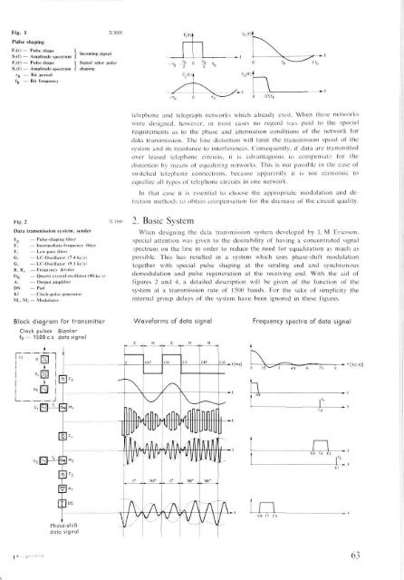
Fig. 1Pulse shapingX8366Fi(t) — Pulse shape> In<strong>com</strong>ing signalSi(f) — Amplitude spectrumFB(t) — Pulse shape 1 Signal after pulseS..(f) — Amplitude spectrum I shapingT^ — Bit period•h Bit frequency-Tb 0 Tb0 05fbtelephone and telegraph networks which already exist. When these networkswere designed, however, in most cases no regard was paid to the specialrequirements as to the phase and attenuation conditions of the network fordata transmission. The line distortion will limit the transmission speed of thesystem and its resistance to interferences. Consequently, if data are transmittedover leased telephone circuits, it is advantageous to <strong>com</strong>pensate for thedistortion by means of equalizing networks. This is not possible in the case ofswitched telephone connections, because apparently it is not economic toequalize all types of telephone circuits in one network.In that case it is essential to choose the appropriate modulation and detectionmethods to obtain <strong>com</strong>pensation for the decrease of the circuit quality.Fig. 2Data transmission system, senderFp— Pulse-shaping filterFi — Intermediate-frequency filterF2 — Low-pass filterG, — LC-Oscillator (7.4 ke/s)G: — LC-Oscillator (9.1 kc/s)R. Rv — Frequency dividerGj< — Quartz crystal oscillator (96 kc/s)Ai — Output amplifierDS — PadKl — Clock-pulse generatorMi, Mo — Modulator2. Basic SystemWhen designing the data transmission system developed by L M Ericsson,special attention was given to the desirability of having a concentrated signalspectrum on the line in order to reduce the need for equalization as much aspossible. This has resulted in a system which uses phase-shift modulationtogether with special pulse shaping at the sending end and synchronousdemodulation and pulse regeneration at the receiving end. With the aid offigures 2 and 4, a detailed description will be given of the function of thesystem at a transmission rate of 1500 bauds. For the sake of simplicity theinternal group delays of the system have been ignored in these figures.Block diagram for transmitterClock pulses Bipolarfb = 1500 c/s data signalWaveforms of data signalFrequency spectra of data signalt[ms]0 1.5 3 4 5 6 7 5 9ht [kc/s]nPhase-shifldata signalraJ * .0 63


