

0 - ericssonhistory.com
0 - ericssonhistory.com
0 - ericssonhistory.com
- No tags were found...

You also want an ePaper? Increase the reach of your titles
YUMPU automatically turns print PDFs into web optimized ePapers that Google loves.
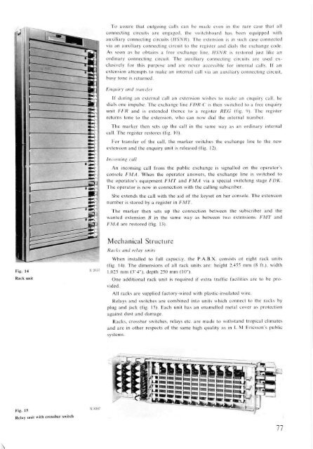
\To assure that outgoing calls can be made even in the rare case that allconnecting circuits are engaged, the switchboard has been equipped withauxiliary connecting circuits (HSNR). The extension is in such case connectedvia an auxiliary connecting circuit to the register and dials the exchange code.As soon as he obtains a free exchange line, HSNR is restored just like anordinary connecting circuit. The auxiliary connecting circuits are used exclusivelyfor this purpose and are never accessible for internal calls. If anextension attempts to make an internal call via an auxiliary connecting circuit,busy tone is returned.Enquiry and transferIf during an external call an extension wishes to make an enquiry call, hedials one impulse. The exchange line FDR-C is then switched to a free enquiryunit FFR and is extended thence to a register REG (fig. 9). The registerreturns tone to the extension, who can now dial the internal number.The marker then sets up the call in the same way as an ordinary internalcall. The register restores (fig. 10).For transfer of the call, the marker switches the exchange line to the newextension and the enquiry unit is released (fig. 12).In<strong>com</strong>ing callAn in<strong>com</strong>ing call from the public exchange is signalled on the operator'sconsole FMA. When the operator answers, the exchange line is switched tothe operator's equipment FMT and FMA via a special switching stage FDKThe operator is now in connection with the calling subscriber.She extends the call with the aid of the keyset on her console. The extensionnumber is stored by a register in FMT.The marker then sets up the connection between the subscriber and thewanted extension B in the same way as between two extensions. FMT andFMA are restored (fig. 13).Fig. 14Rack unitMechanical StructureRacks and relay unitsWhen installed to full capacity, the P.A.B.X. consists ot eight rack units(fig. 14). The dimensions of all rack units are: height 2.455 mm (8 ft.), width1,025 mm (3'4"), depth 250 mm (10").One additional rack unit is required if extra traffic facilities are to be provided.All racks are supplied factory-wired with plastic-insulated wire.Relays and switches are <strong>com</strong>bined into units which connect to the racks byplug and jack (fig. 15). Each unit has an enamelled metal cover as protectionagainst dust and damage.Racks, crossbar switches, relays etc. are made to withstand tropical climatesand are in other respects of the same high quality as in L M Ericsson's publicsystems.Fig. 15Relay unit with crossbar switch77


