VEGAPULS WL 61 - 4 ⦠20 mA/HART - two-wire
VEGAPULS WL 61 - 4 ⦠20 mA/HART - two-wire
VEGAPULS WL 61 - 4 ⦠20 mA/HART - two-wire

You also want an ePaper? Increase the reach of your titles
YUMPU automatically turns print PDFs into web optimized ePapers that Google loves.
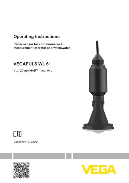
Operating InstructionsRadar sensor for continuous levelmeasurement of water and wastewater<strong>VEGAPULS</strong> <strong>WL</strong> <strong>61</strong>4 … <strong>20</strong> <strong>mA</strong>/<strong>HART</strong> - <strong>two</strong>-<strong>wire</strong>Document ID: 380<strong>61</strong>
Quick startQuick startMountingThe quick start enables a quick setup with many applications. Youcan find further information in the respective chapters of the operatinginstructions manual.1. Distance antenna to vessel wall > <strong>20</strong>0 mm2. Orientation with mounting strap> <strong>20</strong>0 mm(7.87")Fig. 1: Distance antenna to vessel wall, orientation with mounting strapConnect electricallyFor further information see chapter "Mounting".1. Make sure that the power supply corresponds to the specificationson the type label.2. Connect the instrument according to the following illustration:1Fig. 2: Wire assignment fix-connected connection cable1 brown (+) and blue (-) to power supply or to the processing system2 Shielding2Set parametersFor further information see chapter "Connecting to power supply".1. Connect interface adapter2. Start PACTware and then start the "VEGA project assistant".3. Start the setup assistant in the DTM window and carry out thepredetermined steps.Parameterization exampleThe radar sensor measures the distance from the sensor to theproduct surface. For indication of the real level, an allocation of themeasured distance to the percentage height must be carried out.2<strong>VEGAPULS</strong> <strong>WL</strong> <strong>61</strong> • 4 … <strong>20</strong> <strong>mA</strong>/<strong>HART</strong> - <strong>two</strong>-<strong>wire</strong>380<strong>61</strong>-EN-121011
Quick start0,5 m(19.68")100%25 m(196.85")0%1Fig. 3: Parameterization example1 Min. level = max. meas. distance2 Max. level = min. meas. distanceFurther stepsFor this adjustment, the distance is entered for min. and max. level.If these values are not known, an adjustment with distances, forexample, of 10 % and 90 % is also possible. Starting point for thesedistance specifications is always the seal surface of the flange.1. In the menu "Additional settings", menu item "Damping" you haveto adjust the requested damping of the output signal.2. Select the output characteristics in the menu item "Current output".The quick start is then finished. For further information see chapter"Set up with PACTware".380<strong>61</strong>-EN-121011<strong>VEGAPULS</strong> <strong>WL</strong> <strong>61</strong> • 4 … <strong>20</strong> <strong>mA</strong>/<strong>HART</strong> - <strong>two</strong>-<strong>wire</strong>3
ContentsContents1 About this document1.1 Function ............................................................................. <strong>61</strong>.2 Target group ....................................................................... <strong>61</strong>.3 Symbolism used ................................................................. 62 For your safety2.1 Authorised personnel ......................................................... 72.2 Appropriate use .................................................................. 72.3 Warning about incorrect use ............................................... 72.4 General safety instructions ................................................. 72.5 CE conformity ..................................................................... 82.6 NAMUR recommendations ................................................ 82.7 Radio license for Europe .................................................... 82.8 Environmental instructions ................................................. 83 Product description3.1 Configuration .................................................................... 103.2 Principle of operation ........................................................ 113.3 Packaging, transport and storage ..................................... 113.4 Accessories and replacement parts ................................. 124 Mounting4.1 General instructions ......................................................... 134.2 Mounting versions ............................................................ 134.3 Mounting preparations, mounting strap ............................ 164.4 Instructions for installation ................................................ 175 Connecting to power supply5.1 Preparing the connection ................................................. 235.2 Wiring plan ....................................................................... 235.3 Switch-on phase ............................................................... 236 Set up with VEGADIS 626.1 Connection ....................................................................... 256.2 Adjust the sensor .............................................................. 256.3 Scale the indication .......................................................... 267 Setup with PACTware7.1 Connect the PC ................................................................ 287.2 Parameter adjustment with PACTware .............................. 297.3 Saving the parameter adjustment data ............................. 318 Set up with other systems8.1 DD adjustment programs ................................................. 328.2 Communicator 375, 475 ................................................... 3249 Diagnosis, Asset Management and service9.1 Maintenance .................................................................... 339.2 Measured value and event memory ................................. 339.3 Asset Management function ............................................. 349.4 Rectify faults ..................................................................... 379.5 Software update ............................................................... 419.6 How to proceed in case of repair ...................................... 41<strong>VEGAPULS</strong> <strong>WL</strong> <strong>61</strong> • 4 … <strong>20</strong> <strong>mA</strong>/<strong>HART</strong> - <strong>two</strong>-<strong>wire</strong>380<strong>61</strong>-EN-121011
Contents10 Dismounting10.1 Dismounting steps ............................................................ 4310.2 Disposal ........................................................................... 4311 Supplement11.1 Technical data .................................................................. 4411.2 Radio astronomy stations ................................................. 4911.3 Dimensions ...................................................................... 49380<strong>61</strong>-EN-121011<strong>VEGAPULS</strong> <strong>WL</strong> <strong>61</strong> • 4 … <strong>20</strong> <strong>mA</strong>/<strong>HART</strong> - <strong>two</strong>-<strong>wire</strong>Safety instructions for Ex areasPlease note the Ex-specific safety information for installation and operationin Ex areas. These safety instructions are part of the operatinginstructions manual and come with the Ex-approved instruments.Editing status: <strong>20</strong>12-09-275
1 About this document1 About this document1.1 FunctionThis operating instructions manual provides all the information youneed for mounting, connection and setup as well as important instructionsfor maintenance and fault rectification. Please read this informationbefore putting the instrument into operation and keep this manualaccessible in the immediate vicinity of the device.1.2 Target groupThis operating instructions manual is directed to trained qualifiedpersonnel. The contents of this manual should be made available tothese personnel and put into practice by them.1.3 Symbolism usedInformation, tip, noteThis symbol indicates helpful additional information.Caution: If this warning is ignored, faults or malfunctions can result.Warning: If this warning is ignored, injury to persons and/or seriousdamage to the instrument can result.Danger: If this warning is ignored, serious injury to persons and/ordestruction of the instrument can result.Ex applicationsThis symbol indicates special instructions for Ex applications.• ListThe dot set in front indicates a list with no implied sequence.→ ActionThis arrow indicates a single action.1 SequenceNumbers set in front indicate successive steps in a procedure.Battery disposalThis symbol indicates special information about the disposal of batteriesand accumulators.6<strong>VEGAPULS</strong> <strong>WL</strong> <strong>61</strong> • 4 … <strong>20</strong> <strong>mA</strong>/<strong>HART</strong> - <strong>two</strong>-<strong>wire</strong>380<strong>61</strong>-EN-121011
2 For your safety2 For your safety2.1 Authorised personnelAll operations described in this operating instructions manual mustbe carried out only by trained specialist personnel authorised by theplant operator.During work on and with the device the required personal protectiveequipment must always be worn.2.2 Appropriate use<strong>VEGAPULS</strong> <strong>WL</strong> <strong>61</strong> is a sensor for continuous level measurement.You can find detailed information on the application range in chapter"Product description".Operational reliability is ensured only if the instrument is properlyused according to the specifications in the operating instructionsmanual as well as possible supplementary instructions.2.3 Warning about incorrect useInappropriate or incorrect use of the instrument can give rise toapplication-specific hazards, e.g. vessel overfill or damage to systemcomponents through incorrect mounting or adjustment.380<strong>61</strong>-EN-121011<strong>VEGAPULS</strong> <strong>WL</strong> <strong>61</strong> • 4 … <strong>20</strong> <strong>mA</strong>/<strong>HART</strong> - <strong>two</strong>-<strong>wire</strong>2.4 General safety instructionsThis is a state-of-the-art instrument complying with all prevailingregulations and guidelines. The instrument must only be operated in atechnically flawless and reliable condition. The operator is responsiblefor the trouble-free operation of the instrument.During the entire duration of use, the user is obliged to determine thecompliance of the necessary occupational safety measures with thecurrent valid rules and regulations and also take note of new regulations.The safety instructions in this operating instructions manual, the nationalinstallation standards as well as the valid safety regulations andaccident prevention rules must be observed by the user.For safety and warranty reasons, any invasive work on the devicebeyond that described in the operating instructions manual may becarried out only by personnel authorised by the manufacturer. Arbitraryconversions or modifications are explicitly forbidden.The safety approval markings and safety tips on the device must alsobe observed.Depending on the instrument version, the emitting frequencies are inthe C or K band range. The low emitting frequencies are far below theinternationally approved limit values. When used correctly, there is nodanger to health.7
2 For your safety2.5 CE conformityThe device fulfills the legal requirements of the applicable EC guidelines.By affixing the CE marking, we confirm successful testing of theproduct.You can find the conformity certificate in the download section of ourhomepage.2.6 NAMUR recommendationsNAMUR is the automation technology user association in the processindustry in Germany. The published NAMUR recommendations areaccepted as the standard in field instrumentation.The device fulfills the requirements of the following NAMUR recommendations:• NE 43 – Signal level for malfunction information from measuringtransducers• NE 53 – Compatibility of field devices and indicating/adjustmentcomponents• NE 107 - Self-monitoring and diagnosis of field devicesFor further information see www.namur.de.2.7 Radio license for EuropeThe instrument meets the LPR (Level Probing Radar) radio standardEN 302729-1/2. It is approved for unrestricted use inside and outsideof closed vessels in countries of the EU and EFTA that have implementedthis standard: Austria, Belgium, Bulgaria, Germany, Denmark,Estonia, France, Greece, Great Britain, Ireland, Island, Italy, Liechtenstein,Lithuania, Latvia, Luxembourg, Malta, Netherlands, Norway,Poland, Portugal, Romania, Sweden, Switzerland, Slovakia, Slovenia,Spain, Czech Republik and Cyprus.Not included in the CE confirmity declaration are the countries implementingthis radio standard at a later date: Finland and Hungary.For operation outside of closed vessels, the following conditions mustbe fulfilled:• The installation must be carried out by trained qualified personnel• The instrument must be stationary mounted and the antennadirected vertically downward• The mounting location must be at least 4 km away from the radioastronomy stations listed in the supplement, unless special permissionwas granted by the responsible national approval authority• When installed within 4 to 40 km of one of the radio astronomy stationslisted in the supplyment, the instrument must not be mountedhigher than 15 m above the ground.82.8 Environmental instructionsProtection of the environment is one of our most important duties.That is why we have introduced an environment management systemwith the goal of continuously improving company environmental pro-<strong>VEGAPULS</strong> <strong>WL</strong> <strong>61</strong> • 4 … <strong>20</strong> <strong>mA</strong>/<strong>HART</strong> - <strong>two</strong>-<strong>wire</strong>380<strong>61</strong>-EN-121011
2 For your safetytection. The environment management system is certified accordingto DIN EN ISO 14001.Please help us fulfil this obligation by observing the environmentalinstructions in this manual:• Chapter "Packaging, transport and storage"• Chapter "Disposal"380<strong>61</strong>-EN-121011<strong>VEGAPULS</strong> <strong>WL</strong> <strong>61</strong> • 4 … <strong>20</strong> <strong>mA</strong>/<strong>HART</strong> - <strong>two</strong>-<strong>wire</strong>9
3 Product description3 Product descriptionType label3.1 ConfigurationThe type label contains the most important data for identification anduse of the instrument:123456789101<strong>61</strong>514131211Fig. 4: Layout of the type label (example)1 Instrument type2 Product code3 Approvals4 Power supply and signal output, electronics5 Protection rating6 Measuring range7 Process and ambient temperature, process pressure8 Material, wetted parts9 Hardware and software version10 Order number11 Serial number of the instrument12 Symbol of the device protection class13 ID numbers, instrument documentation14 Note to observe the instrument documentation15 Notified authority for CE marking16 Approval directiveSerial numberScope of this operatinginstructions manual10With the serial number of the instrument on the type label you haveaccess to the following data on our homepage:Article number of the instrument (HTML)Delivery date (HTML)Order-specific instrument features (HTML)• Operating instructions at the time of shipment (PDF)Order-specific sensor data for an electronics exchange (XML)• Test certificate "Measuring Accuracy" (PDF)For this purpose, move to www.vega.com and "VEGA Tools".This operating instructions manual applies to the following instrumentversions:• Hardware from 1.0.0• Software from 4.4.0<strong>VEGAPULS</strong> <strong>WL</strong> <strong>61</strong> • 4 … <strong>20</strong> <strong>mA</strong>/<strong>HART</strong> - <strong>two</strong>-<strong>wire</strong>380<strong>61</strong>-EN-121011
3 Product descriptionScope of deliveryApplication areaFunctional principlePackagingTransportTransport inspectionThe scope of delivery encompasses:• Radar sensor• Compression flange (option)•Mounting strap with fixing material (optional)• Documentation– this operating instructions manual– Ex-specific "Safety instructions" (with Ex versions)– if necessary, further certificates3.2 Principle of operationThe radar sensor <strong>VEGAPULS</strong> <strong>WL</strong> <strong>61</strong> is the ideal sensor for all applicationsin the water and waste water industry. It is particularly suitablefor level measurement in water treatment, in pump stations as well asstorm water overflow tanks, for flow measurement in open flumes andfor gauge measurement.The antenna of the radar sensor emits short radar pulses with aduration of approx. 1 ns. These pulses are reflected by the productand received by the antenna as echoes. The transit time of the radarpulses from emission to reception is proportional to the distance andhence to the level. The determined level is converted into an appropriateoutput signal and outputted as measured value.3.3 Packaging, transport and storageYour instrument was protected by packaging during transport. Itscapacity to handle normal loads during transport is assured by a testaccording to DIN EN 24180.The packaging of standard instruments consists of environmentfriendly,recyclable cardboard. For special versions, PE foam or PEfoil is also used. Dispose of the packaging material via specialisedrecycling companies.Transport must be carried out under consideration of the notes on thetransport packaging. Nonobservance of these instructions can causedamage to the device.The delivery must be checked for completeness and possible transitdamage immediately at receipt. Ascertained transit damage or concealeddefects must be appropriately dealt with.380<strong>61</strong>-EN-121011Storage<strong>VEGAPULS</strong> <strong>WL</strong> <strong>61</strong> • 4 … <strong>20</strong> <strong>mA</strong>/<strong>HART</strong> - <strong>two</strong>-<strong>wire</strong>Up to the time of installation, the packages must be left closed andstored according to the orientation and storage markings on theoutside.Unless otherwise indicated, the packages must be stored only underthe following conditions:Not in the open• Dry and dust freeNot exposed to corrosive media• Protected against solar radiation• Avoiding mechanical shock and vibration11
3 Product descriptionStorage and transporttemperatureInterface adapterExternal indicating andadjustment unit with<strong>HART</strong> protocol• Storage and transport temperature see chapter "Supplement -Technical data - Ambient conditions"• Relative humidity <strong>20</strong> … 85 %3.4 Accessories and replacement partsThe interface adapter VEGACONNECT enables the connection ofcommunication-capable instruments to the USB interface of a PC. Forparameter adjustment of these instruments, an adjustment softwaresuch as PACTware with VEGA-DTM is required.You can find further information in the operating instructions "Interfaceadapter VEGACONNECT" (Document-ID 32628).VEGADIS 62 is suitable for measured value indication and adjustmentof sensors with <strong>HART</strong> protocol. It is looped into the 4 … <strong>20</strong> <strong>mA</strong>/<strong>HART</strong>signal cable.You can find further information in the operating instructions "VE-GADIS 62" (Document-ID 36469).12<strong>VEGAPULS</strong> <strong>WL</strong> <strong>61</strong> • 4 … <strong>20</strong> <strong>mA</strong>/<strong>HART</strong> - <strong>two</strong>-<strong>wire</strong>380<strong>61</strong>-EN-121011
4 Mounting4 MountingSuitability for the processconditionsStraining clamp4.1 General instructionsMake sure that all parts of the instrument exposed to the process, inparticular the active measuring component, process seal and processfitting, are suitable for the existing process conditions. These includeabove all the process pressure, process temperature as well as thechemical properties of the medium.You can find the specifications in chapter "Technical data" and on thetype label.4.2 Mounting versionsMost simply mount the instrument via the straining clamp. For thispurpose, the connection cable is provided with a strain relief <strong>wire</strong> ofKevlar.In order to avoid faulty measured values, make sure that the sensordoes not oscillate.> <strong>20</strong>0 mm(7.87")Fig. 5: Mounting via a straining clampMounting bracketFor a rigid mounting, a mounting bracket with opening for threadG1½, e.g. from the VEGA product range, is recommended. Themounting of the sensor in the bracket is carried out via a G1½ counternut of plastic. Take note of chapter "Mounting instructions" for thedistance to the wall.380<strong>61</strong>-EN-121011<strong>VEGAPULS</strong> <strong>WL</strong> <strong>61</strong> • 4 … <strong>20</strong> <strong>mA</strong>/<strong>HART</strong> - <strong>two</strong>-<strong>wire</strong>13
4 Mounting> <strong>20</strong>0 mm(7.87")Fig. 6: Mounting via a mounting bracketMounting strapThe optional mounting strap enables sensor mounting on e.g. a ceiling,wall or bracket. It is available in the following versions:• Length 300 mm for ceiling mounting• Length 170 mm for wall mountingThe instrument is normally mounted vertically on the ceiling.This ensures swivelling of the sensor up to 180° for optimum orientation.Fig. 7: Vertical mounting on the ceiling via the mounting strap with length300 m<strong>mA</strong>s an alternative, mounting can be carried out vertically on the wall.14<strong>VEGAPULS</strong> <strong>WL</strong> <strong>61</strong> • 4 … <strong>20</strong> <strong>mA</strong>/<strong>HART</strong> - <strong>two</strong>-<strong>wire</strong>380<strong>61</strong>-EN-121011
4 Mounting> <strong>20</strong>0 mm(7.87")Fig. 8: Vertical mounting on the wall via the mounting strap with length 170 mmSome measuring points have only very little space between ceilingand water surface. In such cases, for example in closed stormoverflow basins, horizontal mounting of the sensor is recommended.The radar impulses must be directed via a 45° reflector - for examplea stainless steel sheet - to the water surface.45°> 50 mm(1.97")Fig. 9: Horizontal mounting with a mounting strap of length 170 mm with reflectorprovided by the customerInformation:With this mounting arrangement, the reference plane mentioned inchapter "Technical data" no longer applies. There is an offset thatmust be taken into account for the adjustment. Note the distancemeasured at min. level with the reflector, for example 2.5 m. Enterthis value as min. adjustment/measuring range begin. Determine thedifference between the min. and max. level, for example 1 m. The distancefor the max. adjustment results from 2.5 m - 1 m = 1.5 m. Enterthis value as max. adjustment/measuring range end.380<strong>61</strong>-EN-121011<strong>VEGAPULS</strong> <strong>WL</strong> <strong>61</strong> • 4 … <strong>20</strong> <strong>mA</strong>/<strong>HART</strong> - <strong>two</strong>-<strong>wire</strong>15
4 Mounting1Fig. 10: Horizontal mounting with the optional mounting strap with integratedreflector1 Reference planeInformation:With this combination (by default), the offset is already taken into account.The lower side of the mountng seal is the reference plane.FlangeFor mounting the instrument on a socket or a manhole cover, an unassembledcombination compression flange is optionally available forDN 80 (ASME 3" or JIS 80), also as a retrofitting part. As an alternative,the instrument can be already supplied with a tight, fix-mountedadapter flange from DN 100 (ASME 4" or JIS 100).You can find drawings of these mounting options in chapter "Dimensions".Fig. 11: Mounting by means of an adapter flange, for example, on a manhole lid.164.3 Mounting preparations, mounting strapThe optional mounting strap is supplied unassembled. It must bescrewed to the sensor before setup with the attached screws. Max.torque, see chapter "Technical data". Required tools: Allen wrenchsize 4.There are <strong>two</strong> different ways of screwing the strap to the sensor.Depending on the selected method, the sensor can be rotated inthe strap infinitely variable through 180° or in three steps 0°, 90° and180°.<strong>VEGAPULS</strong> <strong>WL</strong> <strong>61</strong> • 4 … <strong>20</strong> <strong>mA</strong>/<strong>HART</strong> - <strong>two</strong>-<strong>wire</strong>380<strong>61</strong>-EN-121011
4 MountingFig. 12: Rotation in the centre with ceiling mountingFig. 13: Adjustment of the angle of inclination in case of wall mountingTight installation of theplastic horn antennaPolarisation plane4.4 Instructions for installationFor tight installation of the version with plastic horn antenna with compressionor adapter flange, the following conditions must be fulfilled:1. Use suitable flat seal, e.g. of EPDM with Shore hardness 25 or 502. Make sure the number of flange screws corresponds to the numberof flange holes3. Tighten all screws with the torque stated in the technical dataThe emitted radar impulses of the radar sensor are electromagneticwaves. The polarisation plane is the direction of the electrical wavecomponent. By turning the instrument in the connection flange ormounting strap, the polarisation can be used to reduce the effects offalse echoes.The position of the polarisation level is marked by marking bars on theinstrument.380<strong>61</strong>-EN-121011<strong>VEGAPULS</strong> <strong>WL</strong> <strong>61</strong> • 4 … <strong>20</strong> <strong>mA</strong>/<strong>HART</strong> - <strong>two</strong>-<strong>wire</strong>17
4 Mounting1Fig. 14: Position of the polarisation level1 Marking barInstallation positionWhen mounting the sensor, keep a distance of at least <strong>20</strong>0 mm(7.874 in) to the vessel wall. If the sensor is installed in the center ofdished or round vessel tops, multiple echoes can arise. These can,however, be suppressed by an appropriate adjustment (see chapter"Setup").If you cannot keep this distance you should carry out a false echostorage before setup. This applies mainly if buildup on the vessel wallis expected. In this case, we recommend repeating a false echo storagelater with existing buildup.> <strong>20</strong>0 mm(7.87")Fig. 15: Mounting of the radar sensor on round vessel topsIn vessels with conical bottom it can be advantageous to mount thesensor in the center of the vessel, as measurement is then possibledown to the lowest point of the vessel bottom.18<strong>VEGAPULS</strong> <strong>WL</strong> <strong>61</strong> • 4 … <strong>20</strong> <strong>mA</strong>/<strong>HART</strong> - <strong>two</strong>-<strong>wire</strong>380<strong>61</strong>-EN-121011
4 MountingFig. 16: Mounting of the radar sensor on vessels with conical bottomInflowing mediumDo not mount the instrument in or above the filling stream. Make surethat you detect the product surface, not the inflowing product.Fig. 17: Mounting of the radar sensor with inflowing mediumSocketApproximate values of the socket heights are shown in the followingillustration. The socket end should be smooth and burr-free, if possiblealso rounded. After mounting, you have to carry out a false signalmemory during the parameter adjustment.380<strong>61</strong>-EN-121011<strong>VEGAPULS</strong> <strong>WL</strong> <strong>61</strong> • 4 … <strong>20</strong> <strong>mA</strong>/<strong>HART</strong> - <strong>two</strong>-<strong>wire</strong>19
4 Mountinghdd80 mm / 3.15"100 mm / 4"125 mm / 5"150 mm / 6"h300 mm / 11.8"500 mm / 19.69"600 mm / 23.6"800 mm / 31.5"Fig. 18: Deviating socket dimensionsSensor orientationDirect the sensor as perpendicular as possible to the product surfaceto achieve optimum measurement results.Fig. 19: Orientation of the sensorVessel installationsThe mounting location of the radar sensor should be a place where noother equipment or fixtures cross the path of the microwave signals.Vessel installations, such as e.g. ladders, limit switches, heating spirals,struts, etc., can cause false echoes and impair the useful echo.Make sure when planning your measuring site that the radar sensorhas a "clear view" to the measured product.In case of existing vessel installations, a false echo storage should becarried out during setup.If large vessel installations such as struts or supports cause falseechoes, these can be attenuated through supplementary measures.Small, inclined sheet metal baffles above the installations scatter theradar signals and prevent direct interfering reflections.<strong>20</strong>Fig. <strong>20</strong>: Cover smooth profiles with deflectors<strong>VEGAPULS</strong> <strong>WL</strong> <strong>61</strong> • 4 … <strong>20</strong> <strong>mA</strong>/<strong>HART</strong> - <strong>two</strong>-<strong>wire</strong>380<strong>61</strong>-EN-121011
4 MountingFoam generationFlow measurement withrectangular flumeThrough the action of filling, stirring and other processes in the vessel,compact foams that considerably damp the emitted signals may formon the product surface.If foams are causing measurement errors, the biggest possible radarantennas, the electronics with increased sensitivity or low frequencyradar sensors (C band) should be used.As an alternative, sensors with guided microwave can be used. Theseare unaffected by foam generation and are best suited for such applications.The short examples give you introductory information on the flowmeasurement. Detailed planning information is available from flumemanufacturers and in special literature.3 ... 4 h max≥ 50 mm90°1h maxd min90°2 3≥ 2 mm x h max4Fig. 21: Flow measurement with rectangular flume: d min.= min. distance of thesensor (see chapter "Technical data"); h max.= max. filling of the rectangularflume1 Overflow orifice (side view)2 Headwater3 Tail water4 Overfall orifice (view from bottom water)In general, the following points must be observed:Install the sensor on the headwater side• Installation in the centre of the flume and vertical to the liquidsurfaceDistance to the overfall orificeDistance of orifice opening above groundMin. distance of the orifice opening to bottom water• Min. distance of the sensor to max. storage level380<strong>61</strong>-EN-121011<strong>VEGAPULS</strong> <strong>WL</strong> <strong>61</strong> • 4 … <strong>20</strong> <strong>mA</strong>/<strong>HART</strong> - <strong>two</strong>-<strong>wire</strong>21
4 MountingFlow measurement withKhafagi Venturi flumed90°3 ... 4 x h maxh max21BFig. 22: Flow measurement with Khafagi-Venturi flume: d = Min. distance to sensor;h max.= max. filling of the flume; B = tightest constriction in the flume1 Position sensor2 Venturi flumeIn general, the following points must be observed:Installation of the sensor at the inlet side• Installation in the centre of the flume and vertical to the liquidsurfaceDistance to the Venturi flume• Min. distance of the sensor to max. storage level22<strong>VEGAPULS</strong> <strong>WL</strong> <strong>61</strong> • 4 … <strong>20</strong> <strong>mA</strong>/<strong>HART</strong> - <strong>two</strong>-<strong>wire</strong>380<strong>61</strong>-EN-121011
5 Connecting to power supply5 Connecting to power supplySafety instructionsVoltage supplyConnection cable5.1 Preparing the connectionAlways keep in mind the following safety instructions:•Connect only in the complete absence of line voltageIf overvoltage surges are expected, overvoltage arresters shouldbe installedPower supply and current signal are carried on the same <strong>two</strong>-<strong>wire</strong>cable. The voltage supply range can differ depending on the instrumentversion.The data for power supply are specified in chapter "Technical data".Provide a reliable separation between the supply circuit and themains circuits according to DIN VDE 0106 part 101.Keep in mind the following additional factors that influence the operatingvoltage:• Output voltage of the power supply unit can be lower under nominalload (with a sensor current of <strong>20</strong>.5 <strong>mA</strong> or 22 <strong>mA</strong> in case of faultmessage)•Influence of additional instruments in the circuit (see load values inchapter "Technical data")The instrument is connected with standard <strong>two</strong>-<strong>wire</strong> cable withoutscreen. If electromagnetic interference is expected which is above thetest values of EN <strong>61</strong>326-1 for industrial areas, screened cable shouldbe used.For instruments with housing and cable gland, use cable with roundcross-section. A cable outer diameter of 5 … 9 mm (0.2 … 0.35 in)ensures the seal effect of the cable gland. If you are using cable witha different diameter, exchange the seal or use a suitable cable gland.We generally recommend the use of screened cable for <strong>HART</strong> multidropmode.5.2 Wiring planWire assignment, connectioncable12380<strong>61</strong>-EN-121011<strong>VEGAPULS</strong> <strong>WL</strong> <strong>61</strong> • 4 … <strong>20</strong> <strong>mA</strong>/<strong>HART</strong> - <strong>two</strong>-<strong>wire</strong>Fig. 23: Wire assignment fix-connected connection cable1 brown (+) and blue (-) to power supply or to the processing system2 Shielding5.3 Switch-on phaseAfter connecting the instrument to power supply or after a voltagerecurrence, the instrument carries out a self-check for approx. 30 s:23
5 Connecting to power supply• Internal check of the electronics••value" on the display or PC•Indication of the instrument type, hardware and software version,measurement loop name on the display or PCIndication of the status message "F 105 Determine measuredThe output signal jumps to the set error currentAs soon as a plausible measured value is found, the correspondingcurrent is outputted to the signal cable. The value corresponds to theactual level as well as the settings already carried out, e.g. factorysetting.24<strong>VEGAPULS</strong> <strong>WL</strong> <strong>61</strong> • 4 … <strong>20</strong> <strong>mA</strong>/<strong>HART</strong> - <strong>two</strong>-<strong>wire</strong>380<strong>61</strong>-EN-121011
6 Set up with VEGADIS 626 Set up with VEGADIS 626.1 ConnectionThe VEGADIS 62 is an indicating and adjustment unit without externalenergy for looping into 4 … <strong>20</strong> <strong>mA</strong>/<strong>HART</strong> circuits.The parameter adjustment of the sensor is carried out via <strong>HART</strong> communication.During the parameter adjustment, the VEGADIS 62 actsas a Secondary Master with respect to the sensor.23=~41Fig. 24: Connection of VEGADIS 62 to the sensor1 Sensor2 VEGADIS 623 <strong>HART</strong> resistance > 150 Ω (necessary with low impedance power supply)4 Voltage supply/ProcessingThe following adjustment volume of the connected <strong>HART</strong> sensor isavailable:Min./Max. adjustment• zero/span adjustment (live adjustment)• Damping6.2 Adjust the sensorProceed as follows for the min./max. adjustment of the sensor:1. Press "OK" to reach the adjustment menu.2. Select the submenu "Measurement" and confirm with "OK".3. Move to the menu item "Unit". There the instrument unit of thesensor is displayed, for example "m".380<strong>61</strong>-EN-121011<strong>VEGAPULS</strong> <strong>WL</strong> <strong>61</strong> • 4 … <strong>20</strong> <strong>mA</strong>/<strong>HART</strong> - <strong>two</strong>-<strong>wire</strong>4. Move to the menu item "MB begin", there the max. measuringdistance is displayed, for example the default setting 15 m.25
6 Set up with VEGADIS 625. Edit value via "OK" and adjust the requested value, for example,5 m.6. Save value with "OK", <strong>VEGAPULS</strong> <strong>WL</strong> <strong>61</strong> displays briefly "Wait",then the value is taken over into the sensor.7. Move to the menu item "MB end", there the min. measuring distanceis displayed, for example the default setting 0 m.8. Proceed accordingly for "MB end", enter for example the value1 m and store.The min./max. adjustment is finished.After "[ESC]", the display shows the actually measured distance asdigital value in m and the level on the bargraph.Keep in mind that the displayed values are anticyclical. With increasingdistance, the 4 … <strong>20</strong> <strong>mA</strong> value gets smaller and vice versa.6.3 Scale the indicationProceed as follows for indication of the level as digital value in %:1. Press "OK" to reach the adjustment menu.2. Select the submenu "Measurement" and confirm with "OK".3. Select the menu item "Unit"264. Select the unit "USER" and confirm with "OK".<strong>VEGAPULS</strong> <strong>WL</strong> <strong>61</strong> • 4 … <strong>20</strong> <strong>mA</strong>/<strong>HART</strong> - <strong>two</strong>-<strong>wire</strong>380<strong>61</strong>-EN-121011
6 Set up with VEGADIS 62Information:The symbol for <strong>HART</strong> extinguishes, the <strong>HART</strong> communication isswitched off.5. Select the submenu "Indication" and confirm with "OK".6. Select the menu item "Unit" and confirm with "OK".7. Select the unit "%" and confirm with "OK".The conversion to level indication in % is finished. The unit in themenu "Measurement" must remain at "USER".After "[ESC]", the display shows the level as digital value in % and onthe bargraph. The indication values are now synchronous.380<strong>61</strong>-EN-121011<strong>VEGAPULS</strong> <strong>WL</strong> <strong>61</strong> • 4 … <strong>20</strong> <strong>mA</strong>/<strong>HART</strong> - <strong>two</strong>-<strong>wire</strong>27
7 Setup with PACTware7 Setup with PACTware7.1 Connect the PCVia interface adapter tothe signal cable2 4LOCK13TWISTOPENUSB5Fig. 25: Connecting the PC to the signal cable1 Sensor2 <strong>HART</strong> resistance 250 Ω (optional depending on processing)3 Connection cable with 2 mm pins and terminals4 Processing system/PLC/Voltage supply5 Interface adapter, for example VEGACONNECT 4Note:With power supply units with integrated <strong>HART</strong> resistance (internalresistance approx. 250 Ω), an additional external resistance is notnecessary. This applies, e.g. to the VEGA instruments VEGATRENN149A, VEGAMET 381, VEGAMET 391. Common Ex separators arealso usually equipped with a sufficient current limitation resistance. Insuch cases, the interface converter can be connected parallel to the4 … <strong>20</strong> <strong>mA</strong> cable (dashed line in the previous illustration).28<strong>VEGAPULS</strong> <strong>WL</strong> <strong>61</strong> • 4 … <strong>20</strong> <strong>mA</strong>/<strong>HART</strong> - <strong>two</strong>-<strong>wire</strong>380<strong>61</strong>-EN-121011
TWISTUSB7 Setup with PACTwareVia interface adapter tothe VEGAMET signal conditioninginstrument1 23122on%1OPENLOCKVEGAMET 3814Fig. 26: Connection of the PC to the VEGAMET signal conditioning instrument1 Sensor2 Connection cable with 2 mm pins3 Signal conditioning instrument, e.g. VEGAMET 3814 Interface adapter, for example VEGACONNECT 4Prerequisites7.2 Parameter adjustment with PACTwareFor parameter adjustment of the sensor via a Windows PC, the configurationsoftware PACTware and a suitable instrument driver (DTM)according to FDT standard are required. The up-to-date PACTwareversion as well as all available DTMs are compiled in a DTM Collection.The DTMs can also be integrated into other frame applicationsaccording to FDT standard.Note:To ensure that all instrument functions are supported, you shouldalways use the latest DTM Collection. Furthermore, not all describedfunctions are included in older firmware versions. You can downloadthe latest instrument software from our homepage. A description ofthe update procedure is also available in the Internet.Further setup steps are described in the operating instructions manual"DTM Collection/PACTware" attached to each DTM Collection andwhich can also be downloaded from the Internet. Detailed descriptionsare available in the online help of PACTware and the DTMs.380<strong>61</strong>-EN-121011<strong>VEGAPULS</strong> <strong>WL</strong> <strong>61</strong> • 4 … <strong>20</strong> <strong>mA</strong>/<strong>HART</strong> - <strong>two</strong>-<strong>wire</strong>29
7 Setup with PACTwareFig. 27: Example of a DTM viewAdjustmentSince a radar sensor is a distance measuring instrument, the distancefrom the sensor to the product surface is measured. For indication ofthe real level, an allocation of the measured distance to the percentageheight must be carried out. To perform the adjustment, enter thedistance with full and empty vessel, see the following example:0,5 m(19.68")100%25 m(196.85")30Fig. 28: Parameterization example1 Min. level = max. meas. distance2 Max. level = min. meas. distance<strong>VEGAPULS</strong> <strong>WL</strong> <strong>61</strong> • 4 … <strong>20</strong> <strong>mA</strong>/<strong>HART</strong> - <strong>two</strong>-<strong>wire</strong>0%1380<strong>61</strong>-EN-121011
7 Setup with PACTwareIf these values are not known, an adjustment with the distances of forexample 10 % and 90 % is possible. Starting point for these distancespecifications is always the seal surface of the thread or flange. Bymeans of these settings, the real level will be calculated.The real product level during this adjustment is not important, becausethe min./max. adjustment is always carried out without changingthe product level. These settings can be made ahead of timewithout the instrument having to be installed.Standard/Full versionAll device DTMs are available as a free-of-charge standard versionand as a full version that must be purchased. In the standard version,all functions for complete setup are already included. An assistant forsimple project configuration simplifies the adjustment considerably.Saving/printing the project as well as import/export functions are alsopart of the standard version.In the full version there is also an extended print function for completeproject documentation as well as a save function for measured valueand echo curves. In addition, there is a tank calculation program aswell as a multiviewer for display and analysis of the saved measuredvalue and echo curves.The standard version is available as a download under www.vega.com/downloads and "Software". The full version is available on CDfrom the agency serving you.7.3 Saving the parameter adjustment dataWe recommend documenting or saving the parameter adjustmentdata via PACTware. That way the data are available for multiple use orservice purposes.380<strong>61</strong>-EN-121011<strong>VEGAPULS</strong> <strong>WL</strong> <strong>61</strong> • 4 … <strong>20</strong> <strong>mA</strong>/<strong>HART</strong> - <strong>two</strong>-<strong>wire</strong>31
8 Set up with other systems8 Set up with other systems8.1 DD adjustment programsDevice descriptions as Enhanced Device Description (EDD) areavailable for DD adjustment programs such as, for example, AMSand PDM.The files can be downloaded at www.vega.com/downloads under"Software".8.2 Communicator 375, 475Device descriptions for the instrument are available as DD or EDD forparameter adjustment with the Field Communicator 375 or 475.The files can be downloaded unter www.vega.com/downloads and"Software".32<strong>VEGAPULS</strong> <strong>WL</strong> <strong>61</strong> • 4 … <strong>20</strong> <strong>mA</strong>/<strong>HART</strong> - <strong>two</strong>-<strong>wire</strong>380<strong>61</strong>-EN-121011
9 Diagnosis, Asset Management and service9 Diagnosis, Asset Management and service9.1 MaintenanceIf the device is used correctly, no maintenance is required in normaloperation.9.2 Measured value and event memoryThe instrument has several memories which are available for diagnosispurposes. The data remain even with voltage interruption.Measured value memoryEvent memoryUp to 60,000 measured values can be stored in the sensor in a ringmemory. Each entry contains date/time as well as the respectivemeasured value. Storable values are for example:• DistanceFilling heightPercentage value• Lin. percent• ScaledCurrent value• Meas. reliability• Electronics temperatureWhen the instrument is shipped, the measured value memory isactive and stores distance, measurement certainty and electronicstemperature every 3 minutes.The requested values and recording conditions are set via a PC withPACTware/DTM or the control system with EDD. Data are thus readout and also reset.Up to 500 events are automatically stored with a time stamp in thesensor (non-deletable). Each entry contains date/time, event type,event description and value. Event types are for example:Modification of a parameter• Switching on and off timesStatus messages (according to NE 107)• Error messages (according to NE 107)The data are read out via a PC with PACTware/DTM or the controlsystem with EDD.380<strong>61</strong>-EN-121011Echo curve memory<strong>VEGAPULS</strong> <strong>WL</strong> <strong>61</strong> • 4 … <strong>20</strong> <strong>mA</strong>/<strong>HART</strong> - <strong>two</strong>-<strong>wire</strong>The echo curves are stored with date and time and the correspondingecho data. The memory is divided into <strong>two</strong> sections:Echo curve of the setup: This is used as reference echo curve forthe measurement conditions during setup. Changes in the measurementconditions during operation or buildup on the sensor can thusbe recognized. The echo curve of the setup is stored via:• PC with PACTware/DTMControl system with EDD• Indicating and adjustment module33
9 Diagnosis, Asset Management and serviceFurther echo curves: Up to 10 echo curves can be stored in a ringbuffer in this memory section. Further echo curves are stored via:• PC with PACTware/DTM• Control system with EDD9.3 Asset Management functionThe instrument features self-monitoring and diagnostics accordingto NE 107 and VDI/VDE 2650. In addition to the status messages inthe following tables there are more detailed error messages availableunder the menu item "Diagnostics" via the indicating and adjustmentmodule, PACTware/DTM and EDD.Status messagesThe status messages are classified in the following categories:• FailureFunction checkOut of specification• Maintenance requirementand explained by pictographs:1 2 3Fig. 29: Pictograms of the status messages1 Failure - red2 Function check - orange3 Out of specification - yellow4 Maintenance - blue434Failure: Due to a malfunction in the instrument, a failure message isoutputted.This status message is always active. It cannot be deactivated by theuser.Function check: The instrument is in operation, the measured valueis temporarily invalid (for example during simulation).This status message is inactive by default. It can be activated by theuser via PACTware/DTM or EDD.Out of specification: The measured value is unstable because theinstrument specification is exceeded (e.g. electronics temperature).This status message is inactive by default. It can be activated by theuser via PACTware/DTM or EDD.Maintenance: Due to external influences, the instrument functionis limited. The measurement is affected, but the measured value isstill valid. Plan in maintenance for the instrument because a failure isexpected in the near future (e.g. due to buildup).This status message is inactive by default. It can be activated by theuser via PACTware/DTM or EDD.<strong>VEGAPULS</strong> <strong>WL</strong> <strong>61</strong> • 4 … <strong>20</strong> <strong>mA</strong>/<strong>HART</strong> - <strong>two</strong>-<strong>wire</strong>380<strong>61</strong>-EN-121011
9 Diagnosis, Asset Management and serviceFailureThe following table shows the error codes and text messages in thestatus message "Failure" and gives information on the cause and howto eliminate it. Keep in mind that some specifications are only valid forfour-<strong>wire</strong> instruments and the electronics of <strong>VEGAPULS</strong> <strong>WL</strong> <strong>61</strong> cannotbe exchanged by the user.380<strong>61</strong>-EN-121011CodeText messageF013no measuredvalue availableF017Adjustmentspan too smallF025Error in thelinearizationtableF036No operablesoftwareF040Error in theelectronicsF080F105DeterminemeasuredvalueF113CommunicationerrorF125UnpermissibleelectronicstemperatureF260Error in thecalibrationCause<strong>VEGAPULS</strong> <strong>WL</strong> <strong>61</strong> • 4 … <strong>20</strong> <strong>mA</strong>/<strong>HART</strong> - <strong>two</strong>-<strong>wire</strong>– Sensor does not detect anecho during operation– Antenna system contaminatedor defective– Adjustment not withinspecification– Index markers are not continuouslyrising, for examleunlogical value pairs– Failed or interrupted softwareupdate– Hardware defect– General software error– The instrument is still in thestart phase, the measuredvalue could not yet bedetermined– EMC interferences– Transmission error with theexternal communicationwith 4-<strong>wire</strong> power supplyunit– Temperature of the electronicsin the non-specifiedsection– Error in the calibration carriedout in the factory– Error in the EEPROMRectification– Check or correct installationand/or parameter adjustment– Clean or exchange processcomponent or antenna– Change adjustment accordingto the limit values (differencebetween min. andmax. ≥ 10 mm)– Check linearization table– Delete table/Create new– Repeat software update– Check electronics version– Exchanging the electronics– Send instrument for repair– Exchanging the electronics– Send instrument for repair– Separate operating voltagebriefly– Wait for the warm-up phase– Duration depending onthe version and parameteradjustment up to approximately3 min.– Remove EMC influences– Exchange 4-<strong>wire</strong> powersupply unit or electronics– Check ambient temperature– Isolate electronics– Use instrument with highertemperature range– Exchanging the electronics– Send instrument for repair35
9 Diagnosis, Asset Management and serviceCodeText messageF2<strong>61</strong>Error in theconfigurationF264Installation/Setup errorF265Measurementfunction disturbedCause– Error during setup– False signal suppressionfaulty– Error when carrying out areset– Adjustment not within thevessel height/measuringrange– Max. measuring range ofthe instrument not sufficient– Sensor no longer carriesout a measurement– Operating voltage too lowRectification– Repeat setup– Repeat reset– Check or correct installationand/or parameter adjustment– Use an instrument with biggermeasuring range– Check operating voltage– Carry out a reset– Separate operating voltagebrieflyFunction checkThe following table shows the error codes and text messages in thestatus message "Function check" and provides information on causesas well as corrective measures.CodeText messageC700Simulation activeCause– A simulation is activeRectification– Finish simulation– Wait for the automatic endafter 60 mins.Out of specificationThe following table shows the error codes and text messages in thestatus message "Out of specification" and provides information oncauses as well as corrective measures.Maintenance36S600CodeText messageUnpermissibleelectronicstemperatureS601OverfillingCause– Temperature of the electronicsin the non-specifiedsection– Danger of vessel overfillingRectification– Check ambient temperature– Isolate electronics– Use instrument with highertemperature range– Make sure that there is nofurther filling– Check level in the vesselThe following table shows the error codes and text messages in thestatus message "Maintenance" and provides information on causesas well as corrective measures.<strong>VEGAPULS</strong> <strong>WL</strong> <strong>61</strong> • 4 … <strong>20</strong> <strong>mA</strong>/<strong>HART</strong> - <strong>two</strong>-<strong>wire</strong>380<strong>61</strong>-EN-121011
9 Diagnosis, Asset Management and serviceCodeText messageM500Error with thereset deliverystatusM501Error in thenon-activelinearizationtableM502Error in thediagnosismemoryM503Reliability toolowM504Error on andevice interfaceM505No echo availableCause– With the reset to deliverystatus, the data could notbe restored– Hardware error EEPROM– Hardware error EEPROM– The echot/noise ratio is thesmall for a reliable measurement– Hardware defect– Level echo can no longerbe detectedRectification– Repeat reset– Load XML file with sensordata into the sensor– Exchanging the electronics– Send instrument for repair– Exchanging the electronics– Send instrument for repair– Check installation andprocess conditions– Clean the antenna– Change polarisation direction– Use instrument with highersensitivity– Check connections– Exchanging the electronics– Send instrument for repair– Clean the antenna– Use a more suitableantenna/sensor– Remove possible falseechoes– Optimize sensor positionand orientationReaction when malfunctionsoccur9.4 Rectify faultsThe operator of the system is responsible for taking suitable measuresto rectify faults.380<strong>61</strong>-EN-121011Procedure for fault rectificationCheck the 4 … <strong>20</strong> <strong>mA</strong>signal<strong>VEGAPULS</strong> <strong>WL</strong> <strong>61</strong> • 4 … <strong>20</strong> <strong>mA</strong>/<strong>HART</strong> - <strong>two</strong>-<strong>wire</strong>The first measures are:• Evaluation of fault messages, for example via the indicating andadjustment module• Checking the output signal with 4 … <strong>20</strong> <strong>mA</strong> instruments• Treatment of measurement errorsFurther comprehensive diagnostics options offer a PC with the softwarePACTware and the suitable DTM. In many cases, the reasonscan be determined in this way and faults can be rectified.Connect a handmultimeter in the suitable measuring range accordingto the wiring plan. The following table describes possible errors in thecurrent signal and helps to remove them:37
9 Diagnosis, Asset Management and serviceError Cause Rectification4 … <strong>20</strong> <strong>mA</strong> signalnot stable4 … <strong>20</strong> <strong>mA</strong> signalmissingCurrent signalgreater than22 <strong>mA</strong> or lessthan 3.6 <strong>mA</strong>– Level fluctuations– Electrical connectionfaulty– Voltage supplymissing– Operating voltagetoo low orload resistancetoo high– Electronicsmodule in thesensor defective– Set damping according to theinstrument via the indicating andadjustment module or PACTware/DTM– Check connection according tochapter "Connection steps" andif necessary, correct according tochapter "Wiring plan".– Check cables for breaks; repair ifnecessary– Check, adapt if necessary– Exchange the instrument or send itin for repairTreatment of measurementerrors with liquidsThe below tables show typical examples of application-related measurementerrors with liquids. The measurement errors are differentiatedaccording to the following:• Constant level•• FillingEmptyingThe images in column "Error pattern" show the real level with a brokenline and the level displayed by the sensor as a continuous line.Level1<strong>20</strong>time1 Real level2 Level displayed by the sensorInstructions:• Wherever the sensor displays a constant value, the reason couldalso be the fault setting of the current output to "Hold value"• In case of a too low level indication, the reason could be a lineresistance that is too high38<strong>VEGAPULS</strong> <strong>WL</strong> <strong>61</strong> • 4 … <strong>20</strong> <strong>mA</strong>/<strong>HART</strong> - <strong>two</strong>-<strong>wire</strong>380<strong>61</strong>-EN-121011
9 Diagnosis, Asset Management and service9.4 Measurement error with constant levelFault description Error pattern Cause Rectification1. Measured valueshows a too low or toohigh level2. Measured valuejumps towards 0 %Level0Level0timetime– Min./max. adjustment notcorrect– Wrong linearization curve– Installation in a bypass tube orstandpipe, hence running timeerror (small measurement errorclose to 100 %/large error closeto 0 %)– Multiple echo (vessel top,product surface) with amplitudehigher than the level echo– Adapt min./max. adjustment– Adapt linearization curve– Check parameter "Application"with respect to vessel form,adapt if necessary (bypass,standpipe, diameter)– Check parameter "Application",especially vessel top, producttype, dished end, high dielectricfigure, adapt if necessary3. Measured valuejumps towards 100 %Level0time– Due to the process, the amplitudeof the product echo sinks– A false signal suppression wasnot carried out– Carry out false signal suppression– Amplitude or position of afalse echo has changed (e.g.condensation, buildup); falsesignal suppression no longermatches– Determine the reason for thechanged false echo, carry outfalse signal suppression, e.g.with condensation9.4 Measurement error during fillingFault description Error pattern Cause Rectification4. Measured value remainsunchangedduring filling5. Measured value remainsin the bottomsection during fillingLevel0Level0timetime– False echoes in the close rangetoo big or product echo toosmall– Strong foam or spout generation– Max. adjustment not correct– Echo from the tank bottomlarger than the product echo,for example, with products withε r< 2.5 oil-based, solvents– Eliminate false echoes in theclose range– Check measurement situation:Antenna must protrude out ofthe socket, installations– Remove contamination on theantenna– Minimize interfering installationsin the close range bychanging the polarizationdirection– Create a new false signal suppression– Adapt max. adjustment– Check application parametersMedium, Vessel height andFloor form, adapt if necessary380<strong>61</strong>-EN-1210116. Measured value remainsmomentarilyunchanged during fillingand then jumps tothe correct levelLevel0<strong>VEGAPULS</strong> <strong>WL</strong> <strong>61</strong> • 4 … <strong>20</strong> <strong>mA</strong>/<strong>HART</strong> - <strong>two</strong>-<strong>wire</strong>time– Turbulence on the productsurface, quick filling– Check application parameters,change if necessary, e.g. indosing vessel, reactor39
9 Diagnosis, Asset Management and serviceFault description Error pattern Cause Rectification7. Measured valuejumps towards 0 %during filling8. Measured valuejumps towards 100 %during filling9. Measured valuejumps sporadically to100 % during filling10. Measured valuejumps to ≥ 100 % or0 m distance40Level0Level0Level0Level0timetimetimetime– Amplitude of a multiple echo(vessel top - product surface) islarger than the level echo– The level echo cannot be distinguishedfrom the false echo ata false echo position (jumps tomultiple echo)– Due to strong turbulence andfoam generation during filling,the amplitude of the productecho sinks. Measured valuejumps to the false echo– Varying condensation or contaminationon the antenna– Level echo is no longerdetected in the close rangedue to foam generation or falseechoes in the close range. Thesensor goes into overfill protectionmode. The max. level (0 mdistance) as well as the statusmessage "Overfill protection"are outputted.– Check parameter "Application",especially vessel top, producttype, dished end, high dielectricfigure, adapt if necessary– Remove/reduce false echo:minimize interfering installationsby changing the polarizationdirection– Chose a more suitable installationposition– Carry out false signal suppression– Carry out a false signal suppressionor increase falsesignal suppression with condensation/contaminationin theclose range by editing– Check measuring site: Antennamust protrude out of the socket– Remove contamination on theantenna– Use a sensor with a more suitableantenna9.4 Measurement error during emptyingFault description Error pattern Cause Rectification11. Measured value remainsunchanged inthe close range duringemptying12. Measured valuejumps towards 0 %during emptyingLevel0Level0timetime– False signal larger than thelevel echo– Level echo too small– Echo from the tank bottomlarger than the product echo,for example, with products withε r< 2.5 oil-based, solvents– Remove false echoes in theclose range. Check: Antennamust protrude out of the socket– Remove contamination on theantenna– Minimize interfering installationsin the close range bychanging the polarizationdirection– After removing the false echoes,the false signal suppressionmust be deleted. Carry outa new false signal suppression– Check application parametersMedium type, Vessel height andFloor form, adapt if necessary<strong>VEGAPULS</strong> <strong>WL</strong> <strong>61</strong> • 4 … <strong>20</strong> <strong>mA</strong>/<strong>HART</strong> - <strong>two</strong>-<strong>wire</strong>380<strong>61</strong>-EN-121011
9 Diagnosis, Asset Management and serviceFault description Error pattern Cause Rectification13. Measured valuejumps sporadically towards100 % duringemptyingLevel0time– Varying condensation or contaminationon the antenna– Carry out false signal suppressionor increase false signalsuppression in the close rangeby editing– With bulk solids, use radar sensorwith purging air connectionReaction after fault rectification24 hour service hotlineDepending on the reason for the fault and the measures taken, thesteps described in chapter "Setup" must be carried out again or mustbe checked for plausibility and completeness.Should these measures not be successful, please call in urgent casesthe VEGA service hotline under the phone no. +49 1805 858550.The hotline is also available outside the normal working hours onseven days a week around the clock.Since we offer this service worldwide, the support is in the Englishlanguage. The service itself is free of charge, the only costs involvedare the normal call charges.9.5 Software updateThe following components are required to update the sensor software:• SensorVoltage supply• Interface adapter VEGACONNECT 4PC with PACTware• Current sensor software as fileYou can find the actual sensor software as well as detailed informationof the procedure under "www.vega.com/downloads" and"Software".Caution:Instruments with approvals can be bound to certain software versions.Therefore make sure that the approval remains effective with asoftware update.You can find detailed information on www.vega.com/downloads and"Approvals".380<strong>61</strong>-EN-121011<strong>VEGAPULS</strong> <strong>WL</strong> <strong>61</strong> • 4 … <strong>20</strong> <strong>mA</strong>/<strong>HART</strong> - <strong>two</strong>-<strong>wire</strong>9.6 How to proceed in case of repairYou can find a repair form as well as detailed information on how toproceed under www.vega.com/downloads and "Forms and certificates".By doing this you help us carry out the repair quickly and without havingto call back for needed information.If a repair is necessary, please proceed as follows:• Print and fill out one form per instrument• Clean the instrument and pack it damage-proof41
9 Diagnosis, Asset Management and service• Attach the completed form and, if need be, also a safety datasheet outside on the packaging•Please contact for the return shipment the agency serving you. Youcan find the agency on our home page www.vega.com.42<strong>VEGAPULS</strong> <strong>WL</strong> <strong>61</strong> • 4 … <strong>20</strong> <strong>mA</strong>/<strong>HART</strong> - <strong>two</strong>-<strong>wire</strong>380<strong>61</strong>-EN-121011
10 Dismounting10 Dismounting10.1 Dismounting stepsWarning:Before dismounting, be aware of dangerous process conditions suchas e.g. pressure in the vessel, high temperatures, corrosive or toxicproducts etc.Take note of chapters "Mounting" and "Connecting to power supply"and carry out the listed steps in reverse order.10.2 DisposalThe instrument consists of materials which can be recycled by specialisedrecycling companies. We use recyclable materials and havedesigned the electronics to be easily separable.Correct disposal avoids negative effects on humans and the environmentand ensures recycling of useful raw materials.Materials: see chapter "Technical data"If you have no way to dispose of the old instrument properly, pleasecontact us concerning return and disposal.WEEE directive <strong>20</strong>02/96/EGThis instrument is not subject to the WEEE directive <strong>20</strong>02/96/EG andthe respective national laws. Pass the instrument directly on to a specialisedrecycling company and do not use the municipal collectingpoints. These may be used only for privately used products accordingto the WEEE directive.380<strong>61</strong>-EN-121011<strong>VEGAPULS</strong> <strong>WL</strong> <strong>61</strong> • 4 … <strong>20</strong> <strong>mA</strong>/<strong>HART</strong> - <strong>two</strong>-<strong>wire</strong>43
11 Supplement11 Supplement11.1 Technical dataGeneral dataMaterials, wetted partsƲ Adapter flangePPƲ Seal, adapter flangeFKM (COG VI500), EPDM (COG AP310)Ʋ Antenna PBT-GF 30Ʋ Focussing lensePPMaterials, non-wetted partsƲ Compression flangePPƲ Mounting strap316LƲ Fixing screws, mounting strap 316LƲ Fixing screws, adapter flange 304Ʋ Housingplastic PBT (Polyester)Ʋ type label support on cablePE hardProcess fitting, mounting thread on the housingƲ FlangeDIN from DN 80, ANSI from 3", JIS from DN 100 10KƲ Pipe thread, cylindrical (ISO 228 T1) G1½Instrument weight, depending on process0.7 … 3.4 kg (1.543 … 7.496 lbs)fittingWeight suspension cable0.1 kg/m (0.07 lbs/ft)Max. torque for mounting strap on sensor 4 NmhousingMax. torque flange screwsƲ Compression flange DN 805 Nm (3.689 lbf ft)Ʋ Adapter flange DN 1007 Nm (5.163 lbf ft)Input variableMeasured variableThe measured variable is the distance between the processfitting of the sensor and the product surface. Thereference plane is the lower side of the flange.44<strong>VEGAPULS</strong> <strong>WL</strong> <strong>61</strong> • 4 … <strong>20</strong> <strong>mA</strong>/<strong>HART</strong> - <strong>two</strong>-<strong>wire</strong>380<strong>61</strong>-EN-121011
11 Supplement3142Fig. 44: Data of the input variable1 Reference plane2 Measured variable, max. measuring range3 Antenna length4 Useful measuring rangeMax. measuring range15 m (49.21 ft)Output variableOutput signal4 … <strong>20</strong> <strong>mA</strong>/<strong>HART</strong>Fulfilled <strong>HART</strong> specification 7.0Signal resolution 0.3 µAFailure signal current output (adjustable) <strong>mA</strong>-value unchanged <strong>20</strong>.5 <strong>mA</strong>, 22 <strong>mA</strong>, < 3.6 <strong>mA</strong>Max. output current22 <strong>mA</strong>Starting current≤ 3.6 <strong>mA</strong>; ≤ 10 <strong>mA</strong> for 5 ms after switching onLoadsee load diagram under Power supplyDamping (63 % of the input variable), 0 … 999 sadjustable<strong>HART</strong> output values according to <strong>HART</strong> 7.0 1)Ʋ PV (Primary Value)Distance to the levelƲ SV (Secondary Value)Level as percentage valueƲ TV (Third Value)Linearised percentage valueƲ QV (Fourth Value)Scaled measured valueResolution, digital< 1 mm (0.039 in)380<strong>61</strong>-EN-121011Accuracy (according to DIN EN 60770-1)Process reference conditions according to DIN EN <strong>61</strong>298-1Ʋ Temperature+18 … +30 °C (+64 … +86 °F)Ʋ Relative humidity 45 … 75 %Ʋ Air pressure860 … 1060 mbar/86 … 106 kPa (12.5 … 15.4 psig)1)Default values, can be assigned individually<strong>VEGAPULS</strong> <strong>WL</strong> <strong>61</strong> • 4 … <strong>20</strong> <strong>mA</strong>/<strong>HART</strong> - <strong>two</strong>-<strong>wire</strong>45
11 SupplementInstallation reference conditionsƲ Min. distance to installationsƲ ReflectorƲ False reflectionsDeviation with liquids> <strong>20</strong>0 mm (7.874 in)Plane plate reflectorLargest false echo <strong>20</strong> dB smaller than the useful echoSee following diagrams10 mm (0.394 in)2 mm (0.079 in)0- 2 mm (- 0.079 in)- 10 mm (- 0.394 in)0,5 m (1.6 ft)Fig. 45: Deviation under reference conditions1 Reference plane2 Antenna edge3 Recommended measuring range1 2 3Reproducibility≤ ±1 mmVariables influencing measurement accuracySpecifications apply to the <strong>HART</strong> signal and the current outputTemperature drift - Digital output ±3 mm/10 K relating to the max. measuring range ormax. 10 m<strong>mA</strong>dditional deviation through strong, high < ±50 mmfrequency electromagnetic fields acc. toEN <strong>61</strong>326Specifications apply also to the current outputTemperature drift - Current output ±0.03 %/10 K relating to the 16 <strong>mA</strong> span max. ±0.3 %Deviation on the current output by analogue/digitalconversion< ±15 µADeviation on the current output due to < ±150 µAstrong, high frequency electromagneticfields acc. to EN <strong>61</strong>326Characteristics and performance dataMeasuring frequencyK-band (26 GHz technology)Measuring cycle time approx.450 msStep response time 2)≤ 3 s2)Time span after a sudden distance change of max. 0.5 m until the output signal reaches for the first time 90% ofthe final value (IEC <strong>61</strong>298-2).46<strong>VEGAPULS</strong> <strong>WL</strong> <strong>61</strong> • 4 … <strong>20</strong> <strong>mA</strong>/<strong>HART</strong> - <strong>two</strong>-<strong>wire</strong>380<strong>61</strong>-EN-121011
11 SupplementTracking speed of the measuring window 1 m/minmax.Beam angle 3) 10°Emitted HF power 4)Ʋ Average spectral transmission power -34 dBm/MHz EIRPdensityƲ Max. spectral transmission power +6 dBm/50 MHz EIRPdensityƲ Max. power density in a distance of < 1 µW/cm²1 <strong>mA</strong>mbient conditionsAmbient, storage and transport temperature-40 … +80 °C (-40 … +176 °F)380<strong>61</strong>-EN-121011Process conditionsFor the process conditions, please also note the specifications on the type label. The lower valuealways applies.Vessel pressure-1 … 2 bar (-100 … <strong>20</strong>0 kPa/-14.5 … 29.0 psig)Process temperature (measured on the -40 … +80 °C (-40 … +176 °F)process fitting)Vibration resistanceƲ With adapter flange2 g at 5 … <strong>20</strong>0 Hz according to EN 60068-2-6 (vibrationwith resonance)Ʋ with mounting strap1 g at 5 … <strong>20</strong>0 Hz according to EN 60068-2-6 (vibrationwith resonance)Shock resistance100 g, 6 ms according to EN 60068-2-27 (mechanicalshock)Electromechanical data - version IP 66/IP 68 (2 bar)Cable entryIP 68 cable glandConnection cableƲ Configuration<strong>two</strong> <strong>wire</strong>s, one Kevlar cable, braiding, coverƲ Wire cross-section 0.5 mm² (AWG <strong>20</strong>)Ʋ Standard length6 m (19.69 ft)Ʋ Max. length550 m (1804 ft)Ʋ Min. bending radius25 mm (0.984 in) with 25 °C (77 °F)Ʋ Diameter approx.8 mm (0.315 in)Ʋ Wire isolating and cable cover PURƲ Colour - standardBlackƲ Colour - Ex-versionBlueƲ Fire protection classificationUL94-V03)Outside the specified beam angle, the energy of the radar signal has a level which is reduced by 50 % (-3 dB)4)EIRP: Equivalent Isotropic Radiated Power<strong>VEGAPULS</strong> <strong>WL</strong> <strong>61</strong> • 4 … <strong>20</strong> <strong>mA</strong>/<strong>HART</strong> - <strong>two</strong>-<strong>wire</strong>47
11 SupplementIntegrated clockDate formatTime formatTime zone Ex factoryMeasurement electronics temeratureResolutionAccuracyDay.Month.Year12 h/24 hCET1 °C (1.8 °F)±1 °C (1.8 °F)Voltage supplyOperating voltageƲ Non-Ex instrument9.6 … 36 V DCƲ Ex-ia instrument9.6 … 30 V DCInterpolation protectionIntegratedPermissible residual ripple - Non-Ex, Ex-ia instrumentƲ for 9.6 V< U N< 14 V≤ 0.7 V eff(16 … 400 Hz)Ʋ for 18 V< U N< 36 V≤ 1.0 V eff(16 … 400 Hz)Loadsee diagramΩ1<strong>20</strong>092775035002501249,6 12 14 15,1 16 18 <strong>20</strong> 22 24 26 28 30 32 34 36 VFig. 46: Voltage diagram1 <strong>HART</strong> load2 Voltage limit Ex-ia instrument3 Voltage limit non-Ex/Ex-d instrument4 Operating voltageElectrical protective measuresProtection ratingOvervoltage categoryProtection classIP 66/IP 68 (2 bar)IIIIIIApprovalsInstruments with approvals can have different technical data depending on the version.For that reason the associated approval documents of these instruments must be carefully noted.They are part of the delivery or can be downloaded under www.vega.com and "VEGA Tools" aswell as under "Downloads" and "Approvals".48<strong>VEGAPULS</strong> <strong>WL</strong> <strong>61</strong> • 4 … <strong>20</strong> <strong>mA</strong>/<strong>HART</strong> - <strong>two</strong>-<strong>wire</strong>380<strong>61</strong>-EN-121011
11.2 Radio astronomy stations11 SupplementThe following table shows the geographic position of the radio astronomy stations in Europe:Country Name of the Station Geographic Latitude Geographic LongitudeFinland Metsähovi 60°13'04'' N 24°23'37'' ETuorla 60°24'56'' N 24°26'31'' EFrance Plateau de Bure 44°38'01'' N 05°54'26'' EFloirac 44°50'10'' N 00°31'37'' WGermany Effelsberg 50°31'32'' N 06°53'00'' EHungary Penc 47°47'22'' N 19°16'53'' EItaly Medicina 44°31'14" N 11°38'49" ENoto 36°52'34" N 14°59'21" ESardinia 39°29'50" N 09°14'40" EPoland Krakow- Fort Skala 50°03'18" N 19°49'36" ERussia Dmitrov 56°26'00" N 37°27'00" EKalyazin 57°13'22" N 37°54'01" EPushchino 54°49'00" N 37°40'00" EZelenchukskaya 43°49'53" N 41°35'32" ESpain Yebes 40°31'27" N 03°05'22" WRobledo 40°25'38" N 04°14'57" WSwitzerland Bleien 47°<strong>20</strong>’26" N 08°06’44" ESweden Onsala 57°23’45" N 11°55’35" EUK Cambridge 52°09'59" N 00°02'<strong>20</strong>" EDarnhall 53°09'22" N 02°32'03" WJodrell Bank 53°14'10" N 02°18'26" WKnockin 52°47'24" N 02°59'45" WPickmere 53°17'18" N 02°26'38" W11.3 DimensionsThe following dimensional drawings represent only an extract of the possible versions. Detaileddimensional drawings can be downloaded at www.vega.com/downloads under "Drawings".380<strong>61</strong>-EN-121011<strong>VEGAPULS</strong> <strong>WL</strong> <strong>61</strong> • 4 … <strong>20</strong> <strong>mA</strong>/<strong>HART</strong> - <strong>two</strong>-<strong>wire</strong>49
11 Supplement<strong>VEGAPULS</strong> <strong>WL</strong> <strong>61</strong>, basic versionG1 1/218,5 mm(0.73")ø 8 mm(0.32")300 mm(11.81")42,5 mm(1.67")ø 72 mm(2.84")19 mm(0.75")ø 75 mm(2.95")ø 115 mm(4.53")15 mm(0.59")Fig. 47: <strong>VEGAPULS</strong> <strong>WL</strong> <strong>61</strong>, basic version380<strong>61</strong>-EN-12101150<strong>VEGAPULS</strong> <strong>WL</strong> <strong>61</strong> • 4 … <strong>20</strong> <strong>mA</strong>/<strong>HART</strong> - <strong>two</strong>-<strong>wire</strong>
11 Supplement<strong>VEGAPULS</strong> <strong>WL</strong> <strong>61</strong>, version with mounting strap2,5 mm(0.10")125 mm(4.92")300 mm(11.81")170 mm(6.69")8,5 mm(0.34")19 mm(0.75")98 mm(3.86")12 mm(0.47")9 mm(0.35")75 mm(2.95")107 mm(4.21")115 mm(4.53")15 mm(0.59")85 mm(3.35")9 mm(0.35")12 mm(0.47")380<strong>61</strong>-EN-121011Fig. 48: <strong>VEGAPULS</strong> <strong>WL</strong> <strong>61</strong>, version with mounting strap in 170 or 300 mm length<strong>VEGAPULS</strong> <strong>WL</strong> <strong>61</strong> • 4 … <strong>20</strong> <strong>mA</strong>/<strong>HART</strong> - <strong>two</strong>-<strong>wire</strong>51
11 Supplement<strong>VEGAPULS</strong> <strong>WL</strong> <strong>61</strong>, version with mounting strap and reflector60 mm(2.36")71 mm(2.8")17,5 mm(0.69")115,5 mm (4.55")218 mm (8.58")392 mm (15.43")174 mm(6.85")ø 9 mm(0.35")45°110 mm(4.33")160 mm(6.30")107,5 mm(4.23")117,5 mm(4.63")Fig. 49: <strong>VEGAPULS</strong> <strong>WL</strong> <strong>61</strong>, version with mounting strap and reflector52<strong>VEGAPULS</strong> <strong>WL</strong> <strong>61</strong> • 4 … <strong>20</strong> <strong>mA</strong>/<strong>HART</strong> - <strong>two</strong>-<strong>wire</strong>380<strong>61</strong>-EN-121011
11 Supplement<strong>VEGAPULS</strong> <strong>WL</strong> <strong>61</strong>, version with compression flange10,5 mm(0.41")ø 21 mm(0.83")126 mm(4.96")19 mm(0.75")ø 156 mm (6.14")ø <strong>20</strong>0 mm (7.87")Fig. 50: <strong>VEGAPULS</strong> <strong>WL</strong> <strong>61</strong>, compression flange DN 80/3"/JIS80380<strong>61</strong>-EN-121011<strong>VEGAPULS</strong> <strong>WL</strong> <strong>61</strong> • 4 … <strong>20</strong> <strong>mA</strong>/<strong>HART</strong> - <strong>two</strong>-<strong>wire</strong>53
11 Supplement<strong>VEGAPULS</strong> <strong>WL</strong> <strong>61</strong>, version with adapter flange138 mm (5.43")31 mm(1.22")115 mm(0.59")<strong>20</strong> mm(0.79")ø 98 mm (3.86")8 mm(0.32")2Fig. 51: <strong>VEGAPULS</strong> <strong>WL</strong> <strong>61</strong>, adapter flange DN 100/4"/JIS 100 as well as DN 150/6"/JIS 1501 Adapter flange2 Seal54<strong>VEGAPULS</strong> <strong>WL</strong> <strong>61</strong> • 4 … <strong>20</strong> <strong>mA</strong>/<strong>HART</strong> - <strong>two</strong>-<strong>wire</strong>380<strong>61</strong>-EN-121011
11 Supplement11.4 Industrial property rightsЛинии продукции фирмы ВЕГА защищаются по всему миру правами на интеллектуальнуюсобственность. Дальнейшую информацию смотрите на сайтеVEGA 系 列 产 品 在 全 球 享 有 知 识 产 权 保 护 。进 一 步 信 息 请 参 见 网 站 < >。11.5 TrademarkAll the brands as well as trade and company names used are property of their lawful proprietor/originator.380<strong>61</strong>-EN-121011<strong>VEGAPULS</strong> <strong>WL</strong> <strong>61</strong> • 4 … <strong>20</strong> <strong>mA</strong>/<strong>HART</strong> - <strong>two</strong>-<strong>wire</strong>55
INDEXINDEXAAccessories– External indicating and adjustment unit 12– Interface adapter 12Application area 11CCheck signal 37Connection cable 23DDD (Device Description) 32EEcho curve memory 33EDD (Enhanced Device Description) 32Error messages 34Event memory 33FFault rectification 37Flow measurement– Khafagi-Venturi flume 22– Rectangular flume 21Foam generation 21Functional principle 11PPackaging 11Polarisation plane 17RRepair 41SSensor orientation <strong>20</strong>Service hotline 41Socket 19Status messages 34Storage 11TType label 10VVessel installations <strong>20</strong>Voltage supply 23H<strong>HART</strong> resistor 28IInflowing medium 19Installation– Angle 13– Bracket 14– Straining clamp 13Installation position 18MMeasured value memory 33Measurement error 38Mounting– Flange 16NNAMUR NE 107– Failure 35– Function check 36– Maintenance 36– Out of specification 3656<strong>VEGAPULS</strong> <strong>WL</strong> <strong>61</strong> • 4 … <strong>20</strong> <strong>mA</strong>/<strong>HART</strong> - <strong>two</strong>-<strong>wire</strong>380<strong>61</strong>-EN-121011
Notes380<strong>61</strong>-EN-121011<strong>VEGAPULS</strong> <strong>WL</strong> <strong>61</strong> • 4 … <strong>20</strong> <strong>mA</strong>/<strong>HART</strong> - <strong>two</strong>-<strong>wire</strong>57
Notes58<strong>VEGAPULS</strong> <strong>WL</strong> <strong>61</strong> • 4 … <strong>20</strong> <strong>mA</strong>/<strong>HART</strong> - <strong>two</strong>-<strong>wire</strong>380<strong>61</strong>-EN-121011
Notes380<strong>61</strong>-EN-121011<strong>VEGAPULS</strong> <strong>WL</strong> <strong>61</strong> • 4 … <strong>20</strong> <strong>mA</strong>/<strong>HART</strong> - <strong>two</strong>-<strong>wire</strong>59
Printing date:All statements concerning scope of delivery, application, practical use and operatingconditions of the sensors and processing systems correspond to the informationavailable at the time of printing.Subject to change without prior notice© VEGA Grieshaber KG, Schiltach/Germany <strong>20</strong>12380<strong>61</strong>-EN-121011VEGA Grieshaber KGAm Hohenstein 113777<strong>61</strong> SchiltachGermanyPhone +49 7836 50-0Fax +49 7836 50-<strong>20</strong>1E-mail: info.de@vega.comwww.vega.com