Operating Instructions - VEGADIS 62 -
Operating Instructions - VEGADIS 62 -
Operating Instructions - VEGADIS 62 -
- No tags were found...
You also want an ePaper? Increase the reach of your titles
YUMPU automatically turns print PDFs into web optimized ePapers that Google loves.
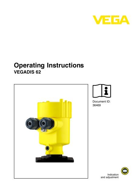
<strong>Operating</strong> <strong>Instructions</strong><strong>VEGADIS</strong> <strong>62</strong>Document ID:36469Indicationand adjustment
1 About this document1 About this document1.1 FunctionThis operating instructions manual provides all the information youneed for mounting, connection and setup as well as importantinstructions for maintenance and fault rectification. Please read thisinformation before putting the instrument into operation and keep thismanual accessible in the immediate vicinity of the device.1.2 Target groupThis operating instructions manual is directed to trained qualifiedpersonnel. The contents of this manual should be made available tothese personnel and put into practice by them.1.3 Symbolism usedInformation, tip, noteThis symbol indicates helpful additional information.Caution: If this warning is ignored, faults or malfunctions canresult.Warning: If this warning is ignored, injury to persons and/or seriousdamage to the instrument can result.Danger: If this warning is ignored, serious injury to persons and/ordestruction of the instrument can result.Ex applicationsThis symbol indicates special instructions for Ex applications.làListThe dot set in front indicates a list with no implied sequence.ActionThis arrow indicates a single action.1 SequenceNumbers set in front indicate successive steps in a procedure.4 <strong>VEGADIS</strong> <strong>62</strong>36469-EN-100514
2 For your safety2 For your safety2.1 Authorised personnelAll operations described in this operating instructions manual must becarried out only by trained specialist personnel authorised by the plantoperator.During work on and with the device the required personal protectiveequipment must always be worn.2.2 Appropriate useThe <strong>VEGADIS</strong> <strong>62</strong> is an indicating and adjustmnt unit without externalenergy for looping into 4 … 20 mA/HART circuits.You can find detailed information on the application range in chapter"Product description".Operational reliability is ensured only if the instrument is properly usedaccording to the specifications in the operating instructions manual aswell as possible supplementary instructions.2.3 Warning about misuseInappropriate or incorrect use of the instrument can give rise toapplication-specific hazards, e.g. vessel overfill or damage to systemcomponents through incorrect mounting or adjustment.2.4 General safety instructionsThis is a state-of-the-art instrument complying with all prevailingregulations and guidelines. The instrument must only be operated in atechnically flawless and reliable condition. The operator is responsiblefor the trouble-free operation of the instrument.During the entire duration of use, the user is obliged to determine thecompliance of the required occupational safety measures with thecurrent valid rules and regulations and also take note of newregulations.The safety instructions in this operating instructions manual, thenational installation standards as well as the valid safety regulationsand accident prevention rules must be observed by the user.36469-EN-100514For safety and warranty reasons, any invasive work on the devicebeyond that described in the operating instructions manual may becarried out only by personnel authorised by the manufacturer. Arbitraryconversions or modifications are explicitly forbidden.The safety approval markings and safety tips on the device must alsobe observed.<strong>VEGADIS</strong> <strong>62</strong> 5
2 For your safety2.5 CE conformityThe device fulfills the legal requirements of the applicable ECguidelines. By attaching the CE mark, VEGA provides a confirmationof successful testing. You can find the CE conformity declaration in thedownload area of www.vega.com.2.6 Fulfillment of NAMUR recommendationsThe device fulfils the requirements of the concerned NAMURrecommendation. You can find detailed information in the downloadsection under www.vega.com.2.7 Environmental instructionsProtection of the environment is one of our most important duties. Thatis why we have introduced an environment management system withthe goal of continuously improving company environmental protection.The environment management system is certified according to DINEN ISO 14001.Please help us fulfil this obligation by observing the environmentalinstructions in this manual:l Chapter "Packaging, transport and storage"l Chapter "Disposal"6 <strong>VEGADIS</strong> <strong>62</strong>36469-EN-100514
3 Product description3 Product description3.1 StructureConstituent partsType labelThe <strong>VEGADIS</strong> <strong>62</strong> consists of a housing with an integrated indicatingand adjustment module as well as a terminal insert with two terminalblocks. Another constituent part of the housing is the mounting adapterfor wall, carrier rail or tube mounting.The type label on the housing contains the most important data foridentification and use of the instrument:12345876Serial numberScope of deliveryFig. 1: Configuration of the type label1 Instrument type2 Product code3 Voltage supply/Signal output4 Protection rating5 Ambient temperature6 Order number7 Serial number of the instrument8 Document IDThe serial number on the type label of the instrument allows you tohave the order data, operating instructions manuals, sensor data forthe service DTM as well as the test certificate (depending on theinstrument) displayed via www.vega.com, "VEGA Tools" and "serialnumber search".The scope of delivery encompasses:36469-EN-100514l Indicating and adjustment unitl Documentation- this operating instructions manual- Ex-specific "Safety instructions" (with Ex versions)- if necessary, further certificates<strong>VEGADIS</strong> <strong>62</strong> 7
3 Product description3.2 Principle of operationApplication areaThe <strong>VEGADIS</strong> <strong>62</strong> is an external indicating and adjustment unit withoutexternal energy for 4 … 20 mA/HART sensors. The instrument is usedfor remote measured value indication and adjustment. It is looped inany position directly into the signal cable.Fig. 2: Connection of <strong>VEGADIS</strong> <strong>62</strong> to the sensorModesBasc mode: when used in a 4 … 20 mA signal cable, the <strong>VEGADIS</strong><strong>62</strong> operates as a pure indicating instrument. It measues the current inthe current loop and displays it as digital value as well as via bargraph.All settings of <strong>VEGADIS</strong> <strong>62</strong> are carried out manually by means of thekeys in the front. It is pure manually configured operation.HART standard: when used with a 4 … 20 mA/HART sensor, the<strong>VEGADIS</strong> <strong>62</strong> operates as automatic indicating and HART adjustmentinstrument. The <strong>VEGADIS</strong> <strong>62</strong> powered via the current loop listenscontinuously to the HART communication of the control system withthe sensor. Changes of unit and/or measuring range are adaptedautomatically.The parameter adjustment of the sensor is carried out via HARTcommunication. During the parameter adjustment, the <strong>VEGADIS</strong> <strong>62</strong>operates as Secondary Master against the sensor. With VEGAsensors, the function volume described in chapter "Parameteradjustment" is available. For sensors from other manufacturers, thefunction volume is restricted to the functions zero, span and damping.8 <strong>VEGADIS</strong> <strong>62</strong>36469-EN-100514
3 Product descriptionHART multidrop: The <strong>VEGADIS</strong> <strong>62</strong> can also be used as indicator fora bus participant on a HART multidrop system. For this purpose, it islooped into the bus and the address of the participant is set in the<strong>VEGADIS</strong> <strong>62</strong>. The instrument reads out the measured values with unitvia the HART signal and displays them.3.3 Packaging, transport and storagePackagingTransportTransport inspectionYour instrument was protected by packaging during transport. Itscapacity to handle normal loads during transport is assured by a testaccording to DIN EN 24180.The packaging of standard instruments consists of environmentfriendly,recyclable cardboard. For special versions, PE foam or PE foilis also used. Dispose of the packaging material via specialisedrecycling companies.Transport must be carried out under consideration of the notes on thetransport packaging. Nonobservance of these instructions can causedamage to the device.The delivery must be checked for completeness and possible transitdamage immediately at receipt. Ascertained transit damage orconcealed defects must be appropriately dealt with.StorageStorage and transporttemperatureUp to the time of installation, the packages must be left closed andstored according to the orientation and storage markings on theoutside.Unless otherwise indicated, the packages must be stored only underthe following conditions:l Not in the openl Dry and dust freel Not exposed to corrosive medial Protected against solar radiationl Avoiding mechanical shock and vibrationl Storage and transport temperature see chapter "Supplement -Technical data - Ambient conditions"l Relative humidity 20 … 85 %36469-EN-100514<strong>VEGADIS</strong> <strong>62</strong> 9
4 Mounting4 Mounting4.1 General instructionsMoistureUse the recommended cables (see chapter "Connecting to powersupply") and tighten the cable gland.You can give your instrument additional protection against moisturepenetration by leading the connection cable downward in front of thecable entry. Rain and condensation water can thus drain off. Thisapplies mainly to outdoor mounting as well as installation in areaswhere high humidity is expected (e.g. through cleaning processes) oron cooled or heated vessels.4.2 Mounting instructionsWall mounting<strong>VEGADIS</strong> <strong>62</strong> for wall mounting is supplied with a mounting socket.12 mm(0.47")7 mm(0.28")<strong>62</strong> mm(2.44")85 mm (3.35")Fig. 3: <strong>VEGADIS</strong> <strong>62</strong> for wall mounting, bottom view of mounting plate.1 Drilling dimensionsCarrier rail mounting<strong>VEGADIS</strong> <strong>62</strong> for mounting on carrier rail is supplied with a mountingadapter.1 2 3Fig. 4: <strong>VEGADIS</strong> <strong>62</strong> for carrier rail mounting1 Adapter plate2 Screw M4 x 63 Carrier rail10 <strong>VEGADIS</strong> <strong>62</strong>36469-EN-100514
4 MountingTube mounting<strong>VEGADIS</strong> <strong>62</strong> for tube mounting is supplied with a meas. instrumentholder and four screws M5 x 12 as mounting accessory. The meas.instrument holder is mounted to the socket of <strong>VEGADIS</strong> <strong>62</strong>.312Fig. 5: <strong>VEGADIS</strong> <strong>62</strong> for tube mounting1 4 screws M5 x 122 Measuring instrument holder3 Tube36469-EN-100514<strong>VEGADIS</strong> <strong>62</strong> 11
5 Connecting to power supply5 Connecting to power supply5.1 Preparing the connectionSafety instructionsAlways keep in mind the following safety instructions:l Connect only in the complete absence of line voltagel If overvoltages are expected, install overvoltage arrestersVoltage supplyPower supply and current signal are carried on the same two-wirecable. The voltage supply range can differ depending on the sensor.The data for power supply are specified in chapter "Technical data".Provide a reliable separation between the supply circuit and the mainscircuits according to DIN VDE 0106 part 101.Keep in mind the following additional influences on the operatingvoltage:l Output voltage of the power supply unit can be lower undernominal load (with a sensor current of 20.5 mA or 22 mA in case offault message)l Influence of additional instruments in the circuit (see load values inchapter "Technical data")Operation of <strong>VEGADIS</strong> <strong>62</strong> in a HART multidrop system with the signalconditioning instruments VEGAMET <strong>62</strong>5 or VEGASCAN 693 is notsupported.Connection cableThe instrument is connected with standard two-wire cable withoutscreen. If electromagnetic interference is expected which is above thetest values of EN 61326 for industrial areas, screened cable should beused.Use cable with round cross-section. A cable outer diameter of 5 … 9 mm(0.2 … 0.35 in) ensures the seal effect of the cable gland. If you areusing cable with a different diameter or cross-section, exchange theseal or use a suitable cable gland.We generally recommend the use of screened cable for HARTmultidrop mode.Cable gland ½ NPTWith plastic housing, the NPT cable gland or the Conduit steel tubemust be screwed without grease into the threaded insert.Max. torque for all housings see chapter "Technical data"12 <strong>VEGADIS</strong> <strong>62</strong>36469-EN-100514
5 Connecting to power supplyCable screening andgroundingIf screened cable is necessary, connect the cable screen on both endsto ground potential. In the sensor, the screen must be connecteddirectly to the internal ground terminal. The ground terminal on theoutside of the housing must be connected to the potential equalisation(low impedance).If potential equalisation currents are expected, the connection on theprocessing side must be made via a ceramic capacitor (e. g. 1 nF,1500 V). The low frequency potential equalisation currents are thussuppressed, but the protective effect against high frequency interferencesignals remains.Warning:Within galvanic plants as well as vessels with cathodic corrosionprotection there are considerable potential differences. Considerablyequalisation currents can be caused via the cable scrren when thescreen is earthed on both ends. To avoid this, the cable screen mustonly connected to ground potential on one side of the switchingcabinet in such applications. The cable screen must not be connectedto the internal ground terminal in the sensor and the outer groundterminal on the housing not to the potential equalisation!Information:The metal parts of the instrument (antenna, transmitter, concentrictube, etc.) are conductive connected with the inner and outer groundterminal on the housing. This connection exists either directly metallicor with instruments with external electronics via the screen of thespecial connection cable. You can find specifications to the potentialconnections within the instrument in chapter "Technical data".5.2 Connection technology and stepsConnection technologyConnection procedureThe connection of the signal cable is carried out via spring-loadedterminals in the housing.The indicating and adjustment module is connected via a cable withcoupling to the housing.Proceed as follows:1 Unscrew the housing cover36469-EN-100514<strong>VEGADIS</strong> <strong>62</strong> 13
5 Connecting to power supply2 Remove the indicating and adjustment module by turning it slightlyto the leftFig. 6: Dismounting of the indicating and adjustment module3 Loosen compression nut of the cable glands4 Remove approx. 10 cm (4 in) of the signal cable mantle, stripapprox. 1 cm (0.4 in) insulation from the ends of the individualwires14 <strong>VEGADIS</strong> <strong>62</strong>36469-EN-100514
5 Connecting to power supply5 Insert the cable into the sensor through the cable entryFig. 7: Connection steps 5 and 66 Insert the wire ends into the terminals according to the wiring planNote:Solid cores as well as flexible cores with cable end sleeves areinserted directly into the terminal openings. In case of flexible coreswithout end sleeves, press the terminal with a small screwdriver; theterminal opening is freed. When the screwdriver is released, theterminal closes again.7 Check the hold of the wires in the terminals by lightly pulling onthem8 Connect the screen to the internal ground terminal, connect theouter ground terminal to potential equalisation9 Attach the indicating and adjustment module again and turn itslightly to the right10 Tighten the compression nut of the cable glands. The seal ringmust completely encircle the cable11 Screw the housing cover onThe electrical connection is finished.36469-EN-100514Note:The terminal block is pluggable and can be removed from theelectronics. For this purpose, lift the terminal block with a smallscrewdriver and pull it out. When inserting the terminal block again,you should hear it snap in.<strong>VEGADIS</strong> <strong>62</strong> 15
5 Connecting to power supply5.3 Wiring plan3( + ) 1 2(-) ( + ) 3 4(-)1 2Fig. 8: Wiring plan <strong>VEGADIS</strong> <strong>62</strong>1 To the sensor2 For power supply3 Coupling for the connection cable to the indicating and adjustment module5.4 Installation HART standardThe following illustrations show in a simplified way the use of<strong>VEGADIS</strong> <strong>62</strong> in conjunction with a HART sensor. The HARTcommunication resistance in the signal cable is always required for alow impedance power supply. It is absolutely necessary to install itbetween voltage supply and the <strong>VEGADIS</strong> <strong>62</strong>.Note:If the instrument is powered via a VEGAMET signal conditioninginstrument, then the communication resistor is already included in thesignal conditioning instrument. A communication resistor in the signalcable must not be installed.Overview=~1234Fig. 9: <strong>VEGADIS</strong> <strong>62</strong> in conjunction with an individual sensor1 Sensor2 <strong>VEGADIS</strong> <strong>62</strong>3 HART resistor > 150 Ω (with low impedance power supply necessary)4 Voltage supply/Processing16 <strong>VEGADIS</strong> <strong>62</strong>36469-EN-100514
5 Connecting to power supplyConnection with low impedancepower supply1( + ) 1 2( + ) (-) 3 4(-)234Fig. 10: Connection of <strong>VEGADIS</strong> <strong>62</strong> with low impedance power supply1 Sensor2 <strong>VEGADIS</strong> <strong>62</strong>3 HART resistor > 150 Ω4 Voltage supply/Processing5.5 Installation HART multidropThe following illustrations show in a simplified way the use of<strong>VEGADIS</strong> <strong>62</strong> in conjunction with a HART sensor. The HARTcommunication resistance in the signal cable is always required for alow impedance power supply. It is absolutely necessary to install itbetween voltage supply and the <strong>VEGADIS</strong> <strong>62</strong>.Note:If the instrument is powered via a VEGAMET signal conditioninginstrument, then the communication resistor is already included in thesignal conditioning instrument. A communication resistor in the signalcable must not be installed.36469-EN-100514<strong>VEGADIS</strong> <strong>62</strong> 17
5 Connecting to power supplyOverview=~1234Fig. 11: Installation example with one <strong>VEGADIS</strong> <strong>62</strong> per sensor in a Multidropsystem1 Sensor2 <strong>VEGADIS</strong> <strong>62</strong>3 HART resistor > 150 Ω (with low impedance power supply necessary)4 Voltage supply/Processing123=4~Fig. 12: Installation example with one <strong>VEGADIS</strong> <strong>62</strong> for several sensors in aMultidrop system1 Sensor2 <strong>VEGADIS</strong> <strong>62</strong>3 HART resistor > 150 Ω (with low impedance power supply necessary)4 Voltage supply/Processing18 <strong>VEGADIS</strong> <strong>62</strong>36469-EN-100514
5 Connecting to power supplyConnection with low impedancepower supply1( + ) 1 2( + ) (-) 3 4(-)234Fig. 13: Connection of <strong>VEGADIS</strong> <strong>62</strong> with low impedance power supply1 Sensor2 <strong>VEGADIS</strong> <strong>62</strong>3 HART resistor > 150 Ω4 Voltage supply/Processing5.6 Switch on phaseDuring the start-up process, the <strong>VEGADIS</strong> <strong>62</strong> tries automatically to getin contact with the connected HART sensor and to accept the settings(unit, damping and adjustment) of this sensor. During connection, thestatus line displays "No HART".If a HART sensor is identified, then the HART symbol is displayed. The<strong>VEGADIS</strong> <strong>62</strong> switches to HART mode and and starts operation withthe settings accepted from the sensor.This procedure is repeated whenever the voltage supply is connected.If during the start process an individual key is pressure or if theinstrument has not identified within approx. 70 seconds a HARTsensor, then the digital indication switches to basic mode and startsoperation with the default settings.If the HART address is modified during operation, a new connection isestablished, however, the sensor must answer immediately so that theconnection can be realised.36469-EN-100514<strong>VEGADIS</strong> <strong>62</strong> 19
6 Set up6 Set up6.1 Adjustment system12345Fig. 14: Indicating and adjustment elements1 Status information (HART mode, unit lock, warning or error information)2 Unit and information line3 Digital measured value indication4 Bar graph for quasianalogue measured value indication5 Adjustment keysKey functionsYou adjust <strong>VEGADIS</strong> <strong>62</strong> via the four front keys. The individual menuitems are displayed on the LC display. The individual keys have thefollowing functions:l [↑] key:- One menu item upward in the menu system- Increase actual value (increment)l [ESC] key:- interrupt input- jump to the next higher menul [OK] key:- Move to the menu overview- Confirm selected menu- Edit parameter- Save valuel [↓] key:- One menu item downward in the menu system- Reduce actual value (decrement)Approx. 10 minutes after the last pressing of a key, an automatic resetto measured value indication is triggered. Any values not confirmedwith [OK] will not be saved.20 <strong>VEGADIS</strong> <strong>62</strong>36469-EN-100514
6 Set upStart parameter adjustmentEdit valuesBy pushng the [OK] key, the parameter adjustment mode will bestarted. The parameter adjustment is carried out via an adjustmentmenu. The same menu window is opened from which the parameteradjustment mode is quit during the last parameter adjustment. Singlepoints in the menu can be selected with the [↑] and [↓] keys. Thebranching to the next submenu is carried out by pushing the [OK] keyagain.In a submenu you change with [OK] to the editing function, this meansthe displayed settings can be changed. If the indication is in the editingmode, then the edited value flashes. Editing is carried out with the [↑]and [↓] keys.In the editing mode, you jump to the range end when you hold the [↑]or [↓] key by pushing [ESC]. by pushing [OK] you jump to the rangestart. When holding the [↑] keyand by pushing the [↓] key (and viceversa), then the value zero is adjusted, When increasing a value at theend of the adjustment range, you jump to the range start and viceversa.The editing function and be quit with [ESC] (without accepting themodifications) and with [OK] (accepting the modifications).6.2 Mode HART standardThe <strong>VEGADIS</strong> <strong>62</strong> monitors the current loop constantly duringoperation for a HART communication between control system andsensor. In case of changes of unit or adjustment of the connectedsensor by the control system, the unit and the corresponding indicatingrange are automatically adapted in <strong>VEGADIS</strong> <strong>62</strong>. The prerequisitehowever is that the unit set in the sensor must be stored in <strong>VEGADIS</strong><strong>62</strong>.There is no automatic changeover of the digital indication if the unit"USER" is used.Note:The <strong>VEGADIS</strong> <strong>62</strong> reacts only to standard HART commands 15 and 35.If a connected HART sensor is configured via other commands, theautomatic setting of the insturment is not possible! The applies tosettings carried out on the sensor via other adjustment units such asfor example an indicating and adjustment module or PACTware.The <strong>VEGADIS</strong> <strong>62</strong> enables also that measuring range and unit of theconnected HART sensor can be modified. For doing this, no additionalinstruments or devices are necessary. Further changes on theconfiguration of the sensor cannot be carried out.36469-EN-100514The displays shows a flashing heart symbol as long as a HARTcommunication takes place for the first time and the digital indicaton ishence set in the HART mode (safe mode). The heart symbol ispermanently displayed if the HART communication is finished and the<strong>VEGADIS</strong> <strong>62</strong> 21
6 Set updigital indication is configured according to the measuring range andthe unit of the connected sensor. After interrupting the power supply orif the digital indication was set manually, then the heart symbolextinguishes.As long as a HART communication takes place from the control room,then the heart symbol flashes in the display.The heart symbol is not displayed during operation in basic mode.6.3 HART multidrop modeOperation of the <strong>VEGADIS</strong> <strong>62</strong> in Multidrop mode is possible. In thisspecially defined operating status for HART sensors, the current signalis fixed at 4 mA and the measurement information is only transmittedvia HART communication to the control room. To enable the indicationof the measured value of a transmitter, the address of the requestedtransmitter must be set in the menu item "Adresse".The <strong>VEGADIS</strong> <strong>62</strong> shows the measured values of the primary variabletransmitted via HART to the control system. The display reactspassive, this means that the transmission of the measured values mustbe requested by the control system.6.4 Parameter adjustmentWith the parameter adjustment, the instrument is adapted to theapplication conditions. The parameter adjustment is carried out via anadjustment menu.The main menu is divided into three areas with the following functions:Measurement: Contains for example unit, measuring range, liveadjustment, damping, HART addressIndication: Contains for example unit, unit locking, display format,filter, alarms min./max. storageConfiguration: Contains for example language, contrast, reset, userunit, min./max. failure message, firmware versionMeasurement/UnitMenu section measurementAdjustment of the unit of the measuring range of the connectedtransmitterl Electrical measured variable: V, mA, Ohml Pressure: bar, mbar, PSI, hPa, kPa, mmH2O, mH2O, inHG22 <strong>VEGADIS</strong> <strong>62</strong>36469-EN-100514
6 Set upl Temperature: °C, °F, Kl Others: %In addition to the fixed stored units, also the unit "USER" can beprogrammed individually by the user (see "Configuration/USER unit").Measurement/Measuringrange beginAdjustment of the beginning value of the measuring range of theconnected sensor (for example 0 bar with a measuring range of-1 … 5 bar). The measuring range beginning value is first of all takenon by the sensor when starting with connected sensor. The measuringrange beginning value of the sensor can then be modified here.This is a min. adjustment to which 0 % of the current output areassigned. The value entered here does not change the measuringrange end value.Adjustment range: -9999 … 99999Measurement/Measuringrange endAdjustment of the end value of the measuring range of the connectedtransmitter (for example 4 bar with a measuring range of -1 … 5 bar).The measuring range end value is first of all taken on by the sensorwhen starting with connected sensor. The measuring range end valueof the sensor can then be changed here.This is a max. adjustment to which 100 % of the current output isassigned. The value entered here does not change the measuringrange beginning value.Adjustment range: -9999 … 9999936469-EN-100514<strong>VEGADIS</strong> <strong>62</strong> 23
6 Set upMeasurement/Measuringrange decimal pointAdjustment of the decimal point for the measuring range of theconnected transmitter.Adjustment range: 0, 0.0, 0.00, 0.000, 0.0000Measurement/Live adjustmentspanIn this menu item, the actual measured value is accepted as spansetting for the sensor.This is a span adjustment to which 100 % of the current output areassigned. The value accepted here, does not change the zero point.Live adjustment span is only active if a transmitter is connected whichdoes support HART.Measurement/Live adjustmentzero pointIn this menu item, the actual measured value is accepted as min.setting for the sensor.This is a zero adjustment to which 0 % of the current output areassigned. The value accepted hier, shifts the measuring range end!The difference between measuring range begin and end howeverremains.Live adjustment zero point is not active if a transmitter is connectedwhich does not support HART.Measurement/DampingIn this menu item, the integration time for damping the measured valueis entered.Adjustment range: 0.0 … 999 s24 <strong>VEGADIS</strong> <strong>62</strong>36469-EN-100514
6 Set upMeasurement/AddressAdjustment of the HART address of the assigned transmitter inMultidrop mode. With standard current loop operation, this addressmust always be set to 0.Adjustment range: 0 … 15Indication/UnitMenu section displayAdjustment of the unit for the indication of the digital display. A unitdeviating from the unit from the measuring range of the connectedtransmitter. The measured values are automatically converted intodeviating units. However, only units from the same unit group as theselected unit of the measuring range can be selected.Adjustment range: bar, mbar, PSI, MPa, hPa, kPa, mmH2O, mH2O,mHg, °C, °F, K, V, Ohm, USER36469-EN-100514Indication/Unit lockingBy activating the unit locking, the adjusted indicating unit will be lockedagainst modifications, the display shows "GESP/LoC". Modifications ofthe measuring range are converted automatically. The unit lockingfunctions only if the units from measuring range and indication are fromthe same unit group.When connecting a transmitter and its configuration via HART with aunit from another unit group, then the unit locking will be deactivated.For this purpose, the indicating unit is adjusted according to theconfigured measuring range unit.Adjustment range:l nGESP/UnLoC<strong>VEGADIS</strong> <strong>62</strong> 25
6 Set upl GESP/LoCIndication/Indication decimalpointAdjustment of the decimal point for the indication area of the digitalindicationAdjustment range: 0, 0.0, 0.00, 0.000, 0.0000l nGESP/UnLoCl GESP or LoCIndication/Digital filterActivation of the digital filter 1. order.Adjustment range: 0 … 10Indication/AlarmFrom this menu item you jump to the alarm configuration by pushingOK.Indication/Alarm On/OffSwitching on or switching off the alarm function. If an adjusted alarmlimit is exceeded or decreased, the warning symbol is displayed in theindication and the measured value begins to flash.Adjustment range: Off/On26 <strong>VEGADIS</strong> <strong>62</strong>36469-EN-100514
6 Set upIndication/Min. alarmAdjustment of the value that triggers the alarm function if underrun.Adjustment range: Initial value of the indicating range up to theadjusted value of the max. alarmIndication/Max. alarmAdjustment of the value that triggers the alarm function if exceeded.Adjustment range: adjusted value of the min. alarm up to the final valueof the indicating range.Indication/Min./Max. storageFrom this menu item you jump to the min./max. value storage bypushing "[OK]".Adjustment range: adjusted value of the min. alarm up to the final valueof the indicating range.36469-EN-100514Indication/Delete min./max.Function to delete the max. value memory. By pushing the OK keytwice, the max. value memories will be deleted.<strong>VEGADIS</strong> <strong>62</strong> 27
6 Set upIndication/Min. value,max. valueActivation of the min./max. value indication. If the min./max. valueindication is switched on, the indication switches over cyclicallybetween the actual measured value (indication period 5 s), the min.value and the max. value (indication period each 2 s). With thepresentation of the max. values the displayed unit is replaced by themin. or max. value.Adjustment range: On, OffConfiguration/LanguageMenu section configurationLanguage settingAdjustment range: dEU (German), EnG (English)Configuration/ContrastAdjustment of the display contrastAdjustment range: 0 … 428 <strong>VEGADIS</strong> <strong>62</strong>36469-EN-100514
6 Set upConfiguration/ResetIn a reset, all settings of the digital indication are reset to default. Toactivate the reset, the "SELECT" key must be pressed 2 times. Afterthe key is pressed once, the indication "RESET" begins to flash, afterthe key is pressed a second time, the indication is faded outcompletely and the reset is carried out.The following table shows the default values:Menu section Menu item Default valueMeasurement Unit ??? (if no HART adjustment wascarried out)Measuring rangebeginMeasuring rangeendMeasuring rangedecimal point4.00020.0000.000Damping 2Address 0Indication Unit mAUnit lockingIndication rangedecimal pointnGESP0.000Filter 0Alarm -Alarm On/OffOffMin. alarm 4.000Max. alarm 20.000Min./Max. valuememoryDelete min./max.-dEL36469-EN-100514Min./Max. On/Off OffConfiguration Language EnGContrast 2<strong>VEGADIS</strong> <strong>62</strong> 29
6 Set upMenu section Menu item Default valueReset -USER unitMin. failure messageMax. failure messageUSER3.<strong>62</strong>1.0Configuration/USER unitA 6-digit user unit can be programmed individually by the user. The 6characters can be selected from an alphanumerical character set. Bypushing the [OK] key, the first position is selected and begins to flash.With the arrow keys, the requested character can be selected. Bypushing the [OK] key again, the character is confirmed and switchedover to the next position.Configuration/Min. failuremessageAdjustment of the current value that triggers the min. failure messagewhen it is reached or underrun. The min. failure message is shown inthe display with 5 underlines ( _ _ _ _ _ ) and the message "AUSMIN"(or "OUTMIN").Adjustment range: 3.5 … 3.9Configuration/Max. failuremessageAdjustment of the current value that triggers the max. failure messagewhen it is reached or exceeded. The max. failure message is shown inthe display with 5 overlines ( ¯ ¯ ¯ ¯ ¯ ) and the message "AUSMAX" (or"OUTMAX").Adjustment range: 20.1 … 21.530 <strong>VEGADIS</strong> <strong>62</strong>36469-EN-100514
6 Set upConfiguration/FirmwareThe number of the firmware used is displayed.36469-EN-100514<strong>VEGADIS</strong> <strong>62</strong> 31
7 Diagnosis and service7 Diagnosis and service7.1 MaintenanceWhen the device is used correctly, no maintenance is required innormal operation.7.2 Error messagesHART communication errors are signalled with numerical codes 1 - 9.An error message is carried out if a transaction was not successfulafter multiple repetition.An error message is only displayed if an error occurs due to atransmitted command, this means only if the error is caused by anadjustment of the user. Errors in the communication between controlsystem and sensor are detected but not displayed.The measured value line shows "Error“, the status line "HART n“whereby "n" represents the numerical error code. The error messageis displayed up to the next key pressing.The following table shows the error codes and gives information on thefailure reason and removal.Error code Description Cause1 Transmitter does not answer2 Communication error l Parity, checksum, packagelength faulty during receptionl Transmitter signals receipterror3 Command not implemented Command is not supported bythe transmitter.4 Range error l Value not within the rangesupported by the sensorl Requested measuring unitis not supported5 Error of the transmitter is notspecified in detailSensor signals an error in thestatus byte which was notitemized.Reaction when malfunctionsoccur7.3 Rectify malfunctionsThe operator of the system is responsible for taking suitable measuresto remove interferences.32 <strong>VEGADIS</strong> <strong>62</strong>36469-EN-100514
7 Diagnosis and serviceChecking the 4 … 20 mAsignalConnect a handmultimeter in the suitable measuring range accordingto the wiring plan. The following table describes possible errors in thecurrent signal and helps to remove them:Error Cause Removal4 … 20 mA signalnot stable4 … 20 mA signalmissingLevel fluctuationsElectrical connectionfaultyVoltage supplymissing<strong>Operating</strong> voltagetoo low or loadresistance toohighSet damping via the indicating andadjustment moduleCheck connection according to chapter"Connection steps" and if necessary,correct according to chapter"Wiring plan"Check cables for breaks; repair ifnecessaryCheck, adapt if necessaryCurrent signalgreaterthan 22 mAor less than3.6 mAOscillator in thesensor defectiveExchange the instrument or send it infor repairReaction after fault rectificationDepending on the failure reason and measures taken, the stepsdescribed in chapter "Set up" must be carried out again, if necessary.24 hour service hotlineHowever, should these measures not be successful, call the VEGAservice hotline in urgent cases under the phone no. +49 1805 858550.The hotline is available to you 7 days a week round-the-clock. Sincewe offer this service world-wide, the support is only available in theEnglish language. The service is free of charge, only the standardtelephone costs will be charged.7.4 How to proceed in case of repairIf a repair is necessary, please proceed as follows:You can download a return form (23 KB) from our Internet homepagewww.vega.com under: "Downloads - Forms and certificates - Repairform".36469-EN-100514By doing this you help us carry out the repair quickly and withouthaving to call back for needed information.l Print and fill out one form per instrumentl Clean the instrument and pack it damage-proofl Attach the completed form and, if need be, also a safety datasheet outside on the packaging<strong>VEGADIS</strong> <strong>62</strong> 33
7 Diagnosis and servicel Please ask the agency serving you for the address of your returnshipment. You can find the competent agency on our websitewww.vega.com.34 <strong>VEGADIS</strong> <strong>62</strong>36469-EN-100514
8 Dismounting8 Dismounting8.1 Dismounting stepsWarning:Before dismounting, be aware of dangerous process conditions suchas e.g. pressure in the vessel, high temperatures, corrosive or toxicproducts etc.Take note of chapters "Mounting" and "Connecting to power supply"and carry out the listed steps in reverse order.8.2 DisposalThe instrument consists of materials which can be recycled byspecialised recycling companies. We use recyclable materials andhave designed the electronics to be easily separable.WEEE directive 2002/96/EGThis instrument is not subject to the WEEE directive 2002/96/EG andthe respective national laws. Pass the instrument directly on to aspecialised recycling company and do not use the municipal collectingpoints. These may be used only for privately used products accordingto the WEEE directive.Correct disposal avoids negative effects to persons and environmentand ensures recycling of useful raw materials.Materials: see chapter "Technical data"If you have no way to dispose of the old instrument properly, pleasecontact us concerning return and disposal.36469-EN-100514<strong>VEGADIS</strong> <strong>62</strong> 35
9 Supplement9 Supplement9.1 Technical dataGeneral data316L corresponds to 1.4404 or 1.4435, 316Ti corresponds to 1.4571Materials- Housing plastic PBT, Alu die-casting, 316L- Inspection window in housing cover forindicating and adjustment module- Ground terminal 316Ti/316LPolycarbonate (UL-746-C listed)Weight0.35 kg (0.772 lbs)Supply circuitVoltage supply and data transmissionvia the signal circuitVoltage loss- at 4 mA approx. 3 V- at 20 mA approx. 2 VCurrent range 3.5 … 22.5 mA 1)Current increase with command/enquiry ofthe <strong>VEGADIS</strong> <strong>62</strong> to the sensorOvercurrent resistanceInterpolation protectionCurrent measurement≤ 500 µA for approximately 20 ms, decay after e-function100 mAavailable, max. current 100 mAMeasuring range loop current 3.5 … 22.5 mA 2)Deviation 3)Temperature coefficient 4)IntervalIndicating and adjustment module±0.05 % of the span±0.1 % of the span/10 K250 msDisplay- Principle LCD- Measured value presentation 7 segments, 5-digit, height of digits 9 mm (0.354 in),indication range -99999 … 99999- Bar graph 20 segments- Info line 14 segments, 6-digit, height of digits 5.5 mm(0.217 in)1)The indication remains dark if the loop current is not sufficient for operation.2)For measured values outside the measuring range, an instructions is displayedinstead of the measured value.3)with reference temperature 20 °C4)with reference temperature 20 °C36 <strong>VEGADIS</strong> <strong>62</strong>36469-EN-100514
9 SupplementAdjustment elements4 keysProtection rating- unassembled IP 20- mounted into <strong>VEGADIS</strong> <strong>62</strong> without cover IP 40Materials- Housing ABS- Inspection window Polyester foilAmbient conditionsAmbient temperatureStorage and transport temperature-20 … +70 °C (-4 … +158 °F)-40 … +80 °C (-40 … +176 °F)Electromechanical dataCable gland2 x cable entry M20 x 1.5 (cable: ø 5 … 9 mm)Spring-loaded terminals for wire cross-section- Massive wire, cord 0.2 … 2.5 mm² (AWG 24 … 14)- Cord with cable end sleeve 0.2 … 1.5 mm² (AWG 24 … 16)Electrical protective measuresProtection rating- Housing plastic IP 66/IP 67- Housing Aluminium, stainless steel IP 66/IP 68 (0.2 bar)Overvoltage categoryProtection classIIIII36469-EN-100514<strong>VEGADIS</strong> <strong>62</strong> 37
9 Supplement9.2 HART communicationThe HART protocol operates with the technology of the frequency shift keying (FSK = frequency shiftkeying) based on the data communication standard Bell 202. The digital signal is generated out of thefrequencies 1200 and 2200 Hz representing each the bit information 1 and 0. Sinus curves with thesefrequencies are superimposed to the direct current in the wire pair of the field device. The averagevalue of the superimposed signal is zero. Hence the 4 … 20 mA signal is not influenced by the digitaldata transmission.Commands when transmittingDuring transmission, only the long address format is used which is supported by all sensors as ofHART revision 5.Command no. Command name Description0 Read UID For determination of the UID from the polling address15 Read output information To update the scaling of the display after ZERO orSPAN34 Write damping value -35 Write range values Adjustment of the transmitter scaling36 Set upper range value SPAN button37 Set lower range value zero button44 Write PV units Adjustment of the transmitter unit54 Read Transmitter VariableInformationTo read out the adjusted dampingCommand during receptionOnly messages are received the return address of which correspond with adjusted polling address orthe determined UID.Command no. Command name Description1 Read primary variable To check the adjusted measuring unit3 Read current & 4 vars To check the adjusted measuring unit15 Read output information Accept transmitter scaling35 Write range values Transmitter scaling by control room38 <strong>VEGADIS</strong> <strong>62</strong>36469-EN-100514
9 Supplement9.3 Dimensions<strong>VEGADIS</strong> <strong>62</strong> housing~ 69 mm(2.72")ø 77 mm(3.03")~ 69 mm(2.72")ø 77 mm(3.03")~ 59 mm(2.32")ø 80 mm(3.15")123 mm (4.84")128 mm (5.04")112 mm (4.41")M20x1,5/½ NPTM20x1,5/½ NPTM20x1,5/½ NPT~ 116 mm (4.57")1 2 3ø 84 mm (3.31")125 mm (4.92")M20x1,5/½ NPTM20x1,54Fig. 15: <strong>VEGADIS</strong> <strong>62</strong> housing versions1 Plastic housing2 Stainless steel housing - precision casting3 Stainless steel housing, electropolished4 Aluminium housing36469-EN-100514<strong>VEGADIS</strong> <strong>62</strong> 39
9 SupplementMounting adapter <strong>VEGADIS</strong> <strong>62</strong>5mm(13/64")16mm(5/8")R32mm(1 17/ 64")M667mm (2 41/64")~ 111mm (4 31/8")3mm(1/8")11mm(7/16")60mm (2 23/ 64")1 2 370mm (2 3/ 4")84mm (3 5/ 16")Fig. 16: Mounting adapter <strong>VEGADIS</strong> <strong>62</strong>1 Mounting plate for wall mounting2 Clip for carrier rail mounting3 Strap for tube mounting40 <strong>VEGADIS</strong> <strong>62</strong>36469-EN-100514
9 Supplement9.4 Industrial property rightsVEGA product lines are global protected by industrial property rights.Further information see http://www.vega.com.Only in U.S.A.: Further information see patent label at the sensorhousing.VEGA Produktfamilien sind weltweit geschützt durch gewerblicheSchutzrechte.Nähere Informationen unter http://www.vega.com.Les lignes de produits VEGA sont globalement protégées par desdroits de propriété intellectuelle.Pour plus d'informations, on pourra se référer au site http://www.vega.com.VEGA lineas de productos están protegidas por los derechos en elcampo de la propiedad industrial.Para mayor información revise la pagina web http://www.vega.com.Линии продукции фирмы ВЕГА защищаются по всему мируправами на интеллектуальную собственность.Дальнейшую информацию смотрите на сайте http://www.vega.com.VEGA 系 列 产 品 在 全 球 享 有 知 识 产 权 保 护 。进 一 步 信 息 请 参 见 网 站 。9.5 TrademarkAll brand names as well as trade and company names used areproperty of their lawful proprietor/originator.36469-EN-100514<strong>VEGADIS</strong> <strong>62</strong> 41
IndexINDEXAAlarm configuration 26-27Application area 8CCable entry 12Check signal 33Connection cable 12Connection procedure 13Connection technology 13Contrast 28DDamping 24Decimal point indication 26Digital filter display 26EError messages 32FFailure message 30Firmware 31PPotential equalisation 13RReset 29SSerial number 7Service hotline 33Shielding 13TType label 7UUnit 22Unit digital indication 25Unit locking 25USER unit 30VVoltage supply 12GGrounding 13HHART address 25HART communication 21LLanguage 28Live adjustment span 24Live adjustment zero point 24MMeasuring range begin 23Measuring range decimal point 24Measuring range end 23Min./max. memory 27-28Modes 8Moisture 10Mounting types- Carrier rail mounting 10- Tube mounting 11- Wall mounting 1042 <strong>VEGADIS</strong> <strong>62</strong>36469-EN-100514
Index36469-EN-100514<strong>VEGADIS</strong> <strong>62</strong> 43
Printing date:VEGA Grieshaber KGAm Hohenstein 11377761 SchiltachGermanyPhone +49 7836 50-0Fax +49 7836 50-201E-mail: info@de.vega.comwww.vega.comISO 9001All statements concerning scope of delivery, application,practical use and operating conditions of the sensors andprocessing systems correspond to the information availableat the time of printing.© VEGA Grieshaber KG, Schiltach/Germany 2010Subject to change without prior notice36469-EN-100514


