High-Voltage, High-Current OPERATIONAL AMPLIFIER OPA544
High-Voltage, High-Current OPERATIONAL AMPLIFIER OPA544
High-Voltage, High-Current OPERATIONAL AMPLIFIER OPA544

You also want an ePaper? Increase the reach of your titles
YUMPU automatically turns print PDFs into web optimized ePapers that Google loves.
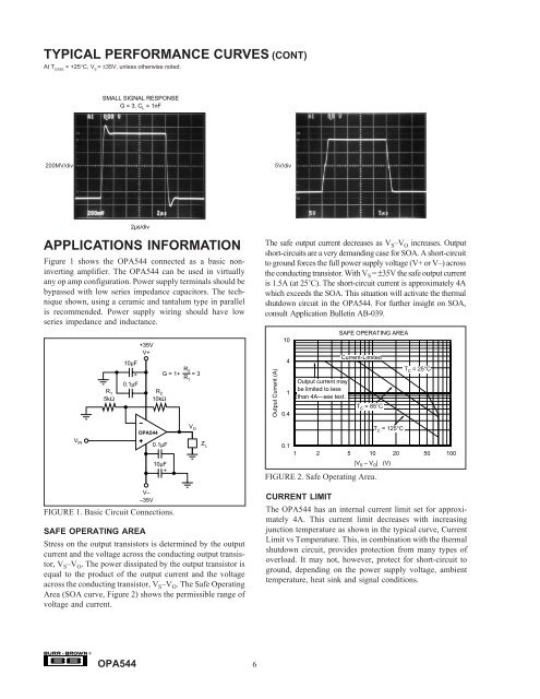
TYPICAL PERFORMANCE CURVES (CONT)At T CASE= +25°C, V S= ±35V, unless otherwise noted.SMALL SIGNAL RESPONSEG = 3, C L = 1nF200MV/div5V/divAPPLICATIONS INFORMATIONFigure 1 shows the <strong>OPA544</strong> connected as a basic noninvertingamplifier. The <strong>OPA544</strong> can be used in virtuallyany op amp configuration. Power supply terminals should bebypassed with low series impedance capacitors. The techniqueshown, using a ceramic and tantalum type in parallelis recommended. Power supply wiring should have lowseries impedance and inductance.R 15kΩ+35VV+10µF0.1µF2µs/div+R 210kΩR 2G = 1+ = 3R 1The safe output current decreases as V S –V O increases. Outputshort-circuits are a very demanding case for SOA. A short-circuitto ground forces the full power supply voltage (V+ or V–) acrossthe conducting transistor. With V S = ±35V the safe output currentis 1.5A (at 25˚C). The short-circuit current is approximately 4Awhich exceeds the SOA. This situation will activate the thermalshutdown circuit in the <strong>OPA544</strong>. For further insight on SOA,consult Application Bulletin AB-039.Output <strong>Current</strong> (A)10410.4Output current maybe limited to lessthan 4A—see text.SAFE OPERATING AREA<strong>Current</strong>-LimitedT C = 85°CT C = 25°C<strong>OPA544</strong>V OT C = 125°CV IN0.1µF10µF+Z L0.11 2 5 10|V S – V O | (V)20 50 100FIGURE 2. Safe Operating Area.V––35VFIGURE 1. Basic Circuit Connections.SAFE OPERATING AREAStress on the output transistors is determined by the outputcurrent and the voltage across the conducting output transistor,V S –V O . The power dissipated by the output transistor isequal to the product of the output current and the voltageacross the conducting transistor, V S –V O . The Safe OperatingArea (SOA curve, Figure 2) shows the permissible range ofvoltage and current.CURRENT LIMITThe <strong>OPA544</strong> has an internal current limit set for approximately4A. This current limit decreases with increasingjunction temperature as shown in the typical curve, <strong>Current</strong>Limit vs Temperature. This, in combination with the thermalshutdown circuit, provides protection from many types ofoverload. It may not, however, protect for short-circuit toground, depending on the power supply voltage, ambienttemperature, heat sink and signal conditions.®<strong>OPA544</strong>6