Operating and installation instructions KNX MSE 8M230 - Warema
Operating and installation instructions KNX MSE 8M230 - Warema
Operating and installation instructions KNX MSE 8M230 - Warema

You also want an ePaper? Increase the reach of your titles
YUMPU automatically turns print PDFs into web optimized ePapers that Google loves.
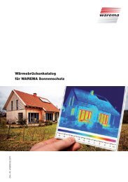
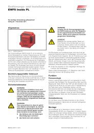
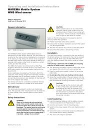
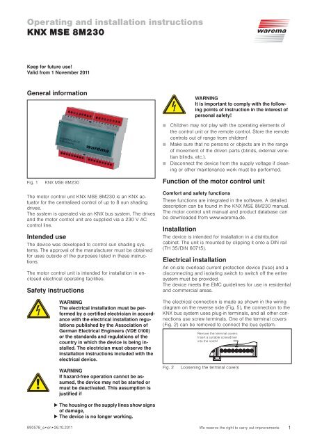
<strong>Operating</strong> <strong>and</strong> <strong>installation</strong> <strong>instructions</strong><strong>KNX</strong> <strong>MSE</strong> <strong>8M230</strong>Keep for future use!Valid from 1 November 2011General informationWARNINGIt is important to comply with the followingpoints of instruction in the interest ofpersonal safety!Fig. 1<strong>KNX</strong> <strong>MSE</strong> <strong>8M230</strong> Children may not play with the operating elements ofthe control unit or the remote control. Store the remotecontrols out of range from children! Make sure that no persons or objects are in the rangeof movement of the driven parts (blinds, external venetianblinds, etc.). Disconnect the device from the supply voltage if cleaningor other maintenance work must be performed.Function of the motor control unitThe motor control unit <strong>KNX</strong> <strong>MSE</strong> <strong>8M230</strong> is an <strong>KNX</strong> actuatorfor the centralised control of up to 8 sun shadingdrives.The system is operated via an <strong>KNX</strong> bus system. The drives<strong>and</strong> the motor control unit are supplied via a 230 V ACcontrol line.Intended useThe device was developed to control sun shading systems.The approval of the manufacturer must be obtainedfor uses outside of the purposes listed in these <strong>instructions</strong>.The motor control unit is intended for <strong>installation</strong> in enclosedelectrical operating facilities.Safety <strong>instructions</strong>WARNINGThe electrical <strong>installation</strong> must be performedby a certified electrician in accordancewith the electrical <strong>installation</strong> regulationspublished by the Association ofGerman Electrical Engineers (VDE 0100)or the st<strong>and</strong>ards <strong>and</strong> regulations of thecountry in which the device is being installed.The electrician must observe the<strong>installation</strong> <strong>instructions</strong> included with theelectrical device.Comfort <strong>and</strong> safety functionsThese functions are integrated in the software. A detaileddescription can be found in the <strong>KNX</strong> <strong>MSE</strong> <strong>8M230</strong> manual.The motor control unit manual <strong>and</strong> product database canbe downloaded from www.warema.de.InstallationThe device is intended for <strong>installation</strong> in a distributioncabinet. The unit is mounted by clipping it onto a DIN rail(TH 35/DIN 60715).Electrical <strong>installation</strong>An on-site overload current protection device (fuse) <strong>and</strong> adisconnecting <strong>and</strong> isolating switch to switch off the entiresystem must be provided.The device meets the EMC guidelines for use in residential<strong>and</strong> commercial areas.The electrical connection is made as shown in the wiringdiagram on the reverse side (Fig. 5), the connection to the<strong>KNX</strong> bus system uses plug-in terminals, <strong>and</strong> all other connectionsuse screw terminals. One of the terminal covers(Fig. 2) can be removed to connect the bus system.Remove the terminal covers:Insert a suitable screwdriverinto the notch!WARNINGIf hazard-free operation cannot be assumed,the device may not be started ormust be deactivated. This assumption isjustified ifFig. 2Loosening the terminal covers The housing or the supply lines show signsof damage, The device is no longer working.890578_a•en•26.10.2011 We reserve the right to carry out improvements 1
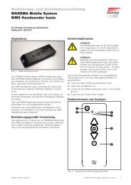
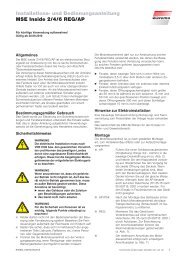
RCommissioningAfter the <strong>installation</strong> has been completed <strong>and</strong> the supplyvoltage is applied, the device can be operated on a membranekeyboard (Fig. 3).Local operationThe membrane keyboard consists of 4 buttons; the UP/DOWN <strong>and</strong> PRG buttons have an integrated LED. Thechannel is selected using the SEL (Select) button. The selectedchannel is displayed by one of the 8 channel LEDs.Fig. 3PRGSELMembrane keyboard<strong>KNX</strong> <strong>MSE</strong> <strong>8M230</strong>1234Upon delivery, all outputs can be operated in dead man'smode (jog mode, when the button is released, the respectiverelay drops out immediately).To select the channel, press the SEL (Select) button repeatedlyuntil the desired channel lights up. When the UPor DOWN button is activated, the relay begins operating<strong>and</strong> the associated output is switched accordingly for theduration of the activation.5678MaintenanceThere are no parts within the device that require maintenance.In the event of a malfunction, the built-in miniaturefuses should only be changed by a qualified electrician.LiabilityFailure to comply with the product information in these<strong>instructions</strong> <strong>and</strong> use of the unit in a manner that contravenesits intended use <strong>and</strong> purpose may result in themanufacturer refusing to honour warranty claims for productdamage. In this case, liability for consequential harmto persons or damage to property will also be excluded.Follow the <strong>instructions</strong> in the operating manual of your sunshading system. The automatic or manual operation ofthe sun shading system when iced over as well as usingthe sun shading system during severe weather may causedamage <strong>and</strong> must be prevented by the user by taking suitableprecautions.DisposalAfter its use, the device must be disposed of according tolegal regulations or returned to your local recycling centre.EIB <strong>and</strong> <strong>KNX</strong> are registered trademarks of the KONNEXAssociation.WARNINGNever r<strong>and</strong>omly press the keys on themembrane keyboard without having a lineof sight to the sun shading system.ProgrammingNOTE:Take suitable precautions to prevent damagedue to electrostatic discharge!Press the programming button (Fig. 3) to putthe device into programming mode. The redLED lights up when programming mode isactive. The device is programmed on a PCwith the corresponding software. This softwareends the programming mode automatically.The red LED goes out.If the programming mode is to be endedearlier, press the programming button again.The red LED goes out.2We reserve the right to carry out improvements890578_a•en•26.10.2011
Technical data<strong>KNX</strong> <strong>MSE</strong> <strong>8M230</strong> Min. Typ. Max. Unit<strong>Operating</strong> voltage 198 230 253 V ACQuiescent current consumption,10 13 18 mAprimaryDegree of protection inIP30DIN rail-mounted housingDegree of protectionI(PE is looped through)Output per driveSwitching capacity500 VAat 230 V AC/cos ϕ = 0.6<strong>KNX</strong> input TP 1<strong>KNX</strong> current consumption 9 mAVoltage 29 V DCConformityViewable at www.warema.deAmbient conditions<strong>Operating</strong> temperature -5 20 40 °CStorage temperature 0 20 60 °CRel. humidity10 40 85 %RH(non-condensing)ConnectionSupply line, drivesScrewed terminals<strong>KNX</strong> bus systemSpring-load terminalsWire cross sectionsSupply line, outputsMax. 2.5 mm<strong>KNX</strong> bus systemMax. 0.8 mm ∅Test st<strong>and</strong>ardsProduct st<strong>and</strong>ard:DIN EN60730-1:2005-12 +DIN EN50090-2-2:1997-06EIB/<strong>KNX</strong> System Conformance TestEMC basic st<strong>and</strong>ards: DIN EN61000-6-2:2002-08DIN EN61000-6-3:2005-06DIN EN 50366:2006-11EnclosureDegree of protectionREG housingIP30MiscellaneousAutomatic operation Type 1Software classALocation of useClean ambient conditionsArticle numbers<strong>KNX</strong> <strong>MSE</strong> <strong>8M230</strong> REG 1002 710WAREMA Renkhoff SEHans-Wilhelm-Renkhoff Strasse 2D-97828 Marktheidenfeld, GermanyFig. 4106 mm / 6 MW60 mm90 mm95 mmDimensions of DIN rail-mounted housing,6 MW (modular width)890578_a•en•26.10.2011We reserve the right to carry out improvements3
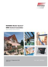
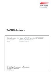
ATTENTION:Only one motor may beconnected per motor terminal set.Parallel connection will damagethe motor!M 1~12 3M 2~12 3M 3~12 3M 4~12 3all motor linesHO5RR-F 4 G 0.75 BKPower line1 2 3 1 2 3 1 2 3 1 2 3providedby customer, Lto next230 V AC N50 Hz, 16 A3 x 1.5 mmPE21 2 31 2 31 2 31 2 3components9 8 7 6N N L LX1F16.3 AT H250 V9 8 7 6 4 3 2 1M1 M2 M3 M4 X2<strong>KNX</strong> <strong>MSE</strong><strong>8M230</strong>K1 K2 K3 K4 K5 K6 K7 K8K9 K10 K11K12K13 K14 K15 K16M5 M6 M7 M81 EIB 2- +sw rtX5F26.3 AT H250 VX61 2 3 4 6 7 8 9<strong>KNX</strong>PYCYM 2x2x0.8 mm ø<strong>KNX</strong>NPE1 2 31 2 31 2 31 2 31 2 31 2 31 2 31 2 32 31M 5~2 31M 6~2 31M 7~2 31M 8~Fig. 5<strong>KNX</strong> <strong>MSE</strong> <strong>8M230</strong>4We reserve the right to carry out improvements890578_a•en•26.10.2011