Operating and installation instructions WAREMA Mobile System ...
Operating and installation instructions WAREMA Mobile System ...
Operating and installation instructions WAREMA Mobile System ...

You also want an ePaper? Increase the reach of your titles
YUMPU automatically turns print PDFs into web optimized ePapers that Google loves.
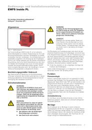
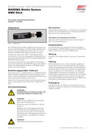
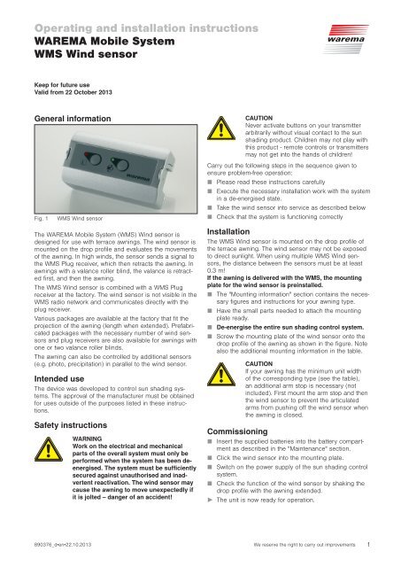
<strong>Operating</strong> <strong>and</strong> <strong>installation</strong> <strong>instructions</strong><strong>WAREMA</strong> <strong>Mobile</strong> <strong>System</strong>WMS Wind sensorKeep for future useValid from 22 October 2013General informationFig. 1WMS Wind sensorThe <strong>WAREMA</strong> <strong>Mobile</strong> <strong>System</strong> (WMS) Wind sensor isdesigned for use with terrace awnings. The wind sensor ismounted on the drop profile <strong>and</strong> evaluates the movementsof the awning. In high winds, the sensor sends a signal tothe WMS Plug receiver, which then retracts the awning. Inawnings with a valance roller blind, the valance is retractedfirst, <strong>and</strong> then the awning.The WMS Wind sensor is combined with a WMS Plugreceiver at the factory. The wind sensor is not visible in theWMS radio network <strong>and</strong> communicates directly with theplug receiver.Various packages are available at the factory that fit theprojection of the awning (length when extended). Prefabricatedpackages with the necessary number of wind sensors<strong>and</strong> plug receivers are also available for awnings withone or two valance roller blinds.The awning can also be controlled by additional sensors(e.g. photo, precipitation) in parallel to the wind sensor.Intended useThe device was developed to control sun shading systems.The approval of the manufacturer must be obtainedfor uses outside of the purposes listed in these <strong>instructions</strong>.Safety <strong>instructions</strong>WARNIN WWork on the electrical <strong>and</strong> mechanicalparts of the overall system must only beperformed when the system has been deenergised.The system must be sufficientlysecured against unauthorised <strong>and</strong> inadvertentreactivation. The wind sensor maycause the awning to move unexpectedly ifit is jolted – danger of an accident!C CAUTIONever activate buttons on your transmitterarbitrarily without visual contact to the sunshading product. Children may not play withthis product - remote controls or transmittersmay not get into the h<strong>and</strong>s of children!Carry out the following steps in the sequence given toensure problem-free operation:Please read these <strong>instructions</strong> carefullyExecute the necessary <strong>installation</strong> work with the systemin a de-energised state.Take the wind sensor into service as described belowCheck that the system is functioning correctlyInstallationThe WMS Wind sensor is mounted on the drop profile ofthe terrace awning. The wind sensor may not be exposedto direct sunlight. When using multiple WMS Wind sensors,the distance between the sensors must be at least0.3 m!If the awning is delivered with the WMS, the mountingplate for the wind sensor is preinstalled.The "Mounting information" section contains the necessaryfigures <strong>and</strong> <strong>instructions</strong> for your awning type.Have the small parts needed to attach the mountingplate ready.De-energise the entire sun shading control system.Screw the mounting plate of the wind sensor onto thedrop profile of the awning as shown in the figure. Notealso the additional mounting information in the table.C CAUTIOIf your awning has the minimum unit widthof the corresponding type (see the table),an additional arm stop is necessary (notincluded). First mount the arm stop <strong>and</strong> thenthe wind sensor to prevent the articulatedarms from pushing off the wind sensor whenthe awning is closed.CommissioningInsert the supplied batteries into the battery compartmentas described in the "Maintenance" section.Click the wind sensor into the mounting plate.Switch on the power supply of the sun shading controlsystem.Check the function of the wind sensor by shaking thedrop profile with the awning extended.The unit is now ready for operation.890376_d•en•22.10.2013 We reserve the right to carry out improvements 1
N NOTE A receiver <strong>and</strong> the connected sun shadingsystem cannot be operated until a transmitterhas been learned in successfully! The learningprocess is described in the receiver operating<strong>instructions</strong>. In addition, you can obtain the"WMS in practice" brochure with numerouspractical examples of learning, making settings<strong>and</strong> WMS networks; the brochure is availablefree of charge from your specialist dealer. Alternatively,the brochure can be downloaded at:http://www.warema.de Products Controls <strong>WAREMA</strong> <strong>Mobile</strong> <strong>System</strong>. The <strong>WAREMA</strong> <strong>Mobile</strong><strong>System</strong> also enables a wide range of specialfunctions. Should you require further information,your specialist dealer will be pleased togive you the WMS application brochure.<strong>Operating</strong> elements <strong>and</strong> displaysFig. 2 <strong>Operating</strong> panel of the WMS Wind sensorPos. Fig. FunctionA Red LTEDIndicates weak batteries, a wind alarm or a malfunctionB Learn buttonCauses the associated receiver to waveC Green LTEDIndicates that the batteries are sufficiently chargedD Battery buttonDisplays the battery charge status or activates the"Replace battery" modeBackFig. 3+ AAA –– AAA +Back of the WMS Wind sensorPos. Fig. FunctionK BatteriesThe WMS Wind sensor requires two batteries oftype AAA (IEC LR03, "Micro")OperationChecking the battery charge statusOccasionally check the battery charge status of the windsensor. If the wind sensor can no longer respond, the awningis automatically retracted or is stopped after severalseconds if it is being extended to protect against winddamage.Button/display Action/resultBriefly press the battery button.The LEDs indicate the status of the windsensor:GREEN flashes: Battery OK, communicationwith the plug receiveris OKGREEN flashes,RED lights up:RED flashes:No display:Battery OK; communicationwith the plug receiveris faultyThe battery charge statusis criticalThe battery voltage isalready below the minimumlevelOpening the "Replace battery" modeSwitch off the wind monitor as follows, for example toreplace the batteries.Button/displayAction/resultPress the battery button for at least 5 seconds.The red LED lights up.The wind monitor is deactivated. The windsensor can be removed without initiating awind alarm.N NOTE The wind sensor goes into sleepmode after 3 minutes. The "Replacebattery" mode remainsactive. It continues to remain activeeven after the batteries are replaced.Press any button to end the "Replace battery"mode.N NOTE If the "Replace battery" mode cannot be activatedbefore replacing the batteries (e.g. thebatteries are depleted), you should activate themode briefly after inserting the new batteries.In this way, the wind sensor can detect that youreplaced the batteries, enabling it to correctlydetermine the battery charge status again.Identifying the plug receiverButton/displayAction/resultPress the learn button for at least 3 seconds.The red LED lights up for half a second.The plug receiver belonging to the windsensor (i.e. the connected awning) waves.2We reserve the right to carry out improvements890376_d•en•22.10.2013
<strong>Operating</strong> the awning with a h<strong>and</strong>-heldtransmitterBefore using the remote control to operate a product:Read the operating <strong>instructions</strong> of your WMS transmitter tofamiliarise yourself with the basic operating functions.Button/displayE.g....E.g....Action/resultPress the awning button.The awning button only lights up if awningshave been learned in.The awning button flashes.In the number field, the channels on whichproducts have been learned in light up (inthe example on the left, 0 <strong>and</strong> 2). The LEDbelow the currently selected channel lightsup (in the example, channel 0).Press the flashing awning button repeatedlyuntil the LED below the desired channellights up.The LED below the selected channel lightsup (in the example, channel 2).Operate the selected awning with the UP/STOP/DOWN buttons:Awning without valance roller blind driveOperate the awning with the UP/STOP/DOWN buttons:Awning extendsAwning retractsSTOP or arrow button in the opposite direction:The movement is stopped.OIUTE The STOP button also deactivatesthe wind evaluation for oneminute. You can then extend thevalance roller blind with a h<strong>and</strong>crank, for example, without triggeringa wind alarm.Awning with valance roller blind driveOperate the awning with the UP/STOP/DOWN buttons:1 x short: Awning extendsAwning retracts2 x short: The awning extends fully,<strong>and</strong> then the valance roller blindextends fully.The valance roller blind retractsfully, <strong>and</strong> then the awningretracts fully1 x long: The valance roller blind extendsThe valance roller blindretracts. The position of the awningdoes not changeSTOP or arrow button in the opposite direction:The movement is stopped.OIUTE The STOP button also deactivatesthe wind evaluation for oneminute.Button/displayNNOTEAction/resultThe transmission LED indicates the transmissionprocess:Flashes GREEN: The h<strong>and</strong>-held transmitteris transmitting2s GREEN: The receiver confirms thecomm<strong>and</strong>2s RED: The comm<strong>and</strong> was not confirmed(e.g. the receiver isoutside of the transmissionrange)2s GREEN + control symbol is red:The receiver confirms the comm<strong>and</strong>,but does not executeit because of the displayedcontrol function (e.g. the awningis not extended becausethe wind alarm is active).If the awning is the last product you operated, youcan operate it directly using the UP/STOP/DOWN buttons or without having to wakeup the h<strong>and</strong>-held transmitter.The awning cannot be operated during a windalarm. If the wind alarm ends after 10 minutes,you can operate the awning again.In a system with two valances, the valances canonly be operated jointly. A WMS central controlunit must be used to operate them separately.Learning/recalling the comfort positionsA comfort position can be stored for each awning (e.g.awning half extended). The awning can be automaticallymoved to this comfort position at the press of a button.Button/displayAction/resultMove the awning (<strong>and</strong> the valance) to theposition that is to be stored as the comfortposition.Hold down the comfort button for 5 secondsuntil the transmission LED lights up.The transmission LED indicates the transmissionprocess:2s GREEN: The comfort position isstored2s RED: The comm<strong>and</strong> was not confirmed(e.g. the receiver isoutside of the transmissionrange); repeat the procedureTo recall a comfort position:Briefly press the comfort button.The transmission LED lights up (see above)The comfort position is restored automatically.NOTE N If the awning is already in the comfort positionor if a comfort position has not been stored,the awning does not respond to pressing of thecomfort button.After a power failure, the awning performs anautomatic calibration before moving to the comfortposition.890376_d•en•22.10.2013We reserve the right to carry out improvements3
Setting the wind speed limit(specialist dealers only)For an awning to be protected properly, the limit valueabove which a wind alarm is triggered needs to be set forthat particular awning (type, width, projection, etc.).The wind speed limit is already set to the correct valuein awnings that are delivered with the WMS.C CAUTIONever change the wind speed limit set byyour specialist dealer. An incorrect limitvalue may lead to awning damage in windyweather.Wind speed limit× 0 Wind monitoring off!1 Most sensitive setting2345 Factory setting6789 Least sensitive settingButton/Action/resultdisplayThe wind speed limit can only be changed if the WMSplug receiver was first learned into the h<strong>and</strong>-held transmitter.Using the awning button, select the channelthat you wish to set.The LED below the channel number lightsE.g.upPress the mode button with a pointedobject until lights up <strong>and</strong> mode 0 isselected.N NOTE The mode button must be pressedbefore the h<strong>and</strong>-held transmitterreturns to sleep mode.If you release the mode button tooearly or press it for too long <strong>and</strong> ahigher mode is displayed:Release the button <strong>and</strong> press <strong>and</strong>hold it again; the process restartsat 0.+ <strong>and</strong> the LED above the 0 lights up inred.Briefly press the learn button to activatethe mode.The LED above the number 0 lights upbriefly in green.The sun control is displayed automatically.Press the info button repeatedly until thesymbol for the wind control lights up.The LED below the control symbol showsthe state of the control system.GREEN: ActiveRED: InactiveE.g. The parameter value of the wind control is... displayed in the upper row of LEDs (here,E.g....limit value 2).RED:Value 0; the control function isoffGREEN: Values 1 to 9FLASHES: Multiple receivers with differentvalues in the channel. The valueof the first receiver is displayed.Use the arrow keys ( + light up) tochange the parameter value.The upper row of LEDs shows how thevalue changes (new value = 1)Press thebuttonThe transmission LED lights up for 2secondsGREEN: The parameter value was storedin all receivers of the channelRED: Not all receivers could bereached; press the buttonagain.Leave the dealer mode with the mode button( is no longer lit)4We reserve the right to carry out improvements890376_d•en•22.10.2013
Maintenance <strong>and</strong> cleaningStorageIf you will not be using the awning for an extended period(e.g. over the winter, during which negative temperatureswill shorten the battery life), take the WMS Wind sensor offthe mounting plate. Store the wind sensor in an enclosedarea <strong>and</strong> remove the batteries during this time.Replacing the batteriesCheck the battery charge status at least once a year.Replace the batteries if the red LED lights up after pressingthe battery button. If the batteries are depleted, theawning is automatically retracted or is stopped afterseveral seconds if it is being extended to protect againstwind damage.Press the battery button for approx. 5 seconds untilthe red LED lights up continuously <strong>and</strong> then take thewind sensor off the mounting plate.To replace the batteries (type AAA, IEC LR03, "Micro"),remove the four screws on back of the housing. Openthe battery compartment (Fig. 3) <strong>and</strong> insert the newbatteries. Ensure the correct polarity: The plus (+) <strong>and</strong>minus (-) poles of the batteries must agree with themarks in the battery compartment.Only use new batteries of the same type <strong>and</strong> alwaysreplace both batteries. Use high quality batteries -inexpensive batteries can leak <strong>and</strong> damage the device.If the device is not used for a longer period, please removethe batteries. Do not use rechargeable batteries.Clip the wind sensor back onto the mounting plate<strong>and</strong> press any button on the wind sensor to end the"Replace battery" mode.CleaningClean the enclosure with a soft, damp cloth. Do not usedetergents or cleaners, abrasive substances or steamcleaners.LiabilityFailure to comply with the product information in these<strong>instructions</strong> <strong>and</strong> use of the unit in a manner that contravenesits intended use <strong>and</strong> purpose may result in themanufacture refusing to honour warranty claims for productdamage. In this case, liability for consequential harmto persons or damage to property will also be excluded.Follow the <strong>instructions</strong> in the operating <strong>instructions</strong> of yoursun shading system. Liability is also excluded for damageto the sun shading system resulting from operation undericy conditions.Technical dataWCATEMA <strong>Mobile</strong> <strong>System</strong>WMS Wind sensorMin. Typ. Max. UnitSupplyBattery type2 x AAA (IEC LR03, "Micro")Supply voltage 2.4 3.0 3.2 V DCRF transmitterTransmission frequency 2.40 2.48 GHzTransmission power 0 dBmReception sensitivity -95 dBmRange30 m(environment without interference)TEnclosureDimensions (L×W×H in mm) 71 × 40 × 27Degree of protectionIP65Safety classIIIMiscellaneousTest st<strong>and</strong>ards DIN EN 60950-1:2003-03DIN EN 61000-6-2:2006-03DIN EN 61000-6-3:2005-06(Corr.2005-11)DIN EN 300328 V1.7.1.(2006-10)Automatic operation Type 1Software classALocation of useClean ambient conditionsConformityViewable under www.warema.deAmbient conditions<strong>Operating</strong> temperature -20 20 60 °CStorage temperature -25 70 °CRel. humidity10 40 85 %RH(non-condensing)Article numbersWMS Wind sensor 1002 772<strong>WAREMA</strong> Renkhoff SEHans-Wilhelm-Renkhoff-Strasse 2D-97828 MarktheidenfeldDisposalAfter use, the device <strong>and</strong> the batteries must be disposedof according to legal regulations or brought to your localrecycling centre.890376_d•en•22.10.2013We reserve the right to carry out improvements5
Mounting informationThe WMS Wind sensor is mounted at different locationsdepending on the awning type. The following table showsthe mounting locations <strong>and</strong> the mounting parts requiredfor <strong>WAREMA</strong> terrace awnings.Types Fig. Notes530 B, F 1 /F 2 , No minimum unit widthR530 C, F 1 /F 2 ,Q, RFor minimum unit width**Arm stop set required!550 A, G, S St<strong>and</strong>ard580 A, H, S St<strong>and</strong>ard580 VR A, I, S St<strong>and</strong>ard with valance roller blind630, 650 B, J/K, St<strong>and</strong>ardT630 VR, B, L, T St<strong>and</strong>ard with valance roller blind650 VRK60 D, M, T St<strong>and</strong>ardK60 VR D, N, T St<strong>and</strong>ard with valance roller blindK60 TE, M, T For minimum unit width**Increase arm size on drive side from 25mm to 30 mm (Fig. TE)K60 VR TE, N, T For minimum unit width** (with valanceroller blind)Increase arm size on drive side from 25mm to 30 mm (Fig. TE)730, 740 B, O, T No minimum unit width(st<strong>and</strong>ard, turning gear or LB)730, 740 C, O,Q, TFor minimum unit width**Arm stop set required!750 B, P, T No minimum unit width(st<strong>and</strong>ard, turning gear or LB)K70 D, U, V St<strong>and</strong>ard** See the "Minimum unit width" tableNNOTEIf the awning is delivered with the WMS, the mountingplate for the wind sensor is preinstalled.When retrofitting an existing awning with the WMS, therequired mounting materials (suitable for the particularawning type) can be ordered separately: For mounting the WMS Wind sensor (Fig. R, S, T)(already contained in retrofit package 1002 779) Additional arm stop set for awnings with the minimumwidth (Fig. Q)If the wind sensor is mounted at the end of the dropprofile, select the end on the drive side of the awning.In units that is coupled twice, a wind sensor must bemounted on each awning. Depending on the awningtype, they are either mounted centrally on the individualawnings or at the outer ends of the entire unit.In LB models, the wind sensor is mounted on the sideopposite to the LB arm.CAUTIO CWhen you are retrofitting a WMS Wind sensorfor awnings with a valance roller blind:Fully extend the valance roller blind beforeintroducing mounting holes into the dropprofile. If you drill too low, holes will be madein the valance roller blind.6We reserve the right to carry out improvements890376_d•en•22.10.2013
Awning typesMounting materialsAWSB550, 580, 580VR= =RM4x12TM4x12WS530, 630, 650, 730, 740, 75052*Minimum unit width**CWSat F 1 *** at F 2 ***D530, 730,740 **=== =Arm stop setUM4x6K60, K7037*WSEMinimum unit width**A=30 (A=25+5 at WMS)S4,2x13M8x12K60 *** Distance in mm from outer edge of profile to centre of wind sensor37*WSMounting situationArm stop setGHIOnly required forminimum unit width**;order separatelyF 1530550580580 withValance roller blindQ530 F 1 ***530 F 2 ***730740F 2JKL530630/650630/650630/650 withValance roller blind2 xMK60NK60 withValance roller blindO730/740P750VK70** The minimum unitwidth is defined as afunction of the awningtype <strong>and</strong> projection(see table)*** see figureMounting situationFig. 4Mounting diagram890376_d•en•22.10.2013We reserve the right to carry out improvements7
Minimum unit widthThe minimum unit width depends on the awning type <strong>and</strong>projection. The table shows the minimum unit width in eachcase.Type530K60730740Projection inmmMinimum unit width(unit width in mm)1500 1890 to 20002000 2390 to 25002500 2890 to 30003000 3380 to 35001500 1930 to 20002000 2450 to 25002500 2950 to 30003000 3460 to 35003500 3970 to 40004000 4480 to 45001500 1820 to 20002000 2340 to 25002500 2840 to 30003000 3350 to 35001500 1870 to 20002000 2390 to 25002500 2890 to 30003000 3340 to 3720NOTE N Arm stop sets for units with the minimumwidth are available in the correct sizes for your<strong>WAREMA</strong> awning.8We reserve the right to carry out improvements890376_d•en•22.10.2013