Operating and installation instructions MSE Kompakt 1 AP ... - Warema
Operating and installation instructions MSE Kompakt 1 AP ... - Warema
Operating and installation instructions MSE Kompakt 1 AP ... - Warema

You also want an ePaper? Increase the reach of your titles
YUMPU automatically turns print PDFs into web optimized ePapers that Google loves.
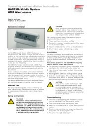
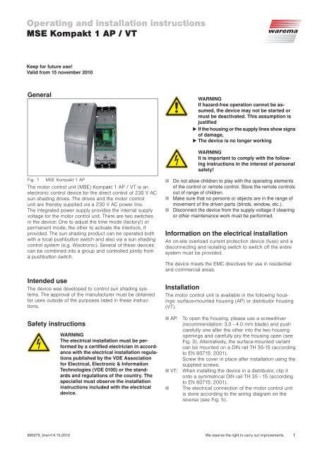
<strong>Operating</strong> <strong>and</strong> <strong>installation</strong> <strong>instructions</strong><strong>MSE</strong> <strong>Kompakt</strong> 1 <strong>AP</strong> / VTKeep for future use!Valid from 15 november 2010GeneralWARNINGIf hazard-free operation cannot be assumed,the device may not be started ormust be deactivated. This assumption isjustified If the housing or the supply lines show signsof damage, The device is no longer workingWARNINGIt is important to comply with the following<strong>instructions</strong> in the interest of personalsafety!Fig. 1 <strong>MSE</strong> <strong>Kompakt</strong> 1 <strong>AP</strong>The motor control unit (<strong>MSE</strong>) <strong>Kompakt</strong> 1 <strong>AP</strong> / VT is anelectronic control device for the direct control of 230 V ACsun shading drives. The drives <strong>and</strong> the motor controlunit are thereby supplied via a 230 V AC power line.The integrated power supply provides the internal supplyvoltage for the motor control unit. There are two switchesin the device: One to adjust the time mode (factory!) orpermanent mode, the other to activate the interlock, ifprovided. The sun shading product can be operated bothwith a local pushbutton switch <strong>and</strong> also via a sun shadingcontrol system (e.g. Wisotronic). Several of these devicescan be combined into a group <strong>and</strong> controlled jointly froma pushbutton switch.Intended useThe device was developed to control sun shading systems.The approval of the manufacturer must be obtainedfor uses outside of the purposes listed in these <strong>instructions</strong>.Safety <strong>instructions</strong>WARNINGThe electrical <strong>installation</strong> must be performedby a certified electrician in accordancewith the electrical <strong>installation</strong> regulationspublished by the VDE Associationfor Electrical, Electronic & InformationTechnologies (VDE 0100) or the st<strong>and</strong>ards<strong>and</strong> regulations of the country. Thespecialist must observe the <strong>installation</strong><strong>instructions</strong> included with the electricaldevice.■ Do not allow children to play with the operating elementsof the control or remote control. Store the remote controlsout of range of children.■ Make sure that no persons or objects are in the range ofmovement of the driven parts (blinds, window, etc.).■ Disconnect the device from the supply voltage if cleaningor other maintenance work must be performed.Information on the electrical <strong>installation</strong>An on-site overload current protection device (fuse) <strong>and</strong> adisconnecting <strong>and</strong> isolating switch to switch off the entiresystem must be provided.The device meets the EMC directives for use in residential<strong>and</strong> commercial areas.InstallationThe motor control unit is available in the following housings:surface-mounted housing (<strong>AP</strong>) or distributor housing(VT).■ <strong>AP</strong>: To open the housing, please use a screwdriver(recommendation: 3.0 - 4.0 mm blade) <strong>and</strong> pushcarefully one after the other into the two housingopenings <strong>and</strong> carefully pry the housing open (seeFig. 3). Alternatively, the surface-mounted variantcan be mounted on a DIN rail TH 35-15 (accordingto EN 60715: 2001).Screw the cover in place after <strong>installation</strong> using thesupplied screws.■ VT: When installing the device in a distributor, clip itonto a symmetrical DIN rail TH 35 - 15 (accordingto EN 60715: 2001).■ The electrical connection of the motor control unitis done according to the wiring diagram on thereverse (see Fig. 5).890279_b•en•14.10.2010 We reserve the right to carry out improvements 1
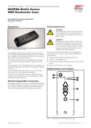
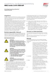
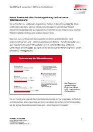
CommissioningThe device is operational after the <strong>installation</strong> has beencompleted <strong>and</strong> the supply voltage applied.FunctionThe <strong>MSE</strong> <strong>Kompakt</strong> 1 <strong>AP</strong> / VT has a double S1 encodingswitch.It is used to select between▸ Time or permanent mode (1) <strong>and</strong> the▸ Activation or deactivation of the interlock (2).This results in different switching states:Local operation with permanent mode (PL):This control behaviour is useful for roller shutters: Theshutter moves according to the operation of the buttoninto the corresponding direction <strong>and</strong> immediately latches.The button may be released <strong>and</strong> the shutter will move untilthe fixed run time of 3 minutes has expired. To release thelatch <strong>and</strong> stop the motor, the button across from the drivecomm<strong>and</strong> must be pressed quickly.Central operation: The local operation is disabled for theduration of central operation; a possibly existing lock isthereby cleared.ONSwitching status ASelected time mode <strong>and</strong>inactivated interlockFig. 21 2NCNOON1 2NCNOSwitching status BSelected permanent mode<strong>and</strong> inactivated interlockON1 2NCNOSwitching status CSelected time mode <strong>and</strong>activated interlockON1 2NCNOSwitching status DSelected permanent mode<strong>and</strong> activated interlockEncoding switch S1 with the following switching functions:1 = Time mode/permanent mode,2 = activated/deactivated interlockNOTE:■ A sunblind pushbutton or a pushbutton withchangeover contact <strong>and</strong> central position"OFF" must be used as local operating element.■ If the drive does not reach the "Up" or"Down" limit switch within 3 minutes, thedrive is cut off automatically, regardlesswhether a local or a central comm<strong>and</strong> wasapplied.Switching state A (factory setting):The switching state A is used to select the time mode <strong>and</strong>deactivate the interlock.Switching state B: Switching state B is used to select thepermanent mode <strong>and</strong> deactivate the interlock.Switching state C:The switching state C is used to select the time mode <strong>and</strong>activate the interlock.Switching state D:The switching state D is used to select the permanentmode <strong>and</strong> activate the interlock.NOTE:■ When you want to lock your sun protectionagainst a window, you must connectan external floating switch or Reed switchbetween "+" <strong>and</strong> the interlock input of themotor control unit (see Fig. 5)The sun protection can then no longer beoperated when Switch 2 is set to the "NC"position if the external floating switch isopen.■ If you did not connect a switch to the interlockinput, the encoder switch "Interlock"must be set to the "NO" position.Local operation with time mode (ZL):Time mode is the ideal control behaviour, e.g. for Venetianblinds: The sun protection product will travel into the correspondingdirection after operating the local pushbutton.The motor control unit switches to the locked state if thepushbutton is pressed longer than 2 seconds. The pushbuttoncan then be released. The sun shading productmoves until the run time of approx. 3 minutes has lapsed.In order to clear the locked state <strong>and</strong> stop the motor,briefly press the button for the opposite direction of movement.Briefly actuate the local pushbutton if you only wantto turn the slats.Multiple series connection:Several motor control units can be combined to a groupvia the control line <strong>and</strong> operated centrally via a pushbuttonswitch. Refer to the wiring diagram on Fig. 5 on thissubject!MaintenanceThere are no parts within the device that require maintenance.In the event of a malfunction, the miniature fusesmay only be exchanged by a certified electrician.LiabilityFailure to comply with the product information in these<strong>instructions</strong> <strong>and</strong> use of the device in a manner that contravenesits intended use <strong>and</strong> purpose may result in themanufacture refusing to honour warranty claims for productdamage. In this case, liability for consequential harmto persons or damage to property will also be excluded.Follow also the <strong>instructions</strong> in the operating manual ofyour sun shading system. The automatic or manual operationof the sun shading system when it is iced over, <strong>and</strong>use of the sun shading system during severe weather, maycause damage <strong>and</strong> must be prevented by the user by takingsuitable precautions.DisposalAfter its use, the device must be disposed off according tolegal regulations or returned to your local recycling centre.2We reserve the right to carry out improvements890279_b•en•14.10.2010
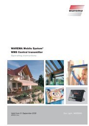
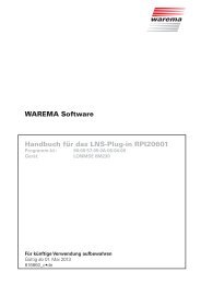
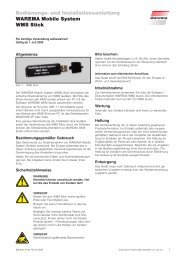
Technical data<strong>MSE</strong> <strong>Kompakt</strong> 1 <strong>AP</strong> / VT Min. Typ. Max. UnitSupply 230 V AC<strong>Operating</strong> voltage 198 230 253 V ACCurrent consumption 5 7 10 mADrive output154 mm212 mmSwitching capacity at230 V AC / cos ϕ = 0.2500 VAMin. load at 5 V DC 10 mAInput controlCentral voltage active 8 24 30 V DC56 mmCentral current active 1 1.5 2 mACentral voltage inactive –0.5 0 4 V DC83 mm-Local voltage active 8 24 30 V DCLocal current active 1 1.5 2 mA60 mmLocal voltage inactive –0.5 0 4 V DCAmbient conditions<strong>Operating</strong> temperature 0 20 40 °CStorage temperature 0 20 50 °CRelative humidity(not condensing)10 40 85 %RHEnclosureDimensions See applicable Fig. 3, 4MiscellaneousFig. 3Surface-mounted housing (<strong>AP</strong>)Weight in surface-typehousingapprox. 260 g41 mm38 mm34 mm13 mm71 mmDegree of protection <strong>AP</strong>modelIP 30Degree of protection VTmodelSafety classIP 20I96 mmConformityAvailable at www.warema.deTerminalsSupply line 2.5 mm 2Fig. 4Distributor housing (VT)Motor line 2.5 mm 2Pushbutton <strong>and</strong> controlline2.5 mm 2St<strong>and</strong>ardsProduct st<strong>and</strong>ardDIN EN 60669-1: 2003-09DIN EN 60669-2-1: 2005-08EMC basic st<strong>and</strong>ardsDIN EN 61000-6-2: 2002-08DIN EN 61000-6-3: 2005-06DIN EN 50366: 2006-11Article numbers<strong>MSE</strong> <strong>Kompakt</strong> 1 <strong>AP</strong> 1002 764<strong>MSE</strong> <strong>Kompakt</strong> 1 VT 1002 765Optional strain relief setfor surface-type housing1002 236Reed switch for interlockfunction623 028Permanent magnet 623 029WAREMA Renkhoff SEHans-Wilhelm-Renkhoff-Strasse 297828 Marktheidenfeld890279_b•en•14.10.2010We reserve the right to carry out improvements3
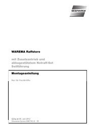
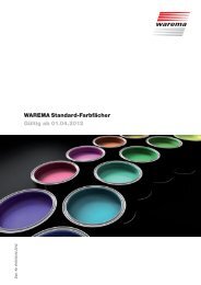
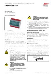
Attention!Motor 1 Only one drive may be Motor 2 Motor 3connected per <strong>MSE</strong>!2 M 1~ 2 M 1~ 2 M 1~3 13 1223311bnblbkPEN3 1 222233331111blgnylPENbnbkblgnylbnbkgnylPower line230 V ACto next <strong>MSE</strong>LN NN L L N NN L L N NN L L3,15 AT 3,15 AT3,15 AT<strong>MSE</strong> <strong>Kompakt</strong> 1<strong>AP</strong> / VTPL NCZL NOLogik Verriegel.PL NCZL NOLogik Verriegel.<strong>MSE</strong> <strong>Kompakt</strong> 1<strong>AP</strong> / VTON<strong>MSE</strong> <strong>Kompakt</strong> 1<strong>AP</strong>, VTONLegend: 4 x 2 x 0,8 mm ∅ screened, single wired 2 x 2 x 0,8 mm ∅ screened, single wired H05RR-F4G 0,75 mm 2 bk, Type WAREMA 3 x 1,5 mm 2UPDOWNVerriegelungP 00+ + gelung P00+ + gelungVerrie-Verrie-00+ + P0V+FPower line230 V AC 50 Hz / 16 ALConnection:PL NCZL NOLogik Verriegel.ONFloating contacts of thesun shading control system /GA Compact1 21 21 2S1S1S1to next <strong>MSE</strong>P/CReed switchP P+DOWNEUP+UPDOWNFor further information, seedocumentation to wiringdiagrams "Anschlusspläne",Art. No.: 816 345Single pushbutton(Motor 3)- Max. group size of 200 motor control units (see voltage dropdiagram).- Central control line length (see voltage drop diagram).- The power line length is limited by the total motor current. Themaximum number of drives per circuit depends on their currentconsumption <strong>and</strong> the upstream fuse.- Max. switching capacity see "Technical data".- Only pushbuttons may be used.- Attention! In case of multiple series connection, combine theup-comm<strong>and</strong> <strong>and</strong> down-comm<strong>and</strong> of the respective <strong>MSE</strong>.Group pushbutton(Motor 1 + 2)Single circuitMultiple series connectionFig. 5Wiring diagram <strong>Kompakt</strong> 1 <strong>AP</strong> / VT4We reserve the right to carry out improvements890279_b•en•14.10.2010