Plug valves - catalogue - Cowan Dynamics
Plug valves - catalogue - Cowan Dynamics
Plug valves - catalogue - Cowan Dynamics

Create successful ePaper yourself
Turn your PDF publications into a flip-book with our unique Google optimized e-Paper software.
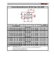
DESIGN FEATURESNON-LUBRICATED PLUG VALVESFluoroSeal®, Non-Lubricated, Sleeved <strong>Plug</strong> Valves incorporate state-of-theartPTFE fluorocarbon seat design. With little required maintenance andtrouble-free operation, a high integrity bubble-tight seal is provided both inlineand to atmosphere. The engineered design features contributing to thesuperiority of our product are described as a function of their specific purposeto ensure a trouble-free extended life.LEAK-FREE PERFORMANCEPTFE fluorocarbon, utilized in the FluoroSeal® sleeve and top seal components,is universally resistant to corrosive media, being inert to all but a few rarelyencountered chemicals. It is a thermoplastic that can be used at a continuousservice temperature of 400°F (204°C) and much higher temperatures can besatisfactorily sustained for shorter periods. Having a very low friction coefficientit is self-lubricating, negating the need for any other form of lubrication. SincePTFE is susceptible to deformation or cold flow as it is put under load, and as itbecomes more pliable at elevated temperatures, precaution is taken to controlthis activity for the valve's intended purpose.The FluoroSeal® internal body configuration has been designed to totallycontain all the edges of the PTFE sleeve at the top, bottom, and around theentire port opening adjacent to the waterway. Any tendency of the sleeveto grow is accommodated by relief recesses designed for this purpose andpositioned at 90 degrees to the body port openings. The port-defining metallips protect the PTFE sleeve from erosion and any possibility of sleeve rotationwithin the body.The waterway in the body has been designed with a contour providing a flowpath that assures minimum flow turbulence characteristics. The critical sealingareas around the top and bottom of the sleeve and around the body portopenings are maintained by means of an adjustable tapered plug compressingthe PTFE sleeve over raised ribs.PLUG-ANSI-DIN-R002-2009ANSI/ASME Class 600 Lbs FluoroSeal®<strong>Plug</strong> ValveThe PTFE top seal components are similarly contained and protected fromdamage. A counter bore is provided at the top of the metal body to encapsulatethe outside diameter of the formed PTFE diaphragm in conjunction with theformed metal diaphragm and to protect it from rupturing by regulating theamount of compression at this point.The inside diameter of the formed PTFE diaphragm, adjacent to the plug stem, isalso contained by means of a unique lip design of the formed metal diaphragmpreventing extrusion and maintaining the stem seal throughout variableservice conditions. This uniquely formed metal diaphragm also provides apositive electrical ground between the plug and body, eliminating the needfor an extra component to fulfill this function as is the case for other valvemanufacturers’ designs.www.fluoroseal<strong>valves</strong>.comA1
DESIGN FEATURESEFFORTLESS EFFICIENCYAs a standard, three point external adjusting bolts in the cover assureequilibrium to the compression of the stem and in-line seals by impartinga balanced force through a metal thrust washer located under the coverabove the formed metal diaphragm. This mechanism provides a multipleseal to atmosphere and a double (downstream & upstream) bidirectionalin-line seal.Independent wrench stops are cast on the cover to limit the stroke at the openand close positions without endangering the integrity of the seal adjustmentas in other manufacturers’ designs. Parallel flats are machined on the sides ofthe plug stem providing positive indication of the direction of flow at all times,independent of other position indicators.Offered as an option on all ANSI/ASME FluoroSeal® <strong>valves</strong>, and standard onall DIN <strong>valves</strong> up to DN 150, is the EZ-SEAL® (patent pending) Top Seal andAdjustment System. Featuring a single point adjustment it eliminates thepossibility of plug side loading. The EZ-SEAL® (patent pending) also introducesa new industry standard by the incorporation of a Min / Max gauge on the cover,giving a visual indication of the remaining service life of a valve and easing theprocess of maintenance planning.PLEDGE OF QUALITYAll major pressure bearing and/or boundary components (body, plug andcover) of FluoroSeal® <strong>valves</strong> are fully traceable to mill test certificates ensuringmaterial authenticity. Quality levels are maintained through continuousinspection and manufacturing surveillance of these and all other components.A concerted effort is made to conform to all regulatory authority requirementswhere and when invoked, in keeping with FluoroSeal Inc.’s pledge of qualityfirst. FluoroSeal® <strong>Plug</strong> Valves comply with the following standards:API 598 API 599 ASME B16.5ASME B16.10 ASME B16.25 ASME B16.34ASME B16.42 ASTM F1545-97 DIN EN 558-1DIN EN 1092-1 DIN EN 12266 MSS SP-55MSS SP-61 ISO/FDI 10497AT A GLANCE∙ Bidirectional flow∙ Quarter-turn operation∙ Non-lubricated∙ Self-cleaning on each operation∙ 2-way and multiport configurations∙ Special service and jacketed designs available∙ All casting components traceable to mill test certificates∙ Investment cast on all materials for sizes 1/2” – 10” (ANSI/ASME Class 150 lbs)PLUG-ANSI-DIN-R002-2009A21 888 269 0220 (Canada & U.S.A.)
DESIGN FEATURES∙ Investment cast on all materials for sizes 1/2” – 6” (ANSI/ASME Class 300 lbs)∙ Investment cast on all materials for sizes 1/2” – 6” (ANSI/ASME Class 600 lbs)∙ Investment cast on all materials for sizes DN 15 – DN 150 (PN 16 – PN 40)∙ Standard heavy-duty gears available on all FluoroSeal® <strong>valves</strong>10 2 9 3 415678ANSI/ASME Class 150 Lbs FluoroSeal® <strong>Plug</strong> Valve Cut-AwayPLUG-ANSI-DIN-R002-2009DESIGN FEATURES SUMMARY1. Bidirectional in-line bubble-tight seal independent of line pressure2. Multiple external bubble-tight seals independent of line pressure3. Direct mechanical three-point adjustment independent of line pressure4. Independent travel stops5. Full encapsulation and retention of all leading edges of PTFE sleeve and topseal components6. Full lip at port openings protects PTFE sleeve7. Contoured waterway ensures minimum flow turbulence characteristic8. No body cavities to entrap flow media9. Positive flow direction indication10. Drilled and tapped flange mounting pads independent of cover and topseal assemblywww.fluoroseal<strong>valves</strong>.comA3
SLEEVED PLUG VALVES — COMPONENTSANSI/ASME Class 150 Lbs FluoroSeal® <strong>Plug</strong> Valve with WrenchMATERIALS OF CONSTRUCTIONBody and <strong>Plug</strong> 1As SpecifiedCover 2Carbon Steel or 304 SSCover Bolts 2Carbon Steel or 304 SSAdjusting Bolts304 SSThrust Washer304 SSMetal Diaphragm 3304 SS, MONEL®Delta RingPTFE FluorocarbonDiaphragmPTFE FluorocarbonSleeve 4PTFE FluorocarbonWrench Operator 5Carbon SteelWrench Bolt 5SteelGear AssemblyHeavy Duty Cast Carbon Steel HousingGear Adaptor 5Hi-Strength SteelGear Mounting Bracket304 SSMounting Bracket Bolts 5Steel1. See BODY & PLUGS MATERIAL TABLE for material selections.2. Cover and bolt materials of standard <strong>valves</strong> will be supplied in accordance with thefollowing table:SPECIFIED BODY COVER ANSI/ASME COVER BOLT DIN COVER BOLTDuctile Iron Carbon Steel ASTM A193 Gr. B7 DIN EN 10269Carbon Steel Carbon Steel ASTM A193 Gr. B7 DIN EN 10269All Other Materials CF8 ASTM A193 Gr. B8 DIN EN 10269Covers can be delivered in the same material as body if specified at time of order.PLUG-ANSI-DIN-R002-20093. MONEL® metal diaphragms will be supplied with <strong>valves</strong> having a MONEL® or nickel trim. Allothers will be supplied with 304 SS diaphragms.4. Glass reinforced PTFE (RTFE), PFA Fluorocarbon, GF2P, Hi-Temp, and UHMWPE sleeves areavailable on special order.5. 304 SS available on special order.A41 888 269 0220 (Canada & U.S.A.)
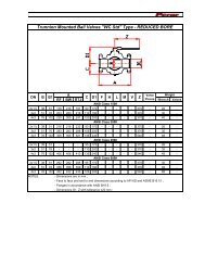
Specialty Valves
SLEEVED PLUG VALVES — 2-WAY2-WAY ANSI/ASME CLASS 150 LBSFlanged EndsWrench or Enclosed Gear OperatedActuators Optional on All SizesDimensions to ANSI B16.5 & B16.10E = Clearance required for resleeving measured from center lineEG = Enclosed gear operatedN = Number of holesTwo (2) top holes in flanges are tapped with UNC threads. See Hole-UNC column1Six (6) top holes* 2 1/2” <strong>valves</strong> are made from 3” casting, but flanges are machined to 2 1/2” dimensionsSIZE L H D K g b f d Q Weight E N Holeinmm in mm in mm in mm in mm in mm in mm in mm in mm kg lbs in mm # UNC1/2” 4.25 108.00 3.38 86.00 3.50 88.90 2.38 60.50 1.38 35.00 0.37 9.50 0.06 1.52 0.63 16.00 8.00 203.00 2.3 5.0 6.38 162.10 4 -3/4” 4.63 117.50 3.38 86.00 3.88 98.50 2.75 69.90 1.68 42.90 0.37 9.50 0.06 1.52 0.63 16.00 8.00 203.00 2.7 6.0 6.38 162.10 4 -1” 5.00 127.00 4.50 114.00 4.25 108.00 3.13 79.50 2.00 50.80 0.44 11.20 0.06 1.52 0.63 16.00 9.00 229.00 3.6 8.0 8.50 215.90 4 -1 1/2” 6.50 165.10 5.31 135.00 5.00 127.00 3.88 98.60 2.88 73.20 0.56 14.20 0.06 1.52 0.63 16.00 14.25 362.00 6.4 14.0 10.38 263.70 4 -2” 7.00 177.80 6.25 159.00 6.00 152.40 4.75 120.70 3.63 92.00 0.63 16.00 0.06 1.52 0.75 19.00 16.50 419.00 10.5 23.0 12.25 311.20 4 -*2 1/2” 8.00 203.20 6.56 167.00 7.50 190.50 5.50 139.70 4.13 104.60 0.75 19.00 0.06 1.52 0.75 19.00 16.50 419.00 16.4 36.0 12.63 320.80 4 -3” 8.00 203.20 6.56 167.00 7.50 190.50 6.00 152.40 5.00 127.00 0.75 19.00 0.06 1.52 0.75 19.00 16.50 419.00 16.4 36.0 13.63 346.20 4 -4” 9.00 228.60 7.63 194.00 9.00 228.60 7.50 190.50 6.19 157.20 0.94 23.90 0.06 1.52 0.75 19.00 23.63 600.00 26.8 59.0 16.25 412.80 8 -4” EG 9.00 228.60 9.10 231.00 9.00 228.60 7.50 190.50 6.19 157.20 0.94 23.90 0.06 1.52 0.75 19.00 7.25 184.00 35.9 79.0 17.63 447.80 8 -6” EG 10.50 266.70 10.80 274.00 11.00 279.40 9.50 241.30 8.50 215.90 1.00 25.40 0.06 1.52 0.88 22.40 7.25 184.00 55.5 122.0 21.75 552.50 8 -8” EG 11.50 292.10 12.75 324.00 13.50 342.90 11.75 298.50 10.63 269.80 1.13 28.70 0.06 1.52 0.88 22.40 9.75 248.00 100.0 220.0 26.63 676.40 8 3/4"-1010” EG 13.00 330.20 14.68 373.00 16.00 406.40 14.25 362.00 12.75 323.90 1.19 30.20 0.06 1.52 1.00 25.40 9.75 248.00 150.0 330.0 31.25 793.80 12 7/8"-912” EG 14.00 355.60 16.40 417.00 19.00 482.60 17.00 431.80 15.00 381.00 1.25 31.80 0.06 1.52 1.00 25.40 13.75 349.25 198.6 437.0 33.75 857.30 12 7/8"-914” EG 15.00 381.00 17.40 442.00 21.00 533.40 18.75 476.30 16.25 412.80 1.38 35.10 0.06 1.52 1.12 28.40 13.75 349.25 295.0 650.0 34.75 882.70 12 1"-816” EG 30.00 762.00 21.29 540.72 23.00 584.20 21.25 539.75 18.50 469.90 1.38 35.05 0.06 1.52 1.13 28.58 9.85 250.19 - - 46.00 1168.40 16 1"-818” EG 34.00 863.60 21.29 540.84 25.00 635.00 22.75 577.85 21.00 533.40 1.50 38.10 0.06 1.52 1.25 31.75 9.85 250.19 - - 46.00 1168.40 16 1 1/8"-820” EG 36.00 914.40 27.43 696.70 27.00 685.80 25.00 635.00 23.00 584.20 1.62 41.15 0.06 1.52 1.25 31.75 9.85 250.19 - - 57.63 1463.80 20 1 1/8"-8 124” EG 42.00 1066.8 27.43 696.70 31.00 787.40 29.50 749.30 27.25 692.15 1.81 45.97 0.06 1.52 1.38 34.93 9.85 250.19 - - 57.63 1463.80 20 1 1/4"-82-WAY ANSI/ASME CLASS 300 LBSFlanged EndsWrench or Enclosed Gear OperatedActuators Optional on All SizesDimensions to ANSI B16.5 & B16.10E = Clearance required for resleeving measured from center lineEG = Enclosed gear operatedN = Number of holesTwo (2) top holes in flanges are tapped with UNC threads. See Hole-UNC column1Four (4) top holes* 2 1/2” <strong>valves</strong> are made from 3” casting, but flanges are machined to 2 1/2” dimensionsSIZE L H D K g b f d Q Weight E N Holeinmm in mm in mm in mm in mm in mm in mm in mm in mm kg lbs in mm # UNC1/2” 5.50 139.70 3.38 86.00 3.75 95.30 2.63 66.80 1.38 35.00 0.56 14.20 0.06 1.52 0.63 16.00 8.00 203.00 3.2 7.0 6.38 162.10 4 -3/4” 6.00 152.40 3.38 86.00 4.63 117.60 3.25 82.60 1.69 42.70 0.63 16.00 0.06 1.52 0.75 19.00 8.00 203.00 4.1 9.0 6.38 162.10 4 -1” 6.50 165.10 4.50 114.00 4.88 124.00 3.50 88.90 2.00 50.80 0.69 17.50 0.06 1.52 0.75 19.00 9.00 229.00 5.5 12.0 8.50 215.90 4 -1 1/2” 7.50 190.50 5.31 135.00 6.13 155.70 4.50 114.30 2.88 73.20 0.81 20.60 0.06 1.52 0.88 22.40 14.25 362.00 9.5 21.0 10.38 263.70 4 -2” 8.50 215.90 6.25 159.00 6.50 165.10 5.00 127.00 3.63 92.00 0.88 22.40 0.06 1.52 0.75 19.00 16.50 419.00 13.2 29.0 12.25 311.20 8 -*2 1/2” 11.13 282.70 6.56 167.00 8.25 209.60 5.88 149.40 4.13 104.60 1.13 28.70 0.06 1.52 0.88 22.40 16.50 419.00 21.8 48.0 12.63 320.80 8 -3” 11.13 282.70 6.56 167.00 8.25 209.60 6.63 168.40 5.00 127.00 1.13 28.70 0.06 1.52 0.88 22.40 16.50 419.00 21.8 48.0 13.63 346.20 8 -4” 12.00 304.80 7.63 194.00 10.00 254.00 7.88 200.20 6.19 157.20 1.25 31.80 0.06 1.52 0.88 22.40 23.63 600.00 42.0 92.0 16.25 412.80 8 -4” EG 12.00 304.80 9.10 231.00 10.00 254.00 7.88 200.20 6.19 157.20 1.25 31.80 0.06 1.52 0.88 22.40 7.25 184.00 54.0 119.0 17.63 447.80 8 -6” EG 15.88 403.40 10.80 274.00 12.50 317.50 10.63 270.00 8.50 215.90 1.44 36.60 0.06 1.52 0.88 22.40 7.25 184.00 91.4 201.0 21.75 552.50 12 -8” EG 16.50 419.10 12.75 324.00 15.00 381.00 13.00 330.20 10.63 269.80 1.63 41.40 0.06 1.52 1.00 25.40 9.75 248.00 141.4 311.0 26.63 676.40 12 7/8"-910” EG 18.00 457.20 14.68 373.00 17.50 444.50 15.25 387.40 12.75 323.90 1.88 47.80 0.06 1.52 1.13 28.70 9.75 248.00 210.9 464.0 31.25 793.80 16 1"-812” EG 19.75 501.70 16.40 417.00 20.50 520.70 17.75 450.90 15.00 381.00 2.00 50.80 0.06 1.52 1.25 31.80 13.75 349.25 279.0 614.0 33.75 857.30 16 1 1/8"-814” EG 30.00 762.00 17.40 442.00 23.00 584.20 20.25 514.40 16.25 412.80 2.12 53.80 0.06 1.52 1.25 31.80 13.75 349.25 363.0 800.0 34.75 882.70 20 -16” EG 33.00 838.20 21.29 540.72 25.50 647.70 22.50 571.50 18.50 469.90 2.19 55.63 0.06 1.52 1.38 34.93 9.85 698.50 - - 46.00 1168.40 20 1 1/4"-818” EG 36.00 914.40 21.29 540.84 28.00 711.20 24.75 628.65 21.00 533.40 2.31 58.67 0.06 1.52 1.38 34.93 9.85 698.50 - - 46.00 1168.40 24 -20” EG 39.00 990.60 27.43 696.70 30.50 774.70 27.00 685.80 23.00 584.20 2.44 61.98 0.06 1.52 1.38 34.93 9.85 698.50 - - 57.63 1463.80 24 1 1/4"-8 124” EG 45.00 1143.0 27.43 696.70 36.00 914.40 32.00 812.80 27.25 692.15 2.69 68.33 0.06 1.52 1.63 41.28 9.85 698.50 - - 57.63 1463.80 24 1 1/2"-8PLUG-ANSI-DIN-R002-2009BA21 888 269 0220 (Canada & U.S.A.)
SLEEVED PLUG VALVES — 2-WAY2-WAY ANSI/ASME CLASS 150/300/600 LBSScrewed EndsWrench OperatedActuators Optional on All SizesDimensions to ANSI B16.11E = Clearance required for resleeving measured from center lineSIZE L H Q Weight Ein mm in mm in mm kg lbs in mm1/2” 3.93 100.00 3.38 85.90 8.00 203.00 2.0 4.4 6.38 162.103/4” 3.93 100.00 3.38 85.50 8.00 203.00 2.0 4.4 6.38 162.101” 5.50 140.00 4.50 114.00 9.00 229.00 3.0 6.6 8.50 215.901 1/2” 6.30 160.00 5.31 135.00 14.25 362.00 6.0 13.2 10.38 263.702” 7.87 200.00 6.25 159 .00 16.50 419.00 10.0 22.0 12.25 311.202 1/2” 7.87 200.00 6.56 167.00 16.50 419.00 11.0 24.0 12.63 320.802-WAY ANSI/ASME CLASS 150/300/600 LBSSocket Weld EndsWrench OperatedActuators Optional on All SizesDimensions to ANSI B16.11E = Clearance required for resleeving measured from center lineSIZE L H D J F Q Weight Ein mm in mm in mm in mm in mm in mm kg lbs in mm1/2” 3.93 100.00 3.38 85.90 0.85 21.70 0.55 14.00 0.37 9.50 8.00 203.00 2.0 4.4 6.38 162.103/4” 3.93 100.00 3.38 85.50 1.07 27.20 0.75 19.00 0.50 12.70 8.00 203.00 2.0 4.4 6.38 162.101” 5.50 140.00 4.50 114.00 1.34 34.00 0.98 25.00 0.50 12.70 9.00 229.00 3.0 6.6 8.50 215.901 1/2” 6.30 160.00 5.31 135.00 1.92 48.80 1.50 38.00 0.50 12.70 14.25 362.00 6.0 13.2 10.38 263.702” 7.87 200.00 6.25 159 .00 2.40 61.00 1.97 50.00 0.66 16.70 16.50 419.00 10.0 22.0 12.25 311.202 1/2” 7.87 200.00 6.56 167.00 2.91 73.91 2.41 61.21 7.88 200.15 16.50 419.00 11.0 24.0 12.63 320.80PLUG-ANSI-DIN-R002-2009BA41 888 269 0220 (Canada & U.S.A.)
SLEEVED PLUG VALVES — 2-WAYFull Port ANSI/ASME Class 300 Lbs FluoroSeal® Sleeved <strong>Plug</strong> ValveFULL PORT PLUG VALVESYou like the design features of our standard port <strong>valves</strong>, but are concernedabout flow restrictions?Now, you have the best of two worlds:FluoroSeal® proven design combined with non-restricted flow.The new F Series is available in ANSI/ASME Classes 150, 300 and 600 lbs.Size range from 1” to 10”.Same material offering as our standard <strong>valves</strong>.PLUG-ANSI-DIN-R002-2009FULL PORT ANSI/ASME CLASS 150 LBSFlanged EndsWrench or Enclosed Gear OperatedActuators Optional on All SizesE = Clearance required for resleeving measured from center lineEG = Enclosed gear operatedN = Number of holesTwo (2) top holes in flanges are tapped with UNC threads. See Hole-UNC columnSIZE L H D K g b f d Q Weight E N Holeinmm in mm in mm in mm in mm in mm in mm in mm in mm kg lbs in mm # UNC1/2” 4.25 108.00 3.38 85.90 3.50 88.90 2.38 60.50 1.38 35.10 0.37 9.40 0.06 1.52 0.62 15.70 8.00 203.00 2.3 5.0 6.38 162.10 4 -3/4” 4.63 117.50 3.38 86.00 3.88 98.50 2.75 69.90 1.68 42.90 0.37 9.50 0.06 1.52 0.63 16.00 8.00 203.00 - - 6.38 162.10 4 -1” 6.50 165.10 5.06 128.6 4.88 124.00 3.12 79.20 2.00 50.80 0.69 17.50 0.06 1.52 0.62 15.70 14.25 362.00 - - 5.75 146.10 4 -1 1/2” 7.50 190.50 5.81 147.50 6.12 155.40 3.88 98.60 2.88 73.20 0.81 20.60 0.06 1.52 0.62 15.70 16.50 419.00 - - 6.88 174.80 4 -2” 8.50 215.90 9.25 235.00 6.50 165.10 4.75 120.7 3.62 91.90 0.88 22.40 0.06 1.52 0.75 19.10 23.63 600.00 - - 7.20 182.90 4 5/8"-113” EG 11.13 282.70 9.25 235.00 8.25 209.60 6.00 152.40 5.00 127.00 1.12 28.40 0.06 1.52 0.75 19.10 23.63 600.00 - - 7.75 196.90 4 5/8"-114” EG 12.00 304.80 11.00 279.40 10.00 254.00 7.50 190.50 6.19 157.20 1.25 31.80 0.06 1.52 0.75 19.10 9.75 248.00 - - 10.48 266.20 4 5/8"-116” EG 22.00 558.80 - - 12.50 317.50 9.50 241.30 8.50 215.90 1.44 36.60 0.06 1.52 0.88 22.40 - - - - 13.25 336.60 8 -8” EG 27.00 685.80 17.81 452.50 15.00 381.00 11.75 298.50 10.62 269.70 1.62 41.10 0.06 1.52 0.88 22.40 13.75 349.00 - - 17.13 435.10 4 3/4"-1010” EG 32.50 825.50 14.91 378.74 17.52 445.01 14.25 361.95 12.75 323.85 1.81 45.97 0.06 1.52 1.00 25.40 13.75 349.00 - - 21.13 536.70 12 -www.fluoroseal<strong>valves</strong>.comBA5
SLEEVED PLUG VALVES — 2-WAYFULL PORT ANSI/ASME CLASS 300 LBSFlanged EndsWrench or Enclosed Gear OperatedActuators Optional on All SizesE = Clearance required for resleeving measured from center lineEG = Enclosed gear operatedN = Number of holesTwo (2) top holes in flanges are tapped with UNC threads. See Hole-UNC columnSIZE L H D K g b f d Q Weight E N Holeinmm in mm in mm in mm in mm in mm in mm in mm in mm kg lbs in mm # UNC1/2” 5.50 139.70 3.38 85.90 3.75 95.30 2.62 66.50 1.38 35.10 0.56 14.20 0.06 1.52 0.62 15.70 8.00 203.00 3.2 7.0 6.38 162.10 4 -3/4” 6.00 152.40 - - 3.75 95.30 3.25 82.60 1.69 42.90 0.62 15.70 0.06 1.52 0.75 19.10 - - - - - - 4 -1” 6.50 165.10 5.06 128.6 4.88 124.00 3.50 88.90 2.00 50.80 0.69 17.50 0.06 1.52 0.75 19.10 14.25 362.00 - - 5.75 146.10 4 -1 1/2” 7.50 190.50 5.81 147.50 6.12 155.40 4.50 114.30 2.88 73.20 0.81 20.60 0.06 1.52 0.88 22.40 16.50 419.00 - - 6.88 174.80 4 -2” 8.50 215.90 9.25 235.00 6.50 165.10 5.00 127.00 3.62 91.90 0.88 22.40 0.06 1.52 0.75 19.10 23.63 600.00 - - 7.20 182.90 8 -3” EG 11.13 282.70 9.25 235.00 8.25 209.60 6.62 168.10 5.00 127.00 1.12 28.40 0.06 1.52 0.88 22.40 23.63 600.00 - - 7.75 196.90 8 -4” EG 12.00 304.80 11.00 279.40 10.00 254.00 7.88 200.20 6.19 157.20 1.25 31.80 0.06 1.52 0.88 22.40 9.75 248.00 - - 10.48 266.20 8 -6” EG 22.00 558.80 - - 12.50 317.50 10.62 269.70 8.50 215.90 1.44 36.60 0.06 1.52 0.88 22.40 - - - - 13.25 336.60 12 -8” EG 27.00 685.80 17.81 452.50 15.00 381.00 13.00 330.20 10.62 269.70 1.62 41.10 0.06 1.52 1.00 25.40 13.75 349.00 - - 17.13 435.10 4 7/8"-910” EG 32.50 825.50 14.91 378.74 17.50 444.50 15.25 387.35 12.75 323.85 1.81 45.97 0.06 1.52 1.13 28.58 13.75 349.00 - - 21.13 536.70 16 -FULL PORT ANSI/ASME CLASS 600 LBSFlanged EndsWrench or Enclosed Gear OperatedActuators Optional on All SizesE = Clearance required for resleeving measured from center lineEG = Enclosed gear operatedN = Number of holesTwo (2) top holes in flanges are tapped with UNC threads. See Hole-UNC columnSIZE L H D K g b f d Q Weight E N Holeinmm in mm in mm in mm in mm in mm in mm in mm in mm kg lbs in mm # UNC1/2” 5.50 139.70 3.38 85.90 3.75 95.30 2.62 66.50 1.38 35.10 0.56 14.20 0.06 1.52 0.62 15.70 8.00 203.00 - - 6.38 162.10 4 -3/4” 6.00 152.40 - - 3.75 95.30 3.25 82.60 1.69 42.90 0.62 15.70 0.06 1.52 0.75 19.10 - - - - - - 4 -1” 6.50 165.10 5.06 128.6 4.88 124.00 3.50 88.90 2.00 50.80 0.69 17.50 0.06 1.52 0.75 19.10 14.25 362.00 - - 5.75 146.10 4 -1 1/2” 7.50 190.50 5.81 147.50 6.12 155.40 4.50 114.30 2.88 73.20 0.81 20.60 0.06 1.52 0.88 22.40 16.50 419.00 - - 6.88 174.80 4 -2” 8.50 215.90 9.25 235.00 6.50 165.10 5.00 127.00 3.62 91.90 0.88 22.40 0.06 1.52 0.75 19.10 23.63 600.00 - - 7.20 182.90 8 -3” EG 11.13 282.70 9.25 235.00 8.25 209.60 6.62 168.10 5.00 127.00 1.12 28.40 0.06 1.52 0.88 22.40 23.63 600.00 - - 7.75 196.90 8 -4” EG 12.00 304.80 11.00 279.40 10.00 254.00 8.50 215.90 6.19 157.20 1.25 31.80 0.06 1.52 1.00 25.40 9.75 248.00 - - 10.48 266.20 8 -6” EG 22.00 558.80 - - 12.50 317.50 11.50 292.10 8.50 215.90 1.44 36.60 0.06 1.52 1.12 28.40 - - - - 13.25 336.60 12 -8” EG 27.00 685.80 17.81 452.50 15.00 381.00 13.75 349.30 10.62 269.70 1.62 41.10 0.06 1.52 1.25 31.80 13.75 349.00 - - 17.13 435.10 12 -10” EG 31.00 787.40 14.91 378.74 20.00 508.00 17.00 431.80 12.75 323.85 2.50 63.50 0.25 6.35 1.38 35.10 9.85 250.19 - - 21.13 536.70 16 -PLUG-ANSI-DIN-R002-2009BA61 888 269 0220 (Canada & U.S.A.)
Specialty Valves
SLEEVED PLUG VALVES — MULTIPORTFLOW ARRANGEMENTSFlow is indicated by the arrow(s). When rotating plugs FA2, FA3 or FA4 atransflow condition exists at all times. Only position B in plugs FA1 and FA5will provide a complete shutoff condition. Valves will be supplied with quarterturn(90°) operators as standard. Should a half-turn (180°) operator be needed,please specify. ANSI/ASME class 600 lbs available upon request.FA 1 FA 2 FA 3 FA 4 FA 5Position C − 180°Position B − 90°Position A − 0° <strong>Plug</strong> TypeMULTIPORT ASME/ANSI CLASS 150 LBSFlanged EndsWrench or Enclosed Gear OperatedActuators Optional on All SizesDimensions to ANSI B16.5 & B16.10E = Clearance required for resleeving measured from center lineEG = Enclosed gear operatedN = Number of holesTwo (2) top holes in flanges are tapped with UNC threads. See Hole-UNC column* 2 1/2” <strong>valves</strong> are made from 3” casting, but flanges are machined to 2 1/2” dimensionsSIZE L H D K g b f d Q G Weight E N Holeinmm in mm in mm in mm in mm in mm in mm in mm in mm in mm kg lbs in mm # UNC1/2” 4.25 108.00 3.38 86.00 3.50 88.90 2.38 60.50 1.38 35.00 0.37 9.50 0.06 1.60 0.63 16.00 8.00 203.00 2.75 69.85 2.5 6.0 6.38 162.10 4 -3/4” 4.63 117.50 3.38 86.00 3.88 98.50 2.75 69.90 1.68 42.90 0.37 9.50 0.06 1.60 0.63 16.00 8.00 203.00 2.88 73.15 3.2 7.0 6.38 162.10 4 -1” 5.00 127.00 4.50 114.00 4.25 108.00 3.13 79.50 2.00 50.80 0.44 11.20 0.06 1.60 0.63 16.00 9.00 229.00 3.50 88.90 5.0 11.0 8.50 215.90 4 -1 1/2” 6.50 165.10 5.31 135.00 5.00 127.00 3.88 98.60 2.88 73.20 0.56 14.20 0.06 1.60 0.63 16.00 14.25 362.00 4.13 104.90 8.2 18.0 10.38 263.70 4 -2” 7.00 177.80 6.25 159.00 6.00 152.40 4.75 120.70 3.63 92.00 0.63 16.00 0.06 1.60 0.75 19.00 16.50 419.00 4.50 114.30 13.6 30.0 12.25 311.20 4 -*2 1/2” 8.00 203.20 6.56 167.00 7.50 190.50 5.50 139.70 4.13 104.60 0.75 19.00 0.06 1.60 0.75 19.00 16.50 419.00 5.13 130.30 18.2 40.0 12.63 320.80 4 -3” 8.00 203.20 6.56 167.00 7.50 190.50 6.00 152.40 5.00 127.00 0.75 19.00 0.06 1.60 0.75 19.00 16.50 419.00 5.13 130.30 19.1 42.0 13.63 346.20 4 -4” 9.00 228.60 7.63 194.00 9.00 228.60 7.50 190.50 6.19 157.20 0.94 23.90 0.06 1.60 0.75 19.00 23.63 600.00 6.00 152.40 32.7 72.0 16.25 412.80 8 -4” EG 9.00 228.60 9.10 231.00 9.00 228.60 7.50 190.50 6.19 157.20 0.94 23.90 0.06 1.60 0.75 19.00 7.25 184.00 6.00 152.40 41.4 91.0 17.63 447.80 8 -6” EG 10.50 266.70 10.80 274.00 11.00 279.40 9.50 241.30 8.50 215.90 1.00 25.40 0.06 1.60 0.88 22.40 7.25 184.00 7.50 190.50 70.8 148.0 21.75 552.50 8 -8” EG 11.50 292.10 12.75 324.00 13.50 342.90 11.75 298.50 10.63 269.80 1.13 28.70 0.06 1.60 0.88 22.40 9.75 248.00 9.00 228.60 117.5 259.0 26.63 676.40 8 3/4"-1010” EG 13.00 330.20 14.68 373.00 16.00 406.40 14.25 362.00 12.75 323.90 1.19 30.20 0.06 1.60 1.00 25.40 9.75 248.00 11.00 279.40 181.9 401.0 31.25 793.80 12 7/8"-912” EG 14.00 355.60 16.40 417.00 19.00 482.60 17.00 431.80 15.00 381.00 1.25 31.80 0.06 1.60 1.00 25.40 13.75 349.25 13.75 349.25 - - 33.75 857.30 12 7/8"-914” EG 15.00 381.00 17.40 442.00 21.00 533.40 18.75 476.30 16.25 412.80 1.38 35.10 0.06 1.60 1.12 28.40 13.75 349.25 15.00 381.00 - - 34.75 882.70 12 1"-8PLUG-ANSI-DIN-R002-2009BB21 888 269 0220 (Canada & U.S.A.)
SLEEVED PLUG VALVES — MULTIPORTMULTIPORT ASME/ANSI CLASS 300 LBSFlanged EndsWrench or Enclosed Gear OperatedActuators Optional on All SizesDimensions to ANSI B16.5 & B16.10E = Clearance required for resleeving measured from center lineEG = Enclosed gear operatedN = Number of holesTwo (2) top holes in flanges are tapped with UNC threads. See Hole-UNC column* 2 1/2” <strong>valves</strong> are made from 3” casting, but flanges are machined to 2 1/2” dimensionsSIZE L H D K g b f d Q G Weight E Nin mm in mm in mm in mm in mm in mm in mm in mm in mm in mm kg lbs in mm #Hole-UNC1/2” 5.50 139.70 3.38 86.00 3.75 95.30 2.63 66.80 1.38 35.00 0.56 14.20 0.06 1.60 0.63 16.0 8.00 203.00 2.88 73.20 3.2 7.0 6.38 162.10 4 -3/4” 6.00 152.40 3.38 86.00 4.63 117.60 3.25 82.60 1.69 42.70 0.63 16.00 0.06 1.60 0.75 19.00 8.00 203.00 3.00 76.20 4.1 9.0 6.38 162.10 4 -1” 6.50 165.10 4.50 114.00 4.88 124.00 3.50 88.90 2.00 50.80 0.69 17.50 0.06 1.60 0.75 19.00 9.00 229.00 3.75 95.30 5.5 12.0 8.50 215.90 4 -1 1/2” 7.50 190.50 5.31 135.00 6.13 155.70 4.50 114.30 2.88 73.20 0.81 20.60 0.06 1.60 0.88 22.40 14.25 362.00 4.38 111.30 9.5 21.0 10.38 263.70 4 -2” 8.50 215.90 6.25 159.00 6.50 165.10 5.00 127.00 3.63 92.00 0.88 22.40 0.06 1.60 0.75 19.00 16.50 419.00 4.75 120.70 13.2 29.0 12.25 311.20 8 -*2 1/2” 11.13 282.70 6.56 167.00 8.25 209.60 5.88 149.40 4.13 104.60 1.13 28.70 0.06 1.60 0.88 22.40 16.50 419.00 5.56 141.20 21.8 48.0 12.63 320.80 8 -3” 11.13 282.70 6.56 167.00 8.25 209.60 6.63 168.40 5.00 127.00 1.13 28.70 0.06 1.60 0.88 22.40 16.50 419.00 5.56 141.20 21.8 48.0 13.63 346.20 8 -4” 12.00 304.80 7.63 194.00 10.00 254.00 7.88 200.20 6.19 157.20 1.25 31.80 0.06 1.60 0.88 22.40 23.63 600.00 6.75 171.50 42.0 92.0 16.25 412.80 8 -4” EG 12.00 304.80 9.10 231.00 10.00 254.00 7.88 200.20 6.19 157.20 1.25 31.80 0.06 1.60 0.88 22.40 7.25 184.00 6.75 171.50 54.0 119.0 17.63 447.80 8 -6” EG 15.88 403.40 10.80 274.00 12.50 317.50 10.63 270.00 8.50 215.90 1.44 36.6 0.06 1.60 0.88 22.40 7.25 184.00 8.50 215.90 91.4 201.0 21.75 552.50 12 -8” EG 16.50 419.10 12.75 324.00 15.00 381.00 13.00 330.20 10.63 269.80 1.63 41.40 0.06 1.60 1.00 25.40 9.75 248.00 10.00 254.00 141.4 311.0 26.63 676.40 12 7/8"-710” EG 18.00 457.20 14.68 373.00 17.50 444.50 15.25 387.40 12.75 323.90 1.88 47.80 0.06 1.60 1.13 28.70 9.75 248.00 - - 210.9 464.0 31.25 793.80 16 1"-812” EG 19.75 501.70 16.40 417.00 20.50 520.70 17.75 450.90 15.00 381.00 2.00 50.80 0.06 1.60 1.25 31.80 13.75 349.25 14.00 355.60 279.0 614.0 33.75 857.30 16 1 1/8"-714” EG 30.00 762.00 17.40 442.00 23.00 584.20 20.25 514.40 16.25 412.80 2.12 53.80 0.06 1.60 1.25 31.80 13.75 349.25 - - 363.0 800.0 34.75 882.70 20 -PLUG-ANSI-DIN-R002-2009MULTIPORT ASME/ANSI CLASS 150/300/600 LBSScrewed EndsWrench OperatedActuators Optional on All SizesDimensions to ANSI B16.11E = Clearance required for resleeving measured from center lineSIZE L H G Q Weight Ein mm in mm in mm in mm kg lbs in mm1/2” 3.93 100.00 3.38 85.90 1.69 42.90 8.00 203.00 2.1 4.7 6.38 162.103/4” 3.93 100.00 3.38 85.50 1.80 45.70 8.00 203.00 2.1 4.7 6.38 162.101” 5.50 140.00 4.50 114.00 2.38 60.50 9.00 229.00 3.2 7.1 8.50 215.901 1/2” 6.30 160.00 5.31 135.00 2.88 73.20 14.25 362.00 6.4 14.2 10.38 263.702” 7.87 200.00 6.25 159 .00 3.38 85.90 16.50 419.00 10.4 23.0 12.25 311.20www.fluoroseal<strong>valves</strong>.comBB3
SLEEVED PLUG VALVES — MULTIPORTMULTIPORT ASME/ANSI CLASS 150/300/600 LBSSocket Weld EndsWrench OperatedActuators Optional on All SizesDimensions to ANSI B16.11E = Clearance required for resleeving measured from center lineSIZE L H D J F G Q Weight Ein mm in mm in mm in mm in mm in mm in mm kg lbs in mm1/2” 3.93 100.00 3.38 85.90 0.85 21.70 0.55 14.00 0.37 9.50 1.69 42.90 8.00 203.00 2.1 4.7 6.38 162.103/4” 3.93 100.00 3.38 85.50 1.07 27.20 0.75 19.00 0.50 12.70 1.80 45.70 8.00 203.00 2.1 4.7 6.38 162.101” 5.50 140.00 4.50 114.00 1.34 34.00 0.98 25.00 0.50 12.70 2.38 60.50 9.00 229.00 3.2 7.1 8.50 215.901 1/2” 6.30 160.00 5.31 135.00 1.92 48.80 1.50 38.00 0.50 12.70 2.88 73.20 14.25 362.00 6.4 14.2 10.38 263.702” 7.87 200.00 6.25 159 .00 2.40 61.00 1.97 50.00 0.66 16.70 3.38 85.90 16.50 419.00 10.4 23.0 12.25 311.20MULTIPORT DIN PN 16 & PN 40Flanged EndsWrench or Enclosed Gear OperatedActuators Optional on All SizesDimensions to DIN EN 1092-1 & DIN EN 558-1Enclosed gear optional on DN 100, and standard on DN 125 and DN 150E = Clearance required for resleeving measured from center lineN = Number of holesTwo (2) top holes in flanges are tapped with metric threads. See Bolt Size column*According to DIN EN 1092-2 (Cast Iron Flanges) and DIN prEN 1092-3 (Copper AlloyFlanges), the flanges in this DN and PN may be supplied with four (4) holes. Where steelflanges are required with four (4) holes, these may be supplied by agreement betweenmanufacturer and purchaser.SIZE PN L H D K g b f d Q G Weight E Nmm mm mm mm mm mm mm mm mm mm kg mm #Bolt SizeDN 15 16 & 40 130.00 145.00 95.00 65.00 45.00 16.00 2.00 14.00 210.00 65.00 - 131.00 4 M12DN 20 16 & 40 150.00 145.00 105.00 75.00 58.00 18.00 2.00 14.00 210.00 75.00 - 131.00 4 M12DN 25 16 & 40 160.00 145.00 115.00 85.00 68.00 18.00 2.00 14.00 210.00 80.00 - 131.00 4 M12DN 32 16 & 40 180.00 176.00 140.00 100.00 78.00 18.00 2.00 18.00 262.50 90.00 - 161.00 4 M16DN 40 16 & 40 200.00 176.00 150.00 110.00 88.00 18.00 2.00 18.00 262.50 100.00 - 161.00 4 M16DN 5016 230.00 195.00 165.00 125.00 102.00 18.00 2.00 18.00 419.10 115.00 - 189.00 4 M1640 230.00 195.00 165.00 125.00 102.00 20.00 2.00 18.00 419.10 115.00 - 189.00 4 M16DN 6516 290.00 173.00 185.00 145.00 122.00 18.00 2.00 18.00 419.10 145.00 - 217.00 8* M1640 290.00 173.00 185.00 145.00 122.00 22.00 2.00 18.00 419.10 145.00 - 217.00 8 M16DN 8016 310.00 173.00 200.00 160.00 138.00 20.00 2.00 18.00 419.10 155.00 - 217.00 8 M1640 310.00 173.00 200.00 160.00 138.00 24.00 2.00 18.00 419.10 155.00 - 217.00 8 M16DN 10016 350.00 200.00 220.00 180.00 158.00 20.00 2.00 18.00 618.00 175.00 - 270.00 8 M1640 350.00 200.00 235.00 190.00 162.00 24.00 2.00 22.00 618.00 175.00 - 270.00 8 M20DN 12516 325.00 303.00 250.00 210.00 188.00 22.00 2.00 18.00 184.20 163.00 - 370.00 8 M1640 325.00 303.00 270.00 220.00 188.00 26.00 2.00 26.00 184.20 163.00 - 370.00 8 M24DN 15016 350.00 290.00 285.00 240.00 212.00 22.00 2.00 22.00 184.20 175.00 - 370.00 8 M2040 350.00 290.00 300.00 250.00 218.00 28.00 2.00 26.00 184.20 175.00 - 370.00 8 M24PLUG-ANSI-DIN-R002-2009BB41 888 269 0220 (Canada & U.S.A.)
Specialty Valves
SLEEVED PLUG VALVES — SEVERE SERVICE (FE)SEVERE SERVICE (FE) PLUG VALVESFluoroSeal Inc. has developed the Severe Service (FE) Sleeved <strong>Plug</strong>Valve for tight emission control in more demanding applications.This valve is intended for applications in processes involving thermalcycling or a high number of mechanical operations. This compact butrobust package is based on the standard FluoroSeal® Sleeved <strong>Plug</strong> Valve designcombined with other proven seal technologies.Extensive field experience has demonstrated this <strong>valves</strong>' ability to perform in avariety of severe applications. FluoroSeal® Severe Service (FE) Valves have oneof the best fugitive emissions test results on the market, as demonstrated byindependent lab testing.Please ask your local Representative for a full fugitive emission test report.DIN <strong>valves</strong> are available upon request.ANSI/ASME Severe Service (FE) FluoroSeal®<strong>Plug</strong> ValveStandard lockout capability and solidposition stop.In-line seal adjustable independentof shaft seal.Primary shaft seal extrusion is controlledwith reinforced PTFE end rings,secondary shaft seal utilizes tight gapmetallic shaft for full metal containment.Innovative shaft seal providesself-adjusting, redundant andindependent packing available in allPTFE or PTFE and flexible graphitecombinations. Configured for optionalmonitoring or injection port.PTFE sleeve provides in-line and primaryexternal seals. Performance is enhancedwith full encapsulation at port openingand precise body ribs to focus sealingforces on plug.Bonnet is double sealed with fullycontained independent PTFE and flexiblegraphite seal backing up the primary sealat the sleeve.Precision (investment) cast body providestight dimensional control to assureconcentricity between plug and body.This minimizes induced side loads to theprimary seals and shaft sealsduring operation.PLUG-ANSI-DIN-R002-2009BC21 888 269 0220 (Canada & U.S.A.)
SLEEVED PLUG VALVES — SEVERE SERVICE (FE)2201096116171814111238751542119PLUG-ANSI-DIN-R002-2009MATERIALS OF CONSTRUCTIONItem Quantity1 1 Bonnet Customer Specified2 1 <strong>Plug</strong> Adjuster CD4MCu3 1 Packing Gland CD4MCu4 1 Packing Set Carbon Filled PTFE & Virgin PTFE5 1 Follower Customer Specified6 3 Belleville Washer PH 17-7 or INCONEL®7 1 Seal Washer NITRONIC 60®8 1 Top Packing Flexible Graphite or PTFE9 1 Seal Retainer NITRONIC 60®10 1 Shaft Adapter 304 Stainless Steel11 1 Stop 304 Stainless Steel12 2 Packing Bolt 304 Stainless Steel13 2 <strong>Plug</strong> Bolt 304 Stainless Steel14 1 <strong>Plug</strong> Customer Specified15 4 Bonnet Bolt Customer Specified16 1 Body Seal Retainer Customer Specified17 1 Body Seal Flexible Graphite18 1 Body Seal Virgin PTFE19 1 Body Customer Specified20 1 Thrust Washer Carbon RPTFE21 1 Sleeve Virgin PTFE22 1 Handle Carbon Steel23 1 Handle Bolt Carbon Steel24 1 Pipe <strong>Plug</strong> 316 Stainless SteelThis product is engineered for each application and is available in many alloys as well as custom configurations.www.fluoroseal<strong>valves</strong>.comBC3
SLEEVED PLUG VALVES — SEVERE SERVICE (FE)SEVERE SERVICE (FE) ANSI/ASME CLASS 150/300/600 LBSE = Clearance required for resleeving measured from center lineLarger dimensions available on requestSIZE H Ein mm in mm1/2” 8.09 205.49 7.80 198.123/4” 8.09 206.49 7.80 198.121” 8.50 215.90 9.94 252.482” 10.25 260.35 12.75 323.853” 10.50 266.70 14.38 365.254” 12.50 317.50 17.62 447.554" EG 13.75 349.25 17.62 447.556” EG 20.25 514.35 23.75 603.258” EG 23.25 590.55 31.00 787.4010” EG 24.81 630.17 35.00 889.0012" EG 23.25 590.55 - -For all other dimensions see 2-Way ANSI/ASME Class 150 / 300 / 600 Lbs on page BA2 – BA3PLUG-ANSI-DIN-R002-2009BC41 888 269 0220 (Canada & U.S.A.)
Specialty ValvesSPECIAL SERVICE
SLEEVED PLUG VALVES — SPECIAL SERVICESPECIAL SERVICE FLUOROSEAL® PLUG VALVESWhether you are looking for a valve to suit a specific application, or want tocustomize a standard FluoroSeal® <strong>Plug</strong> Valve, you have come to the right place.Our special service <strong>valves</strong> provide you with both an array of turn-key solutionsand the ability to fully match your application needs.CAGED CONTROL PLUG VALVESThe Caged Control Valve is ideal for abrasive applications with highsolids concentrations and is commonly used in both throttling andon/off applications. Caged <strong>valves</strong> have been used successfully in many criticalapplications in the Mining, Pulp & Paper, and Chemical Processing industries.The design of the Caged Control Valve provides maximum protection to thepolymer sealing surfaces in the plug <strong>valves</strong>. The key to the caged design is thatthe PTFE sleeve in the valve is never directly exposed to the process flow. Thisallows the sleeve to maintain its sealing integrity in abrasive applications.The design of the Caged Control Valve allows the plug to rotate freely arounda fixed cage within the body. The cage is stationary in the body while the plugrotates, thus allowing the sealing area of the plug to be in direct contact withthe sleeve to provide bubble-tight shutoff. The cage stays in position protectingthe polymer sleeve from erosion/abrasion while the plug is in any intermediateposition such as when the valve is moving from the open to the closed positionor when the valve is throttling.The cage has upper and lower graphite filled RTFE bearings that prevent gallingbetween the plug and cage. A keyway keeps the cage from rotating in the body.This allows free movement of the plug around the cage.Outer <strong>Plug</strong>The Caged Control Valve still allows for in-line adjustment for through valveleakage just as a standard plug valve does since the plug and the cage areindependent of each other.The cage and plug in the Caged Control Valve are generally made fromCD4MCu material, an abrasion resistant alloy with the corrosion resistance of316 SS. Caged Control Valves are available in any material, from carbon steeland stainless steel to any of the more exotic alloys.CagePLUG-ANSI-DIN-R002-2009From Left to Right: Full Flow (<strong>Plug</strong> 0°), Control Flow (<strong>Plug</strong>Throttling), Shutoff (<strong>Plug</strong> 90°)BD21 888 269 0220 (Canada & U.S.A.)
SLEEVED PLUG VALVES — SPECIAL SERVICEUREA SERVICE — A CAGED CONTROL SHOWCASEAn excellent example of the efficiency designed into a Cage Control Valve is itsuse in urea service. In combination with a side flush option as demonstratedin Double Block and Bleed Valves, the FluoroSeal® Cage Control <strong>Plug</strong> Valvecan withstand frequent pressure drops and urea crystallization present in thefabrication of this chemical reactant.Inherently corrosive and erosive, urea service requires a valve designed toprotect its main seals from the attack of the urea flow and possible particulates.Not only does the Caged Control Valve achieve this, it also effectively preventsthe valve from clogging and sticking.SPECIAL CLEANING PLUG VALVESFluoroSeal® Special Cleaning <strong>Plug</strong> Valves can be prepared for a variety ofdemanding service applications, such as hydrogen, isocyanate, oxygen,phosgene and chlorine.In the case of chlorine, FluoroSeal® Chlorine Service Valves are provided witha vented plug to relieve pressure to the upstream side. This modificationresults in a uni-directional valve which is indicated on the valve with a flowdirection arrow.FluoroSeal® Sleeved <strong>Plug</strong> Valves are manufactured in accordance with therecommendations of the Chlorine Institute Pamphlet 6 and provide superiorperformance in this demanding application. All FluoroSeal® Chlorine Valvesare made from thoroughly cleaned and dried components under controlledconditions and this control is maintained throughout parts preparation,assembly, testing and special protective packaging. Other customerrequirements can be incorporated upon request, provided that they conformto the specifications of Pamphlet 6.H2S SERVICE — NACE / MR0175 / ISO 15156-1/2/3 COMPLIANCEPLUG-ANSI-DIN-R002-2009FluoroSeal® <strong>Plug</strong> Valves are available for use in H2S-containing environmentsin conformance with the material requirements of NACE / MR0175 / ISO15156-1/2/3. Available upon client request and approval, all FluoroSeal® plug<strong>valves</strong> can be manufactured to incorporate NACE / ISO pre-qualified materialsidentified in NACE MR0175 / ISO 15156-2/3. It is FluoroSeal Inc. policy that,where environmental or other conditions require, FluoroSeal Inc. will work withthe client to select materials based on field experience or laboratory testing inaccordance with the requirements/procedures of NACE MR0175 / ISO 15156-2/3.Chlorine Service Packaging Caution Tagswww.fluoroseal<strong>valves</strong>.comBD3
SLEEVED PLUG VALVES — SPECIAL SERVICEDOUBLE BLOCK & BLEED AND SAMPLING PLUG VALVESBecause of the double port seals in both directions and the sealed isolation ofthe chamber below the plug and the areas around the plug, 90° to the portopenings, a drainage connection into the plug cavity may be drilled and tappedthrough the body from either side or the bottom.A 1/2” (12.7 mm) drain connection is standard, but other sizes can also beprovided. Specify connection size; length as indicated on the drawing andwhether the bleed valve is required. A FluoroSeal® Fig. R152/302SE is ideallysuited as the bleed valve.ANSI/ASMEBleed valve diameter 1/2" available in block valve size 2", 2 1/2", 3", 4"Bleed valve diameter 3/4" available in block valve size 6", 8"Bleed valve diameter 1" available in block valve size 10", 12", 14", 16", 18", 24"DINBleed valve diameter DN 15 available in block valve size DN 50, DN 65,DN 80, DN 100Bleed valve diameter DN 20 available in block valve size DN 150ANSI/ASME FluoroSeal® Double Blockand Bleed <strong>Plug</strong> Valve with GearBlock ValveSpecify LengthBleed ValvePLUG-ANSI-DIN-R002-2009BD41 888 269 0220 (Canada & U.S.A.)
SLEEVED PLUG VALVES — SPECIAL SERVICEFIRE SAFE SLEEVED PLUG VALVESFluoroSeal® Sleeved <strong>Plug</strong> Valves with the Fire Safe top seal have been testedand certified by an independent laboratory to the requirements of API 607, FifthEdition (ISO 10497-5) for external leakage.The FluoroSeal® Fire Safe design utilizes a PTFE sleeve and PTFE diaphragmas the external sealing components under normal conditions. Should thesecomponents be destroyed by fire, external leakage is prevented by:1. A secondary flexible graphite seal ring encapsulated and compressedbetween the metal diaphragm and the machined counterbore in thevalve body2. A flexible graphite delta ring encapsulated and compressed between theunique shaped metal diaphragm and the machined plug stemFluoroSeal® Fire Safe Valves also utilize a vented plug designed to relievepressure buildup resulting from expansion of the service media within the plug,due to elevated temperatures caused by fire. The pressure is relieved to theupstream side, providing a preferred flow direction indicated by an arrow onthe valve cover.CoverCombination Formed Metal Diaphragmand Static EliminatorPTFE DiaphragmFlexible Graphite Delta RingPLUG-ANSI-DIN-R002-2009Flexible Graphite Ring1/8” (3.18 mm) Vent Holeon Upstream Side of <strong>Plug</strong>Body<strong>Plug</strong>Fire Safe Assemblywww.fluoroseal<strong>valves</strong>.comBD5
SLEEVED PLUG VALVES — SPECIAL SERVICEANSI/ASME Class 300 Lbs FluoroSeal® HF Alkylation <strong>Plug</strong> ValveHF ALKYLATION PLUG VALVESFluoroSeal® HF Alkylation Valves are designed and manufactured in strictcompliance with the requirements of the major HF Alkylation’s Process Licensorsspecifications. Due to the severity of the process, all testing procedures arestrictly adhered to per Licensor’s requirements.APPROVEDFluoroSeal Inc.’s commitment to high quality requires each valve body to besubjected to a hydrostatic shell test at 1.5 times the ANSI rating at 100°F (38°C),as defined in ASME B16.34 (DIN EN 12266-1). In addition, every valve bodycasting is tested with helium gas at 300 psig for 100% assurance of no throughwallleakage. We also conduct a full X-Ray test on the bodies to ensure that theymeet FluoroSeal Inc.’s casting requirements per ASTM E446 (DIN EN 444 andDIN EN 462).APPLICATIONSBlending Crude Desalting Gas PlantsIsometration Light Ends Sulfur PlantsMATERIALS OF CONSTRUCTIONANSI/ASMEDINBody ASTM A494 Gr. M35-1 2.4365<strong>Plug</strong> ASTM A494 Gr. M35-1 2.4365Cover ASTM A494 Gr. M35-1 2.4365Cover BoltsASTM A193 Gr. B7MAdjusting BoltsASTM A193 Gr. B7MThrust Washer ASTM A494 Gr. M35-1 2.4365Metal Diaphragm MONEL® 400 MONEL® 400Delta Ring Flexible Graphite Flexible GraphiteCover Seal Ring Flexible Graphite Flexible GraphiteDiaphragm PTFE Fluorocarbon PTFE FluorocarbonSleeve PTFE Fluorocarbon PTFE FluorocarbonPaint Special for Leak Detection Special for Leak DetectionPLUG-ANSI-DIN-R002-2009BD61 888 269 0220 (Canada & U.S.A.)
Specialty Valves
LINED PLUG VALVESPRECISION CAST BODY, PLUG AND COVERFluoroSeal® Lined <strong>Plug</strong> Valves use investment casting method for the majorpressure holding components.∙ All casting components traceable to mill test certificates∙ Investment cast on all materials for sizes 1/2” – 10” (ANSI/ASME Class 150 lbs)∙ Investment cast on all materials for sizes 1/2” – 6” (ANSI/ASME Class 300 lbs)∙ Investment cast on all materials for sizes DN 15 – DN 150 (PN 16 – PN 40)CORROSION PROTECTIONFluoroSeal® standard base model offers Carbon Steel body, plug and cover (ASTMA216 Gr. WCB, 1.0619). Even though FluoroSeal Inc. offers the low porosity PFA(Perfluoroalkoxy) as standard, all cast parts have an epoxy-based coating priorto lining for added protection from corrosion attack due to permeation.Lined Valve Section ViewLOCKED-IN LINERLined <strong>Plug</strong> Valves feature a virgin, unpigmented PFA lining applied by TransferMolding and locked into castings by machined dove tail shaped grooves, andcast dovetail-shaped recesses in body castings and cast holes. This helps preventliner collapse in vacuum conditions and blow out in high pressure conditions inconjunction with high temperatures.The Transfer Molding method ensures equal distribution and consistency ofliner throughout the entire surface of the lined components. FluoroSeal® Lined<strong>Plug</strong> Valves comply with the industry specifications (ASTM F1545) dictating theliners’ uniform thickness across the entire valve and guarantee the absence ofany weak section in the valve liner. Absence of pigmentation in the PFA rendersall defects visible and testifies to FluoroSeal Inc.'s commitment of quality first.The use of virgin PFA reduces stress in the lining which could be caused by theuse of regrind in its composition.Lined <strong>Plug</strong> CutawayCAVITY-FREE DESIGNBy design, <strong>Plug</strong> Valves are cavity-free both in open and closed positions. Thisprevents the accumulation of particles between the plug and body and makesthe valve ideal for corrosive slurry applications.LARGE SEALING AREAThe interface between the tapered outer plug and the tapered inner bodyliner provides a 360° sealing area. This results in a tight shutoff. The seal iscreated due to compression between the plug and body, thus the valveis bidirectional and seals on both upstream and downstreamsides simultaneously.Dovetail Liner SectionPLUG-ANSI-DIN-R002-2009C21 888 269 0220 (Canada & U.S.A.)
LINED PLUG VALVESIN-LINE ADJUSTMENTFluoroSeal® Lined <strong>Plug</strong> Valves feature the state-of-the-art EZ-SEAL® (patentpending) adjustment mechanism, available on sizes 1/2” to 6” (DN 15 to DN150). No special tooling is needed to adjust an EZ-SEAL®, and the latter allowseffective maintenance planning and extended service life through simple visualdiagnostic. As the valve is being adjusted throughout its operational span, theMin / Max gauge integrated into the EZ-SEAL® cover indicates its remainingservice life. Regular visual readings of this gauge can assist plant managersand maintenance crews in scheduling of repairs and eventual line shut-downsbefore the wear on the valve reaches a critical point. The EZ-SEAL® system alsoincludes an ISO bracket which enables direct mounting of actuation in a widerange of ISO patterns.QUADRUPLE ATMOSPHERIC SEALSingle point external adjusting bolt (patent pending) in the EZ-SEAL® coverensures equilibrium to the compression of the stem and in-line seals byimparting a balanced force through a metal thrust cam inserted in the coverabove the formed metal diaphragm. This system provides a definitive advantageover other adjustment methods available on the market by eliminating all sideloading and related wear-and-tear on the liner.The primary seal of the plug valve is between the plug and body liner. Theadditional sealing levels are an integrated delta ring and PTFE diaphragmcompletely encapsulated by a metal diaphragm. The delta ring and PTFEdiaphragm have a double role of plug and stem seal. The specially formedmetal diaphragm assists in encapsulation, acts as an antistatic device, and isa metal seal to atmosphere, in case of PTFE failure. The combined mechanismprovides an excellent, quadruple seal to atmosphere and a bi-directional in-lineseal adjustment.PLUG-ANSI-DIN-R002-2009Fourth Sealing LevelFirst Sealing LevelThird Sealing LevelSecond Sealing Levelwww.fluoroseal<strong>valves</strong>.comC3
LINED PLUG VALVESEZ-SEAL® Cover with GaugeEZ-SEAL® Adjustment BoltCam ComponentMetal DiaphragmPTFE Diaphragm with45° Delta RingEZ-SEAL® BracketEZ-SEAL® LockName PlatePFA LinerLined Valve Exploded ViewLINED ANSI/ASME CLASS 150 LBSFlanged EndsWrench or Enclosed Gear OperatedActuators Optional on All SizesDimensions to ANSI B16.5 & B16.10EG = Enclosed gear operatedN = Number of holesTwo (2) top holes in flanges are tapped with UNC threads. See Hole-UNC column* Available upon requestSIZE & PRODUCTDESCRIPTIONL H D K g b f d Q N Hole-UNCin mm in mm in mm in mm in mm in mm in mm in mm in mm #1” LR152F/W-WCB/PFA 5.00 127.00 5.57 141.48 4.25 108.00 3.13 79.50 2.00 50.80 0.49 12.45 0.098 2.50 0.63 16.00 8.27 210.00 4 -1 1/2” LR152F/W-WCB/PFA 6.50 165.10 6.80 172.72 5.00 127.00 3.88 98.60 2.88 73.20 0.59 14.99 0.098 2.50 0.63 16.00 10.33 262.40 4 -2” LR152F/W-WCB/PFA 7.00 177.80 7.54 191.52 6.00 152.40 4.75 120.70 3.63 92.00 0.63 16.00 0.098 2.50 0.75 19.00 12.40 315.00 4 -3” LR152F/W-WCB/PFA 8.00 203.20 8.10 205.74 7.50 190.50 6.00 152.40 5.00 127.00 0.79 20.07 0.098 2.50 0.75 19.00 12.40 315.00 4 -4” LR152F/W-WCB/PFA 9.00 228.60 9.56 242.82 9.00 228.60 7.50 190.50 6.19 157.20 0.94 23.90 0.098 2.50 0.75 19.00 24.30 617.20 8 -4” LR152F/EG-WCB/PFA 9.00 228.60 11.80 299.72 9.00 228.60 7.50 190.50 6.19 157.20 0.94 23.90 0.098 2.50 0.75 19.00 7.25 184.00 8 -6” LR152F/EG-WCB/PFA 10.50 266.70 14.00 355.60 11.00 279.40 9.50 241.30 8.50 215.90 1.00 25.40 0.098 2.50 0.88 22.40 7.25 184.00 8 -8” LR152F/EG-WCB/PFA* 11.50 292.10 13.00 330.20 13.50 342.90 11.75 298.50 10.63 269.80 1.13 28.70 0.098 2.50 0.88 22.40 9.75 248.00 8 3/4"-1010” LR152F/EG-WCB/PFA* 13.00 330.20 14.94 379.48 16.00 406.40 14.25 362.00 12.75 323.90 1.19 30.20 0.098 2.50 1.00 25.40 9.75 248.00 12 7/8"-912” LR152F/EG-WCB/PFA* 14.00 355.60 15.69 398.53 19.00 482.60 17.00 431.80 15.00 381.00 1.25 31.80 0.098 2.50 1.00 25.40 13.75 349.25 12 7/8"-914" LR152F/EG-WCB/PFA* 15.00 381.00 - - 21.00 533.40 18.75 476.30 16.25 412.80 1.38 35.10 0.098 2.50 1.12 28.40 - - 12 1"-8PLUG-ANSI-DIN-R002-2009C41 888 269 0220 (Canada & U.S.A.)
Specialty Valves
PLUG VALVES — OPTIONSEZ-SEAL® TOP SEAL & ADJUSTMENT SYSTEMThis product is available on FluoroSeal® Sleeved and Lined <strong>Plug</strong> Valves in ANSI/ASME and DIN standards. In fact all DIN <strong>valves</strong> up to DN 150 come fitted withthe EZ-SEAL® (patent pending) as standard.FluoroSeal®, Non-Lubricated, EZ-SEAL® (patent pending) Sleeved and Lined<strong>Plug</strong> Valves possess the state–of–the–art in PTFE fluorocarbon seat designs.With low maintenance and trouble-free operation, a high integrity bubble-tightseal is provided both in-line and to atmosphere. The specific design featurescontributing to the superiority of this product are described as a function oftheir individual purpose and engineering precautions taken to assure maximumservice life.This innovation places FluoroSeal® <strong>Plug</strong> Valves at the leading edge of technologyin the industrial valve market .Valve with EZ-SEAL® (Patent Pending)AssemblyThe EZ-SEAL® offers 360° simultaneous and even compression adjustment ofthe packing and plug, eliminating side loading. Visual indication takes the guesswork out of valve adjustment and remaining service life diagnostic.THE EZ-SEAL® CONCEPTAn easily accessible, single point frontal adjustment system that introduces theease and precision of maintenance planning and cost savings on both manualand automated valve applications. Achievement is two-fold:1. Maintenance technicians now have a trouble-free way of resealing bothmanual and automated <strong>valves</strong> with a single, quick and easy adjustment point(in comparison to time-consuming, cumbersome multiple adjustmentbolt designs)2. Visual gauging offers up-front knowledge of valve status, useful in schedulingvalve change-out on shutdownsPLUG-ANSI-DIN-R002-2009EZ-SEAL® (Patent Pending)Cover with Cast On Min / Max GaugeD21 888 269 0220 (Canada & U.S.A.)
PLUG VALVES — OPTIONS∙∙∙∙∙∙∙ADVANTAGESNo special tooling neededSignificantly reduces recordable leakagesVisual diagnosticExtended service lifeAllows for easy maintenance planningEZ-SEAL® Bracket and EZ-SEAL® Lock with a wide range of ISO mountpatterns and five locking positions are offered in 304 SS as standardAllows direct mounting of actuation without inhibiting visual verification ofstem statusEZ-SEAL® (Patent Pending)Bracket and LockDESIGN FEATURES SUMMARY1. Single point frontal adjustment system2. 360° simultaneous and even compression of top seal and plug3. <strong>Plug</strong> adjustment is linear, impossible to side load4. Tapered stem for increased sealing capabilities5. Visual Min / Max cam adjustment indicator6. Combination formed metal diaphragm and static eliminator7. ISO mount stem8. All-in-one ISO bracket and locking device, as standard9. All components are high precision investment cast10. Explosion-proof stem design11. Positive shutoffPLUG-ANSI-DIN-R002-2009ANSI/ASME Class 300 Lbs FluoroSeal® Sleeved <strong>Plug</strong> Valve with EZ-SEAL®(Patent Pending) Coverwww.fluoroseal<strong>valves</strong>.comD3
PLUG VALVES — OPTIONSJACKETED PLUG VALVESThe bolt-on Fully Jacketed <strong>Plug</strong> Valve with standard flanges eliminates the needto oversize piping flanges, translating in tremendous savings to the user.Among other features, the ease of installation allows any FluoroSeal® <strong>Plug</strong> Valveto be retrofitted in-line in process.FluoroSeal® <strong>Plug</strong> Valves are also available with Partial Steam Jackets. Chooseaccordingly to the application requirements.There’s no limits to the possibilities: all FluoroSeal® <strong>valves</strong> in all trim materials areavailable in either a two-way or multiport versions, with partial or full jackets.DIN Fully Jacketed <strong>Plug</strong> Valves are available upon request.Fig. 2 Partial Welded JacketFig. 4 Multiport with Full Welded JacketPLUG-ANSI-DIN-R002-2009Fig. 1 Standard Welded Full Jacket with Oversized FlangesFig. 3 Full Bottom Jacket Using Valve Body Standard Flanges(Jacket Pressure Rating Available in 150 & 300 lbs)D41 888 269 0220 (Canada & U.S.A.)
PLUG VALVES — OPTIONSWrench OperatedEnclosed Gear OperatedFULLY JACKETED ANSI/ASME CLASS 150 LBSE = Clearance required for resleeving measured from center lineEG = Enclosed gear operatedN = Number of holesSIZE L H D K g b f d Q E Nin mm in mm in mm in mm in mm in mm in mm in mm in mm in mm #2” x 1” x 2” 7.00 177.80 7.00 177.80 6.00 152.40 4.75 120.70 3.63 92.00 0.63 16.00 0.06 1.60 0.75 19.00 9.00 228.60 8.50 215.90 42 1/2” x 1 1/2” x 2 1/2” 8.00 203.20 7.63 193.70 7.50 190.50 5.50 139.70 4.13 104.60 0.75 19.00 0.06 1.60 0.75 19.00 14.25 362.00 10.38 263.70 43” x 2” x 3” 8.00 203.20 8.00 203.20 7.50 190.50 6.00 152.40 5.00 127.00 0.75 19.00 0.06 1.60 0.75 19.00 16.50 419.10 12.25 311.20 44” x 3” x 4” 9.00 228.60 9.00 228.60 9.00 228.60 7.50 190.50 6.19 157.20 0.94 23.90 0.06 1.60 0.75 19.00 16.50 419.10 13.63 346.20 86” x 4” x 6” 10.50 266.70 10.00 254.00 11.00 279.40 9.50 241.30 8.50 215.90 1.00 25.40 0.06 1.60 0.88 22.40 23.63 600.20 16.25 412.80 86” x 4” x 6” EG 10.50 266.70 11.50 292.10 11.00 279.40 9.50 241.30 8.50 215.90 1.00 25.40 0.06 1.60 0.88 22.40 14.50 368.30 17.63 447.80 88” x 6” x 8” EG 11.50 292.10 12.00 304.80 13.50 342.90 11.75 298.45 10.62 269.75 1.13 28.70 0.06 1.60 0.88 22.40 14.50 368.30 21.75 552.50 810” x 8” x 10” EG 13.00 330.20 14.25 361.95 16.00 406.40 14.25 361.95 12.75 323.85 1.19 30.20 0.06 1.60 1.00 25.40 19.50 495.30 26.63 676.40 1212” x 10” x 12” EG 14.00 355.60 15.75 400.05 19.00 482.60 17.00 431.80 15.00 381.00 1.25 31.80 0.06 1.60 1.00 25.40 19.50 495.30 31.25 793.80 1214” x 12” x 14” EG 15.00 381.00 14.19 360.43 21.00 533.40 18.75 476.30 16.25 412.80 1.38 35.10 0.06 1.60 1.12 28.45 27.50 698.50 33.75 857.30 1216" x 12" x 16" EG 16.00 406.40 16.31 414.27 23.00 584.20 21.25 539.75 18.50 469.90 1.38 35.10 0.06 1.60 1.13 28.58 27.50 698.50 33.75 857.30 1618" x 16" x 18" EG 34.00 863.60 - - 25.00 635.00 22.75 577.85 21.00 533.40 1.50 38.10 0.06 1.60 1.25 31.75 27.50 698.50 46.00 1168.40 1620" x 18" x 20" EG 36.00 914.40 21.88 555.75 27.00 685.80 25.00 635.00 23.00 584.20 1.62 41.15 0.06 1.60 1.25 31.75 27.50 698.50 46.00 1168.40 20FULLY JACKETED ANSI/ASME CLASS 300 LBSE = Clearance required for resleeving from center lineEG = Enclosed gear operatedN = Number of holesSIZE L H D K g b f d Q E Nin mm in mm in mm in mm in mm in mm in mm in mm in mm in mm #2” x 1” x 2” 8.50 215.90 5.00 127.00 6.50 165.10 5.00 127.00 3.63 92.00 0.88 22.40 0.06 1.60 0.75 19.00 9.00 228.60 8.50 215.90 82 1/2” x 1 1/2” x 2 1/2” 11.13 282.70 5.31 135.00 8.25 209.60 5.88 149.40 4.13 104.60 1.13 28.70 0.06 1.60 0.88 22.40 14.25 362.00 10.38 263.70 83” x 2” x 3” 11.13 282.70 5.31 135.00 8.25 209.60 6.63 168.40 5.00 127.00 1.13 28.70 0.06 1.60 0.88 22.40 16.50 419.10 12.25 311.20 84” x 3” x 4” 12.00 304.80 6.10 155.00 10.00 254.00 7.88 200.20 6.19 157.20 1.25 31.80 0.06 1.60 0.88 22.40 16.50 419.10 13.63 346.20 86” x 4” x 6” 15.88 403.40 11.50 292.10 12.50 317.50 10.63 270.00 8.50 215.90 1.44 36.60 0.06 1.60 0.88 22.40 23.63 600.20 16.25 412.80 126” x 4” x 6” EG 15.88 403.40 11.50 292.10 12.50 317.50 10.63 270.00 8.50 215.90 1.44 36.60 0.06 1.60 0.88 22.40 14.50 368.30 17.63 447.80 128” x 6” x 8” EG 16.50 419.10 12.00 304.80 15.00 381.00 13.00 330.20 10.62 269.75 1.63 41.40 0.06 1.60 1.00 25.40 14.50 368.30 21.75 552.50 1210” x 8” x 10” EG 18.00 457.20 14.25 361.95 17.50 444.50 15.25 387.35 12.75 323.85 1.88 47.80 0.06 1.60 1.12 28.45 19.50 495.30 26.63 676.40 1612” x 10” x 12” EG 19.75 501.65 15.75 400.05 20.50 520.70 17.75 450.85 15.00 381.00 2.00 50.80 0.06 1.60 1.25 31.75 19.50 495.30 31.25 793.80 1616” x 12” x 16” EG 24.00 609.60 16.31 414.27 25.50 647.70 22.50 571.50 18.50 469.90 2.19 55.63 0.06 1.60 1.38 35.05 27.50 698.50 33.75 857.30 2018" x 16" x 18" EG 26.00 660.40 - - 28.00 711.20 24.75 628.65 21.00 533.40 2.31 58.67 0.06 1.60 1.38 35.05 27.50 698.50 46.00 1168.40 2420" x 18" x 20" EG 28.00 711.20 - - 30.50 774.70 27.00 685.80 23.00 584.20 2.44 61.98 0.06 1.60 1.38 35.05 27.50 698.50 46.00 1168.40 24PLUG-ANSI-DIN-R002-2009FULLY JACKETED ANSI/ASME CLASS 600 LBSE = Clearance required for resleeving from center lineEG = Enclosed gear operatedN = Number of holesSIZE L H D K g b f d Q E Nin mm in mm in mm in mm in mm in mm in mm in mm in mm in mm #2” x 1” x 2” 11.50 292.10 - - 6.50 165.10 5.00 127.00 3.62 91.90 1.00 25.40 0.25 6.35 0.75 19.10 9.00 228.60 8.50 215.90 82 1/2” x 1 1/2” x 2 1/2” 13.00 330.20 - - 7.50 190.50 5.88 149.40 4.12 104.60 1.12 28.40 0.25 6.35 0.88 22.40 14.25 362.00 10.38 263.70 83” x 2” x 3” 14.00 355.60 - - 8.25 209.60 6.62 168.10 5.00 127.00 1.25 31.80 0.25 6.35 0.88 22.40 16.50 419.10 12.25 311.20 84” x 3” x 4” 17.00 431.80 - - 10.75 273.10 8.50 215.90 6.19 157.20 1.50 38.10 0.25 6.35 1.00 25.40 16.50 419.10 13.63 346.20 86” x 4” x 6” 22.00 558.80 - - 14.00 355.60 11.50 292.10 8.50 215.90 1.88 47.80 0.25 6.35 1.12 28.40 23.63 600.20 16.25 412.80 126” x 4” x 6” EG 22.00 558.80 - - 14.00 355.60 11.50 292.10 8.50 215.90 1.88 47.80 0.25 6.35 1.12 28.40 14.50 368.30 17.63 447.80 128” x 6” x 8” EG 26.00 660.40 - - 16.50 419.10 13.75 349.30 10.62 269.70 2.19 55.60 0.25 6.35 1.25 31.80 14.50 368.30 21.75 552.50 1210” x 8” x 10” EG 31.00 787.40 - - 20.00 508.00 17.00 431.80 12.75 323.90 2.50 63.50 0.25 6.35 1.38 35.10 19.50 495.30 26.63 676.40 1612” x 10” x 12” EG 33.00 838.20 - - 22.00 558.80 19.25 489.00 15.00 381.00 2.62 66.50 0.25 6.35 1.38 35.10 19.50 495.30 31.25 793.80 2016” x 12” x 16” EG 39.00 990.60 - - 27.00 685.80 23.75 603.25 18.50 469.90 3.00 76.20 0.25 6.35 1.63 41.28 27.50 698.50 33.75 857.30 2018" x 16" x 18" EG 43.00 1092.20 - - 29.50 749.30 25.75 654.10 21.00 533.40 3.25 82.60 0.25 6.35 1.75 44.50 27.50 698.50 46.00 1168.40 2020" x 18" x 20" EG 47.00 1193.80 - - 32.00 812.80 28.50 723.90 23.00 584.20 3.50 88.90 0.25 6.35 1.75 44.50 27.50 698.50 46.00 1168.40 24www.fluoroseal<strong>valves</strong>.comD5
PLUG VALVES — OPTIONSPARTIALLY JACKETED PLUG VALVESHeat dissipation due to the partial insulating effect of the PTFE sleeve, combinedwith the basic plug valve design, provides a more uniform heat flange-to-flangewith a partial jacket than with a full jacket. Therefore, a partial jacket should beselected for most applications.Refer to standard <strong>valves</strong> for dimensional data. Available in sizes 1" to 18".DIN Partially Jacketed <strong>Plug</strong> Valves are available upon request.PARTIALLY JACKETED 2-WAY ANSI/ASME CLASS 150, 300 & 600 LBS1" to 4"Wrench Operated4" to 18"Enclosed Gear OperatedPARTIALLY JACKETED MULTIPORT ANSI/ASME CLASS 150, 300 & 600 LBS1" to 4"Wrench Operated4" to 18"Enclosed Gear OperatedPLUG-ANSI-DIN-R002-2009JACKET INLET OUTLET AND DRAIN CONNECTIONSVALVE SIZE 1" 1 1/2" 2" 3" 4" 6" 8" 10" 12" 16" 18"in mm in mm in mm in mm in mm in mm in mm in mm in mm in mm in mmNPT 3/8 9.53 1/2 12.70 1/2 12.70 1/2 12.70 1/2 12.70 1 25.40 1 25.40 1 25.40 1 25.40 1 25.40 1 1/2 38.10D61 888 269 0220 (Canada & U.S.A.)
PLUG VALVES — OPTIONSV-PORT & CHARACTERIZED PLUGSFluoroSeal® <strong>Plug</strong> Valves are also available with Characterized <strong>Plug</strong>s for finecontrol applications. Standard V-Ports in 60° and other custom configurationsare available in all trim materials.The design and features of the FluoroSeal® <strong>Plug</strong> Valve makes it an excellentchoice for fine throttling in slurry and chemical applications. The no cavitydesign allows the plug valve to throttle without exposing the stem seal toline pressure, a definite advantage over most ball <strong>valves</strong> specifically in highcycling applications.Flow DiagramThe Cage Control V-Port <strong>Plug</strong> Valve is mostly used in highly abrasiveapplications offering the benefits of a metal seated control valve, with theadded advantage of a bubble-tight shutoff at a fraction of the cost. This productis available in all materials from 1” to 14” (DN 25 to DN 150).PLUG-ANSI-DIN-R002-2009Characterized <strong>Plug</strong>TYPICAL FLOW CHART FOR A 1" 60° V-PORT PLUG VALVE35CV3025201510PIPE SIZE1"1 1/2"2"5010% 20% 30% 40% 50% 60% 70% 80% 90% 100%OPENwww.fluoroseal<strong>valves</strong>.comD7
PLUG VALVES — NOTESPLUG-ANSI-DIN-R002-2009D81 888 269 0220 (Canada & U.S.A.)
Specialty Valves
ACCESSORIESHANDWHEEL EXTENSION — GEAR OPERATORCustom extension to fit your particular space requirements. Please specify thelength (L) needed. Support may be required depending on the length of theextension. (To be supplied by the customer.)T-Wrench OptionT-WRENCH AND EXTENSION OPTIONIf longer "H" dimension, please specify.VALVE SIZE 1/2" (DN 15) 3/4" (DN 20) 1" (DN 25) 1 1/2" (DN 40) 2" (DN 50) 3" (DN 80) 4" (DN 100)in mm in mm in mm in mm in mm in mm in mmQ 12.00 304.80 12.00 304.80 12.00 304.80 16.00 406.40 24.00 609.60 24.00 609.60 36.00 914.40H 6.00 152.40 6.00 152.40 7.00 177.80 8.00 203.20 8.00 203.20 9.00 228.60 10.00 254.00CRANK HANDLEPLUG-ANSI-DIN-R002-2009VALVE SIZE 4" EG (DN 100) 6" EG (DN 150) 8" EG 10" EG 12" EGin mm in mm in mm in mm in mmQ 7.25 184.15 7.25 184.15 9.75 247.65 9.75 247.65 13.75 349.25H 10.75 273.05 11.50 292.10 13.00 330.20 15.50 393.70 17.25 438.15E21 888 269 0220 (Canada & U.S.A.)
ACCESSORIESSTEM EXTENSION — GEAR OPERATORStem extensions are used for remote operation of the valve. Actuatorscan be attached to the top of the extension. Specify the length (L) of theextension required and the figure number of the valve it is to be attached to.CHAIN WRENCHSpecify the chain length required and whether the valve will be installed in ahorizontal or vertical line. To calculate chain length:90° rotation: 1. Double required drop2. Multiply Q by 0.53. 1+2 = required chain length180° rotation: Double calculation for 90°VALVE SIZE 1/2" (DN 15) 3/4" (DN 20) 1" (DN 25) 1 1/2" (DN 40) 2" (DN 50) 3" (DN 80) 4" (DN 100)in mm in mm in mm in mm in mm in mm in mmQ 13.00 330.20 13.00 330.20 16.00 406.40 24.00 406.40 36.00 914.40 36.00 914.40 60.00 1524.00PLUG-ANSI-DIN-R002-2009CHAIN WHEELSpecify the chain length required and whether the valve will be installed in ahorizontal or vertical line. To calculate chain length:1. Double required drop B2. Multiply chain wheel diameter A by 2.63. 1+2 = required chain lengthwww.fluoroseal<strong>valves</strong>.comE3
ACCESSORIESWRENCH OPERATOR LOCKING DEVICEPad lock is not supplied.PLUG-ANSI-DIN-R002-2009Locking Device on EZ-SEAL®Locking Device on Regular CoverGEAR OPERATOR LOCKING DEVICEPad lock is not supplied.E41 888 269 0220 (Canada & U.S.A.)
Specialty Valves
TECHNICAL DATAENGINEERED SOLUTIONS DIVISION (ESD)Our Engineered Solutions Division (ESD) is staffed with highly skilled engineers,technicians and draftsmen specialized in modifying existing designs to meetyour specific needs.ChemicalMiningOUR ENGINEERING COMMITMENTWe will assist you in making the most appropriate selection of alloys andpolymers to suit your application. We will provide you with CV factors and othernecessary flow calculations, therefore making your decision process as easy aspossible. We will work together with you to develop the best valve possible, nomatter what your industry sector.Oil & GasPower GenerationQUALITY ASSURANCEFluoroSeal® <strong>Plug</strong> Valves possess all of the best design features presently availablein a non-lubricated valve. They are inspected throughout the full manufacturingprocess from foundry to final assembly and packaging to assure high qualityand consistency in every unit.All <strong>valves</strong> are pressure tested prior to shipment and fully compliant to ANSIB16.34 (DIN EN 12266-1) shell tests and MSS SP-61 seat test requirements. Allhigh nickel alloy <strong>valves</strong> are helium shell tested on a standard basis.Pulp & PaperTESTING∙∙∙All FluoroSeal® <strong>valves</strong> are tested with dry air to 1.5 times the full rated pressureof ANSI/ASME Class 150 as per ANSI B16.34 paragraph 7.1 (DIN EN 12266-1)All FluoroSeal® <strong>valves</strong> in ANSI/ASME Classes 150, 300 and 600 lbs andDIN PN 16 to PN 40 are tested in full compliance with ANSI B16.34 paragraph7.2 (DIN EN 12266-2)FluoroSeal® Fire Safe Valves are tested to API 607 Fifth Edition(ISO 104397-5)ISO 9001:2000 CertificateEC Certificate of ConformityPLUG-ANSI-DIN-R002-2009F21 888 269 0220 (Canada & U.S.A.)
TECHNICAL DATATORQUE AND CV VALUESPlease consult our website, www.fluoroseal<strong>valves</strong>.com, for the mostup-to-date listing of torque and CV values.MATERIAL PROPERTIESPressure-Temperature ChartClass 150 lbs300CK3MCuN-CD4MCuN20.68280260240CF3M-CF8M-CG8MLCBDICN7MWCBCF3-CF8PFA & PTFE Sleeve Limit-20°F-29°CGF2P Sleeve Limit100°F38°C200°F93°C300°F149°C400°F204°C500°F260°C600°F316°CHi-Temp Sleeve Limit19.3117.9316.55Pressure (psig)220200180M35-115.1713.8012.41Pressure (bar)160140120UHMWPE Sleeve LimitN12MV-CW12MW11.039.658.271006.89TemperaturePressure-Temperature ChartClass 300 lbs800700LCBDIWCBCF3-CF8CK3MCuN-CD4MCuN55.1648.26600CN7MM35-1CF3M-CF8M-CG8M41.37PLUG-ANSI-DIN-R002-2009Pressure (psig)5004003002001000UHMWPE Sleeve LimitPFA & PTFE Sleeve LimitGF2P Sleeve LimitN12MV-CW12MWHi-Temp Sleeve Limit34.4727.5820.6813.806.890-20°F-29°C100°F38°C200°F93°C300°F149°C400°F204°C500°F260°C600°F316°CPressure (bar)Temperaturewww.fluoroseal<strong>valves</strong>.comF3
TECHNICAL DATA1600Pressure-Temperature ChartClass 600 lbs110.32150014001300CK3MCuN-CD4MCuNCF3M-CF8M-CG8MLCBWCBUHMWPE Sleeve LimitPFA & PTFE Sleeve LimitGF2P Sleeve LimitHi-Temp Sleeve Limit103.4296.5389.63Pressure (psig)12001100M35-1CF3-CF882.7475.84Pressure (bar)1000CN7M68.95900800N12MV-CW12MW62.0555.1670048.26-20°F-29°C100°F38°C200°F93°C300°F149°C400°F204°C500°F260°C600°F316°CTemperaturePressure-Temperature ChartPN 16Pressure (bar)25.0020.0015.001.06191.4408UHMWPE Sleeve LimitPFA & PTFE Sleeve LimitGF2P Sleeve LimitHi-Temp Sleeve Limit10.005.000°C50°C100°C150°C200°C250°C300CTemperaturePressure (bar)45.0040.0035.0030.001.06191.4408Pressure-Temperature ChartPN 400°C50°CUHMWPE Sleeve Limit100°CPLUG-ANSI-DIN-R002-2009150°C200°C250°C300CPFA & PTFE Sleeve LimitGF2P Sleeve LimitHi-Temp Sleeve Limit25.00TemperatureF41 888 269 0220 (Canada & U.S.A.)
FLUOROSEAL INC.FLUOROSEAL INC. CORPORATE PROFILEFluoroSeal Inc. is a privately owned company with headquarters located inMontréal, QC, Canada and specializing in the manufacturing and servicing of afull range of Sleeved and Lined industrial <strong>Plug</strong> Valves. Under current ownershipsince 2000 and experiencing a steady growth since, our staff is now composedof 120 employees worldwide.Our team of highly skilled designers and engineers utilizes state-of-the-artdesign software to develop and customize existing and new product lines.The Quality Assurance and Quality Management staff ensure quality levels aremaintained both in our own plants as well as those of our suppliers. Finally,our Customer Service group, jointly with our numerous representatives anddistributors assists clients in meeting their needs for FluoroSeal® <strong>Plug</strong> Valves instandard and specific applications.FluoroSeal Inc. is ISO 9001:2000 and PED certified and our products conform toa variety of international standards. FluoroSeal® <strong>Plug</strong> Valves are also approvedby international corporations such as Bayer, DUPONT, Exxon/Mobil, Monsanto,Oxy Chemicals, and UOP among many others.PLUG-ANSI-DIN-R002-2009Montréal Headquarterswww.fluoroseal<strong>valves</strong>.comG1
FLUOROSEAL INC. PRODUCTION & ASSEMBLY FACILITIESOur experienced shop personnel work withthe latest technology in machining andtesting equipment.PLUG-ANSI-DIN-R002-2009G21 888 269 0220 (Canada & U.S.A.)
ANSI/ASME SLEEVED PLUG VALVES ORDERING INSTRUCTIONSSize Port Class FlowEndConnectionOperatorFlowPatternBodyMaterial<strong>Plug</strong>MaterialSleeveMaterialSpecialand / orOptionPLUG-ANSI-DIN-R002-2009SizeRange available from 1/2” to 24”Refer to catalog for Class availabilityPortR ReducedF FullClass15 Class 150 lbs30 Class 300 lbs60 Class 600 lbsFlow2 2-Way3 3-WayEnd ConnectionF Flanged Raised FaceFF Flanged Flat FaceSE ScrewedSW Socket WeldX Screwed x Socket WeldBW Butt WeldS SpecialOperatorB Bare StemEG Enclosed GearEGL Enclosed Gear + Locking DeviceW WrenchWL Wrench + Locking DeviceFlow Pattern (Leave blank for 2-Way)FA1, FA2, FA3, FA4, FA5Refer to catalog for Flow PatternsBody MaterialRefer to Body & <strong>Plug</strong> Material Table<strong>Plug</strong> MaterialRefer to Body & <strong>Plug</strong> Material TableSleeve MaterialA PFAG GF2PP PTFER RTFEU UHMWPEZ Hi-Temp Teflon®Special(A combination of Specials can be used)CL Prepared for Chlorine ServiceDBB Double Block & BleedFE Severe ServiceHF HF Alkylation HydroFluoric AcidHOX Prepared for Hydrogen PeroxideISY Prepared for Isocyanate ServiceOXY Prepared for Oxygen ServicePHOS Prepared for Phosgene ServiceOptions(A combination of Options can be used)CCV Cage Control ValveEZ EZ-SEAL®FJ Full JacketFS Fire SafePJ Partial JacketS Special (Description required)V6 V-Port 60°VN Vented <strong>Plug</strong> (Specify location and diameter)U UpstreamD DownstreamB BottomBODY & PLUG MATERIAL TABLECODE DESCRIPTION ASTM DESIGNATION DINDI Ductile Iron ASTM A395 0.7043WCB Carbon Steel ASTM A216 Gr. WCB 1.0619LCB Carbon St. Low Temp. ASTM A352 1.6220304 304 Stainless Steel ASTM A351 Gr. CF8304L 304L Stainless Steel ASTM A351 Gr. CF3316 316 Stainless Steel ASTM A351 Gr. CF8M 1.4408316L 316L Stainless Steel ASTM A351 Gr. CF3M317 317 Stainless Steel ASTM A351 Gr. CG8M317L 317L Stainless Steel ASTM A351 Gr. CG3MA20 Alloy 20 ASTM A351 Gr. CN7M 1.4500904L 904L Stainless Steel 1.453CD4 CD4MCu ASTM A890 Gr. 1A (CD4MCu) 1.4463HB HASTELLOY® B ASTM A494 Gr. N7M 2.4882HB2 HASTELLOY® B 2 ASTM A494 Gr. N12MVHC HASTELLOY® C ASTM A494 Gr. CW6M 2.4883HC2 HASTELLOY® C 2 ASTM A494 Gr. CW12MWI600 INCONEL® ASTM A494 Gr. CY40NI Nickel ASTM A494 Gr. CZ-100 2.4816MO MONEL® ASTM A494 Gr. M35-1 2.4365TC2 Titanium (Comm. Pure) ASTM B367 Gr. C2TC3 Titanium ASTM B367 Gr. C3 3.7031TC5 Titanium ASTM B367 Gr. C5ZR2 Zirconium ASTM B752 Gr. 702CZR5 Zirconium ASTM B752 Gr. 705COther and Special Alloys Available on Requestwww.fluoroseal<strong>valves</strong>.comH1
TERMS & CONDITIONSI1CONTROLLING PROVISIONSThese terms and conditions shall control with respect to anypurchase order or sale of FluoroSeal Inc.’s products. No waiver,alteration or modification of these terms and conditionswhether on Buyer’s purchase order or otherwise, shall be validunless the waiver, alteration or modification is specificallyaccepted in writing and signed by an authorized representativeof FluoroSeal Inc.DELIVERY FluoroSeal Inc. will make every effort tocomplete delivery of products as indicated on its acceptanceof an order, but FluoroSeal Inc. assumes no responsibility orliability, and will accept no back charge, for loss or damagedue to delay or inability to deliver caused by acts of God, war,labor difficulties, accident, delays of carriers, by contractors orsuppliers, inability to obtain materials, shortages of fuel andenergy, or any other causes of any kind whatever beyondthe control of FluoroSeal Inc. FluoroSeal Inc. may terminateany contract of sale of its products without liability of anynature, by written notice to Buyer, in the event that the delayin delivery or performance resulting from any of the aforesaidcauses shall continue for a period of sixty (60) days. Under nocircumstances shall FluoroSeal Inc. be liable for any specialor consequential damages or for loss, damage, or expense(whether or not based on negligence) directly or indirectlyarising from delays or failure to give notice of delay.WARRANTY FluoroSeal Inc. warrants for one year fromthe date of shipment of its manufactured products to theextent that FluoroSeal Inc. will replace those having defects inmaterial or workmanship when used for the purpose and in themanner which FluoroSeal Inc. recommends. If FluoroSeal Inc.’sexamination shall disclose to its satisfaction that the productsare defective, and an adjustment is required, the amount ofsuch adjustment shall not exceed the net sale price of thedefective product(s) only and no allowance will be made forlabor or expense for repairing or replacing defective productsor workmanship or damage resulting from the same. FluoroSealInc. warrants the products which it sells of other manufacturersto the extent of the warranties of their respective makers.Where engineering design or fabrication work is supplied,Buyer’s acceptance of FluoroSeal Inc.’s design or of deliveryof work shall relieve FluoroSeal Inc. of all further obligation,other than expressed in FluoroSeal Inc.’s product warranty.THIS IS FLUOROSEAL INC.’S SOLE WARRANTY. FLUOROSEAL INC.MAKES NO OTHER WARRANTY OF ANY KIND, EXPRESSED ORIMPLIED, AND ALL IMPLIED WARRANTIES OF MERCHANTABILITYAND FITNESS FOR A PARTICULAR PURPOSE WHICH EXCEEDTHE AFORE STATED OBLIGATION ARE HEREBY DISCLAIMEDBY FLUOROSEAL INC. AND EXCLUDED FROM THIS WARRANTY.FluoroSeal Inc. neither assumes, nor authorizes any personto assume for it, any other obligation in connection with thesale of its engineering designs or products. This warrantyshall not apply to any products or parts of products which(a) have been repaired or altered outside of FluoroSeal Inc.’sfactory, in any manner; (b) have been subjected to misuse,negligence or accidents; (c) have been used in a mannercontrary to FluoroSeal Inc.’s instructions or recommendations.FluoroSeal Inc. shall not be responsible for design errors dueto inaccurate or incomplete information supplied by Buyer orits representatives.LIABILITY FluoroSeal Inc. will not be liable for any loss,damage, cost of repairs, incidental or consequential damagesof any kind, whether based upon warranty (except for theobligation accepted by FluoroSeal Inc. under “Warranty”above), contract or negligence, arising in connection with thedesign, manufacture, sale, use or repair of the products or ofthe engineering designs supplied to Buyer.RETURNS FluoroSeal Inc. cannot accept return of anyproduct(s) unless its written permission has been first obtained,in which case same will be credited subject to the following:(a) all material returned must, on its arrival at FluoroSealInc.’s plant, be found to be in first-class condition; if not, costof putting in saleable condition will be deducted from creditmemoranda; (b) a handling charge deduction of twentypercent (20%) will be made from all credit memoranda issuedfor material returned; (c) transportation charges, if not prepaid,will be deducted from credit memoranda.SHIPMENTS All products sent out will be carefullyexamined, counted and packed. The cost of any special packingor special handling caused by Buyer’s requirements or requestsshall be added to the amount of the order. No claim forshortages will be allowed unless made in writing within ten (10)days of receipt of a shipment. Claims for products damaged orlost in transit should be made to the carrier, as FluoroSeal Inc.’sresponsibility ceases, and title passes, on delivery to the carrier.SPECIAL PRODUCTS Orders covering special ornon-standard products are not subject to cancellation excepton such terms as FluoroSeal Inc. may specify on application.PRICES AND DESIGNS Prices and designs are subject tochange without notice. All prices are F.O.B. Point of Shipment,unless otherwise stated.TAXES The amount of any sales, excise or other taxes, if any,applicable to the products, shall be added to the purchase priceand shall be paid by Buyer unless Buyer provides FluoroSealInc. with an exemption certificate acceptable to the taxingauthorities.NUCLEAR PLANTS Where the products, engineeringdesign or fabrication is for nuclear plant applications, Buyeragrees (a) to take all necessary steps to add FluoroSeal Inc. asan insured under the American Nuclear Insurers (ANI) pool andunder the Mutual Atomic Energy Reinsurance Pool (MAERP) forproperty damage and liability insurance and if necessary stepscould have been taken, but are not taken, Buyer shall holdFluoroSeal Inc. harmless against all such losses which couldhave been thus covered; (b) Buyer agrees to hold FluoroSealInc. harmless with respect to any personal injury or death,property damage or any other loss in a nuclear incident whichis caused directly or indirectly by defective design, material,or workmanship, furnished by FluoroSeal Inc. and which iscovered by insurance maintained by Buyer (or which couldbe so covered but with respect to which Buyer has elected toself-insure), and further agrees to waive subrogation by itscarriers of such insurance against FluoroSeal Inc.; (c) as tonuclear hazards for which Buyer cannot obtain insurancecoverage, the liability of FluoroSeal Inc. for any personal injuryor death, property damage or any other loss directly causedby defective design, material, or workmanship furnishedby FluoroSeal Inc. shall not exceed the value of the materialfurnished by FluoroSeal Inc. at the time of the loss occurrence.MINIMUM INVOICETERMS$100 plus shipping.Cash, net 30 days unless otherwise specified.1 888 269 0220 (Canada & U.S.A.)PLUG-ANSI-DIN-R002-2009