PRICE PUMP Installation, Operating, and Maintenance Manual
PRICE PUMP Installation, Operating, and Maintenance Manual
PRICE PUMP Installation, Operating, and Maintenance Manual

You also want an ePaper? Increase the reach of your titles
YUMPU automatically turns print PDFs into web optimized ePapers that Google loves.
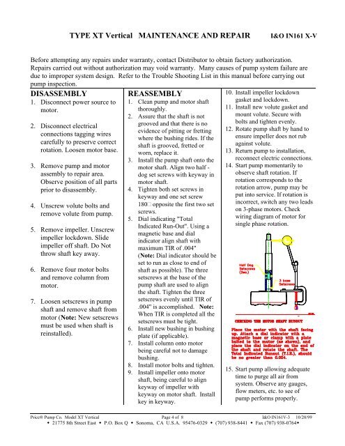
TYPE XT Vertical MAINTENANCE AND REPAIRI&O IN161 X-VBefore attempting any repairs under warranty, contact Distributor to obtain factory authorization.Repairs carried out without authorization may void warranty. Many causes of pump system failure aredue to improper system design. Refer to the Trouble Shooting List in this manual before carrying outpump inspection.DISASSEMBLY1. Disconnect power source tomotor.2. Disconnect electricalconnections tagging wirescarefully to preserve correctrotation. Loosen motor base.3. Remove pump <strong>and</strong> motorassembly to repair area.Observe position of all partsprior to disassembly.4. Unscrew volute bolts <strong>and</strong>remove volute from pump.5. Remove impeller. Unscrewimpeller lockdown. Slideimpeller off shaft. Do Notthrow shaft key away.6. Remove four motor bolts<strong>and</strong> remove column frommotor.7. Loosen setscrews in pumpshaft <strong>and</strong> remove shaft frommotor (Note: New setscrewsmust be used when shaft isreinstalled).REASSEMBLY1. Clean pump <strong>and</strong> motor shaftthoroughly.2. Assure that the shaft is notgrooved <strong>and</strong> that there is noevidence of pitting or frettingwhere the bushing rides. If theshaft is grooved, fretted orworn, replace it.3. Install the pump shaft onto themotor shaft. Align two half -dog set screws with keyway inmotor shaft.4. Tighten both set screws inkeyway <strong>and</strong> one set screw180° opposite the first two setscrews.5. Dial indicating "TotalIndicated Run-Out". Using amagnetic base <strong>and</strong> dialindicator align shaft withmaximum TIR of .004"(Note: Dial indicator should beset to run as close to end ofshaft as possible). The threesetscrews at the base of thepump shaft are used to alignthe shaft. Tighten the threesetscrews evenly until TIR of.004" is accomplished. Note:When TIR is completed all thesetscrews must be tight.6. Install new bushing in bushingplate (if applicable).7. Install column onto motorbeing careful not to damagebushing.8. Install motor bolts <strong>and</strong> tighten.9. Install impeller onto motorshaft, being careful to alignkeyway of impeller withkeyway on motor shaft. Installkey in keyway.10. Install impeller lockdowngasket <strong>and</strong> lockdown.11. Install new volute gasket <strong>and</strong>mount volute. Secure withbolts <strong>and</strong> tighten evenly.12. Rotate pump shaft by h<strong>and</strong> toensure impeller does not rubagainst volute.13. Return pump to installation,reconnect electric connections.14. Start pump momentarily toobserve shaft rotation. Ifrotation corresponds to therotation arrow, pump may beput into service. If rotation isincorrect, switch any two leadson 3-phase motors. Checkwiring diagram of motor forsingle phase rotation.15. Start pump allowing adequatetime to purge all air fromsystem. Observe any gauges,flow meters, etc. to see ofpump performs properly.Price® Pump Co. Model XT Vertical Page 4 of 8 I&O IN161V-3 10/20/99• 21775 8th Street East • P.O. Box Q • Sonoma, CA U.S.A. 95476-0329 • (707) 938-8441 • Fax (707) 938-0764•