EF Series Pumps Manual - Finish Thompson Inc.
EF Series Pumps Manual - Finish Thompson Inc.
EF Series Pumps Manual - Finish Thompson Inc.

You also want an ePaper? Increase the reach of your titles
YUMPU automatically turns print PDFs into web optimized ePapers that Google loves.
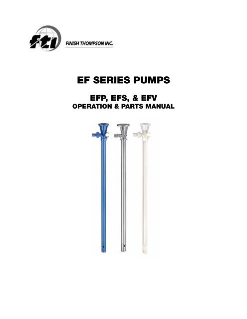
<strong>EF</strong> SERIES PUMPS<strong>EF</strong>P, <strong>EF</strong>S, & <strong>EF</strong>VOPERATION & PARTS MANUAL
EU Declaration of Conformity<strong>Finish</strong> <strong>Thompson</strong> <strong>Inc</strong>. hereby declares that the following machine(s) fully comply with theapplicable health and safety requirements as specified be the EC Directives listed.The product may not be taken into service until it has been established that the drive motorfor the Drum and Container Pump complies with the provisions of all relevant EC Directives.The complete product complies with the provisions of the EC Directive on machinery safetyprovided motors manufactured by <strong>Finish</strong> <strong>Thompson</strong> <strong>Inc</strong>. are used.This declaration is valid provided that the devices are fully assembled and no modificationsare made to these devices.Type of Device:Drum and Container Pump TubesModels:BTS – 40 EPPI/EPPS 15/27/40 <strong>EF</strong>P/<strong>EF</strong>V/<strong>EF</strong>S-16/27/40/48HVDP LR-27/40/48 HVDP HR-27/40/28 PFM-27/40/48/60PFP-15/27/40/48/60/72 PFS-27/40/48/60/72 PFV-27/40/48/60/72TBP-27/40/48 TBS-40 TTC/TTS -27/40/48STTS-40 TMS-40EC Directives:Machinery Safety (2006/42/EC)Applied Harmonized Standards:EN ISO 12100 Part 1EN ISO 12100 Part 2EN 809Manufacturer:<strong>Finish</strong> <strong>Thompson</strong> <strong>Inc</strong>.921 Greengarden RoadErie, Pennsylvania 16501-1591 U.S.ASigned,President_January 7, 2013Person(s) Authorized to Compile Technical File: Michael Smith Engineers LimitedOaks Road, Woking, SurreyGU21 6PH, UKTelephone: 01483 771871
IntroductionThis manual pertains to the <strong>EF</strong> <strong>Series</strong> drum pumps. <strong>Finish</strong> <strong>Thompson</strong> <strong>Inc</strong>. thanks you for choosing our products. Webelieve the use of our products will be fully satisfactory. When properly installed and operated, your <strong>Finish</strong> <strong>Thompson</strong>motor and pump will provide long, trouble-free service; therefore, please read this manual carefully before carryingout any operations on the pump/motor unit. Any use other than that described herein is considered incorrect; and,consequently, <strong>Finish</strong> <strong>Thompson</strong> <strong>Inc</strong>. shall not be held responsible for any damages to people or property. In case ofdoubt or enquiries, please reply to our Technical Service department directly at the following address:<strong>Finish</strong> <strong>Thompson</strong>, <strong>Inc</strong>.921 Greengarden Rd.Erie, PA 16501 U.S.A.Tel. 1-814-455-4478; Fax 1-814-455-8518www.finishthompson.com; fti@finishthompson.comIndexIntroduction/ Pump Specifications.................................................................................1Warranty, General Terms & Conditions...........................................................................2Safety...........................................................................................................................3Specifications & Dimensions.........................................................................................4Disassembly.................................................................................................................5-6Reassembly..................................................................................................................6-7Exploded Views – <strong>EF</strong>P/<strong>EF</strong>V/<strong>EF</strong>S Pump Tubes.................................................................8-9Pump Tube Spare Parts List..........................................................................................10-11Note: Repair instructions can be downloaded from our web site at www.finishthompson.com or contactTechnical Service at 1-800-888-3743.1
Warranty, General Terms & Conditions1. The following terms and conditions apply to the sale of machinery, components and related services and products, of <strong>Finish</strong><strong>Thompson</strong> <strong>Inc</strong>. (hereinafter “the products”)2. <strong>Finish</strong> <strong>Thompson</strong> <strong>Inc</strong>. (the manufacturer) warrants only that:a) its products are free of defects in material, design and workmanship at the time of original purchase;b) its products will function in accordance with <strong>Finish</strong> <strong>Thompson</strong> <strong>Inc</strong>. operation manuals; <strong>Finish</strong> <strong>Thompson</strong> <strong>Inc</strong>. does notguarantee that the product will meet the precise needs of the Customer, except for those purposes set out in any invitationto render documents or other documents specifically made available to <strong>Finish</strong> <strong>Thompson</strong> <strong>Inc</strong>. before entering into thisagreement;c) high quality materials are used in the construction of the pumps and that machining and assembly are carried out to thehighest standards. Except as expressly stated above, <strong>Finish</strong> <strong>Thompson</strong> <strong>Inc</strong>. makes no warranties, express or implied,concerning the products, including all warranties of fitness for a particular purpose.This warranty shall not be applicable in circumstances other than defects in material, design, and workmanship. In particularwarranty shall not cover the following:d) Periodic checks, maintenance, repair and replacement of parts due to normal wear and tear;e) Damage to the product resulting from:i. Tampering with, abuse or misuse, including but not limited to failure to use the product for its normal purposes asstated at the time of purchase or in accordance with <strong>Finish</strong> <strong>Thompson</strong>, <strong>Inc</strong>. instructions for use and maintenance of theproduct, or the installation or improper ventilation or use of the product in a manner inconsistent with the technical orsafety standard in force;ii.Repairs performed by non-authorized service workshop, or opening of the unit by non-authorized personnel, or use ofnon genuine <strong>Finish</strong> <strong>Thompson</strong> <strong>Inc</strong>. parts;iii. Accidents, force majeure or any cause beyond the control of <strong>Finish</strong> <strong>Thompson</strong> <strong>Inc</strong>., including but not limited to lightning,water, fire, earthquake, and public disturbances, etc.3. The warranty shall cover the replacement or repair of any part, which is documented to be faulty due to construction or assembling,with new or repaired parts free of charge delivered by <strong>Finish</strong> <strong>Thompson</strong>, <strong>Inc</strong>. Parts subjected to normal wear andtear shall not be covered by the warranty. <strong>Finish</strong> <strong>Thompson</strong>, <strong>Inc</strong>. shall decide as to whether the defective or faulty part shall bereplaced or repaired. Transportation charges are prepaid to <strong>Finish</strong> <strong>Thompson</strong>.4. The warranty of the products shall be valid for a period of 12 months from the date of delivery, under the condition that noticeof the alleged defect to the products or parts thereof be given to <strong>Finish</strong> <strong>Thompson</strong>, <strong>Inc</strong>. within the term of 8 days from thediscovery.5. Repair or replacement under the terms of this warranty shall not give a right to an extension to, or a new commencement of,the period of warranty. Repair or replacement under the terms of this warranty may be fulfilled with functionally equivalent reconditionedunits. <strong>Finish</strong> <strong>Thompson</strong> <strong>Inc</strong>. qualified personnel shall be solely entitled to carry out repair or replacement of faultyparts after careful examination of the motor. Faulty parts or components when replaced by <strong>Finish</strong> <strong>Thompson</strong> <strong>Inc</strong>. will becomethe property of <strong>Finish</strong> <strong>Thompson</strong> <strong>Inc</strong>. If this warranty does not apply, the purchaser shall bear all cost for labor, material andtransportation.6. <strong>Finish</strong> <strong>Thompson</strong> <strong>Inc</strong>. will not be liable on any claim, whether in contact, tort, or otherwise, for any indirect, special, incidental,or consequential damages, caused to the customer or to third parties, including loss of profits, process down time, transportationcosts, costs associated with replacement or substitution products, labor costs, installation or removal costs. In any andall events, manufacturer’s liability shall not exceed the purchase price of the product and/or accessories.7. Return Policy. Should you have any problems with this product, please contact the distributor in your area. The distributorwill determine if a return to the factory is necessary and will contact the factory for a Return Authorization Number. Otherwise,contact our Technical Service Hotline (1-800-888-3743) or e-mail techservice@finishthompson.com if you have any questionsregarding product operation or repair.2
1. IntroductionSafetyThis manual contains all the information needed for the correct installation, use and maintenance of your new <strong>Finish</strong> <strong>Thompson</strong>pump. It should be read and understood by all the personnel involved in installation, operating and servicing of the pump beforeit is started.2. Operator Qualification and TrainingThe personnel in charge of the installation, the operation, and the maintenance of the pump must be qualified and able to performthe operations described in this manual. <strong>Finish</strong> <strong>Thompson</strong>, <strong>Inc</strong>. shall not be held responsible for the training level ofpersonnel and for the fact that they are not fully aware of the contents of this manual.3. Safety InstructionsFOR YOUR OWN SAFETYB<strong>EF</strong>ORE using or servicing your pump, please make sure to wear the proper clothing, eye protection and follow standard safetyprocedures when handling corrosive or personally harmful materials.GENERAL DANGERNEVER use a plastic pump or an open, splash-proof, T<strong>EF</strong>C or non-ATEX motor when pumping or mixing flammable or combustiblematerial.ALWAYS use a Model <strong>EF</strong>S 316SS pump tube with Model S4 air motor and static protection kit with grounded discharge hose,P/N 107429, when pumping or mixing flammable or combustible material. Follow Assembly, Installation & Operating Instructionsfrom manual, P/N J102721, included with the static protection kit or it can be accessed online at www.finishthompson.com/downloads.ALWAYS use and store the pump and motor in an upright position.DANGER: POWER SUPPLYRefer to instructions in the appropriate motor Operation & Installation <strong>Manual</strong>.4. Noise LevelRefer to specifications in the appropriate motor Operation & Installation <strong>Manual</strong>.5. Modifications and Spare PartsAny changes concerning the service of the pump as originally purchased can be executed only after written approval from<strong>Finish</strong> <strong>Thompson</strong> <strong>Inc</strong>. It is recommended to use only genuine <strong>Finish</strong> <strong>Thompson</strong> <strong>Inc</strong>. spare parts and approved accessories. Theuse of non-original spare parts or non-approved accessories will void warranty and removes any responsibility on the manufacturer’sbehalf for any damage caused to people or things.6. CleaningIt is highly recommended to flush pumps with clean water or some other neutralizing fluid compatible with pump materialswhen done pumping or when switching chemicals.Hose & Cord Storage<strong>EF</strong>P & <strong>EF</strong>V model pumps have a built-in hose & cord clip. You can use these clips to store your hose and keep the plug off the floor,free of damage and corrosion. When selecting a discharge hose, you should use a 3/4" ID reinforced chemically compatible hosesecured with a stainless steel hose clamp. See figures A and B below.Figure AFigure B3
PUMP SPECIFICATIONSMODEL <strong>EF</strong>P MODEL <strong>EF</strong>V MODEL <strong>EF</strong>SOuter Tube Diameter 1-1/4” (3.22 cm) 1-5/16” (3.3 cm) 1-1/4” (3.2 cm)Discharge Spout 3/4” Barb 3/4” Barb 3/4” BarbDischarge Thread 1” NPT 1” NPT OptionalMax. Specific Gravity 1.6 1.6 1.6Max. Viscosity 300 cP 300 cP 300 cPMin./ Max. Fluid TemperaturePolypropylene, FKM, PTFE, ETFE,Wetted Materials316 SS*<strong>EF</strong>V-54 Maximum Temperature = 150° F (66° C)0° F Min. to 150° F Max. 0° F Min. to 160° F* Max. 0° F Min. to 212° F Max.(-18° C Min. to 66° C Max.) (-18° C Min. to 71° C* Max.) (-18° C Min. to 100° C Max.)Pure Polypropylene, PVDF, FKM,PTFE, ETFE, Alloy 625316 SS, FKM, PTFE, ETFE4
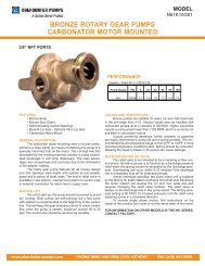
DISASSEMBLY & REASSEMBLY INSTRUCTIONSDisassembly1. Prior to disassembly - remove the motor and discharge tubing.2. Diffuser Removal - For <strong>EF</strong>P & <strong>EF</strong>V Models – When looking at the bottom of thepump, loosen the diffuser (item 17) by turning it clockwise (left-hand thread) 2-3 turnsor until it touches the impeller (item 18). See figure 1.3. Impeller Removal - Using a flat-head screwdriver, unthread the impeller (item 18)by turning it counter clockwise (right-hand thread). Hold the coupling insert andcoupling (items 1 & 2) in one hand, and unthread with the other. Note: If the shaftunthreads from the coupling, use a pliers to hold the top of the shaft. Care should betaken to not damage the shaft threads. For longer 40” and 48” pump lengths, twopeople may be required to hold the shaft and unthread the impeller. See figure 2.Figure 14. Unthread the impeller roughly 10 turns or until loose.5. Now finish unthreading the diffuser. If the impeller is loose, it will come off with the diffuser.Figure 26. To remove the impeller from the diffuser, shake it until it engages the impeller guard inside the diffuser, and turn itcounter clockwise with a flat head screwdriver or your fingers.7. Diffuser Removal - For <strong>EF</strong>S Models - Unthread the diffuser cover (item 19). Turn it clockwise (left-hand thread).Unthread the impeller (item 18) turning it counter clockwise (right hand thread) using a flat-head screwdriver or handwhile holding the coupling insert and coupling (items 1 & 2) with the other hand. Note: If the shaft unthreads from thecoupling, use a pliers to hold the top of the shaft. Care should be taken to not damage the shaft threads. For longer40” and 48” pump lengths, two people may be required to hold the shaft and unthread the impeller. Unthread the diffuser(item 17) turning it clockwise (left-hand thread).8. Shaft Removal - for all models - To remove the shaft (item 4), tap the bottom of the shaft on a piece of wood or plasticand push the shaft up and out of the head (item 6). Grab the half coupling or bearing and pull the shaft assemblystraight out of the head. Note: Take care to not bend the shaft. Important - The shaft should only be removed if thebearing is frozen and needs to be replaced.9. Outer Tube Removal - For <strong>EF</strong>P & <strong>EF</strong>V Models - Remove the outer tube (item 16). Hold the head (item 6) in one handand with the other hand, turn the outer tube clockwise (left-hand thread). When completely unthreaded, pull the outertube away from the head exposing the inner tube and center support (items 13 & 14).10. Inner Tube & Center Support Removal - To remove the inner tube and center support,turn the inner tube to unseat the o-rings (item 12) and then pull the inner tubeaway from the head.11. Shaft Sleeve Removal - The shaft sleeve (item 15) will drop out of the inner tube byholding it in a vertical position and turning.12. Center Support Removal - 40” and 48” lengths only - If the center support (item 14)needs to be replaced, it can be removed by spreading open the fingers and disengagingit from the inner tube. See figure 3.Figure 35
13. Inner Tube & Shaft Sleeve Removal - The outer tube and head for <strong>EF</strong>S models arewelded together. To remove the inner tube and shaft sleeve (items 13 & 15 indicatedon the Exploded View on pg. 8-9), hold the outer tube and head assembly in a verticalposition, and the shaft sleeve will fall out. To remove the inner tube, “pretend” tohit the bottom of the pump on the floor but stop before it actually hits. This motionwill allow the weight of the inner tube to release the o-rings, and it will drop out ofthe bottom of the pump. It is recommended to do this over a soft surface to preventdamaging the inner tube as it drops out of the pump.14. Seal Removal - To remove the seal (item 5) from the head (item 6 or item 16 for <strong>EF</strong>S),use a hook tool, available at most hardware stores, to pull the seal out from the top ofthe head. Take care not to damage the seal seat area. See figure 4. Note: The sealshould be replaced if worn or the bearing is failing or frozen.Figure 4Reassembly1. Seal Installation for <strong>EF</strong>P & <strong>EF</strong>V models - Take the head (item 6), and for <strong>EF</strong>S models take the outer tube with head(item 16), and install a new seal (item 5). Insert the open part of the seal into the lower bore of the head. See figure 5.Use a 3/8” (9.5 mm) dowel to press and seat the seal into place. Seal sits slightly below the surface. See figure 6.Figure 5Figure 62. Reinstall the half coupling, bearing and shaft (items 2, 3 & 4 indicated on the Exploded View on pg. 8-9) as anassembly into the head. If the bearing needs to be replaced it is recommended to purchase a new shaft, bearing andhalf coupling assembly because the <strong>EF</strong> <strong>Series</strong> shaft can be damaged when removing or installing the bearing.3. Shaft Installation - Slide the shaft down through the seal until the bearingengages the bearing bore in the head. Use any size dowel under 1”(25.4 mm) indiameter and press the half coupling, bearing and shaft into place using an arborpress or by lightly tapping with a soft mallet. Note: Do not use excessive force.Unthread the half coupling counter clockwise (right hand thread) to verify that thebearing is seated properly. See figure 7. Reinstall the half coupling.4. Inner Tube, Center Support & Shaft Sleeve Installation - for all models -Figure 7Reinstall the inner tube, center support (if used) and shaft sleeve (items 13, 14 &15). Slide the shaft sleeve onto the shaft. The shaft sleeve is self-positioning soslide it up as far as it will go on the shaft. Reinstall the inner tube with center support (if used) over the shaft andshaft sleeve. The double o-ring side seats up into the head with a slight twisting motion. Make sure the inner tubeis seated properly. The bottom of the inner tube will be flush with the bottom of the outer tube when properly seated.6
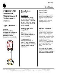
5. Outer Tube Installation - for <strong>EF</strong>P & <strong>EF</strong>V models - Install the outer tube(item 16). Make sure the center support (if used) is installed correctly onthe inner tube. The center support has a slight taper that allows the outertube to slide easily over it.See figure 8. Slide the outer tube with external threads over the shaft,shaft sleeve, inner tube and center support (if used) up into the head (item6). Turn the outer tube counter clockwise (left hand thread) to tighten it intothe head. Hand tighten. Figure 86. Diffuser Installation - for all models - Install the diffuser (item 17) onto thebottom of the outer tube. Insert the shaft through the small support openingon the diffuser. See figure 9. The small support opening will insert up insidethe inner tube (item 13). With a slight push and turn, thread the diffuser intothe outer tube (item 16) turning counter clockwise (left hand thread). <strong>EF</strong>Pand <strong>EF</strong>V models - only tighten the diffuser halfway or 3-4 turns. See figure10. Insert the impeller (item 18) into the bottom of the diffuser. With a slightpush and turn the impeller should twist through the impeller guards and engagethe shaft threads. Use a flathead screwdriver to tighten the impeller tothe shaft turning clockwise (right hand thread). See figure 11. Hold the halfFigure 9coupling (item 2) in one hand while turning the impeller with the other.Hand tighten. Once the impeller is tightened, finish tightening the diffuser turning counter clockwise (left hand thread).Hand tighten.Figure 10 Figure 117. For <strong>EF</strong>S Models - Thread the diffuser (item 17) completely onto the bottom of the outer tube (item 16). Thread theimpeller onto the shaft by hand. While holding the half coupling with the other hand, turn the impeller clockwise(right hand thread). See figure 12. Install the diffuser cover (item 19), <strong>EF</strong>S models only, onto the diffuser turningcounter clockwise (left hand thread). Hand Tighten.Figure 127
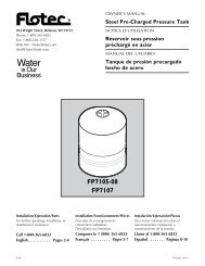
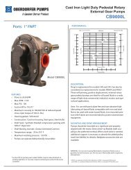
<strong>EF</strong>P & <strong>EF</strong>V SERIES PUMPEXPLODED VIEW8
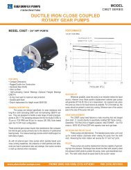
<strong>EF</strong>S SERIES PUMPEXPLODED VIEW9
PUMP SPARE PARTS LISTITEM QTY DESCRIPTIONPART NUMBERMODEL <strong>EF</strong>P MODEL <strong>EF</strong>V MODEL <strong>EF</strong>S*1 1COUPLING INSERTJ103422 J103422 J1034222 1COUPLING HALF107300 107300 1073003 1BEARINGAVAILABLE ONLY AS PART OF COUPLING HALF, BEARING & SHAFT ASSEMBLY4 1SHAFTAVAILABLE ONLY AS PART OF COUPLING HALF, BEARING & SHAFT ASSEMBLYCOUPLING HALF, BEARING & SHAFT ASSEMBLYCOUPLING HALF, BEARING & SHAFT - 16” 107589-1 107590-1 107589-1*2,3,4 1COUPLING HALF, BEARING & SHAFT - 27” 107589-2 107590-2 107589-2COUPLING HALF, BEARING & SHAFT - 40” 107589-3 107590-3 107589-3COUPLING HALF, BEARING & SHAFT - 48” 107589-4 107590-4 107589-4COUPLING HALF, BEARING & SHAFT - 54” 107589-5 107590-5 N/A*5 1SEALFKM 107297 107297 107297PUMP HEAD6 1 POLYPROPYLENE 107071-1 N/A N/APVDF N/A 107071-2 N/A7 4FLAT WASHERSTAINLESS STEEL J103601 J103601 N/A8 4HI-LOW SCREWSTAINLESS STEEL J101020 J101020 J101020SPOUT O-RING*9 1 FKM (STANDARD) 106155 106155 N/AEPDM 106154 106154 N/A10 1SPOUTPOLYPROPYLENE 107072-1 N/A N/APVDF N/A 107072-2 N/A11 1NUTPOLYPROPYLENE 107069-1 N/A N/APVDF N/A 107069-2 N/A*12 2INNER TUBE O-RINGFKM (STANDARD) 107299 107299 107299EPDM 107729 107729 107729INNER TUBE16” 107294-1 107294-1 107578-113 127” 107294-2 107294-2 107578-240” 107294-3 107294-3 107578-348” 107294-4 107294-4 107578-454” 107294-5 107294-5 N/A*14 1CENTER SUPPORTT<strong>EF</strong>ZEL ® (ETFE) - 40” & 48” LENGTHS ONLY 107068 107068 N/ASHAFT SLEEVE - PTFE16” 107293-1 107293-1 107293-1*15 127” 107293-2 107293-2 107293-240” 107293-3 107293-3 107293-348” 107293-4 107293-4 107293-454” 107293-5 107293-5 N/AOUTER TUBE (MODEL <strong>EF</strong>S INCLUDES PUMP HEAD)16” 107295-1 107295-2 107580-116 127” 107295-3 107295-4 107580-240” 107295-5 107295-6 107580-348” 107295-7 107295-8 107580-454” 107295-9 107295-10 N/ADIFFUSER*17 1POLYPROPYLENE 107070-1 N/A N/APVDF N/A 107070-2 N/A316 STAINLESS STEEL (W/ PTFE BUSHING) N/A N/A 108115N/A = Not Applicable10
ITEM QTY DESCRIPTIONPART NUMBERMODEL <strong>EF</strong>P MODEL <strong>EF</strong>V MODEL <strong>EF</strong>S*18 1IMPELLERPOLYPROPYLENE 107067-1 N/A N/AT<strong>EF</strong>ZEL ® (ETFE) N/A 107067-2 107067-219 1DIFFUSER COVER316 STAINLESS STEEL N/A N/A 10758420 1DIFFUSER BUSHINGPTFE N/A N/A 107585DIFFUSER O-RING*21 1 FKM (STANDARD) N/A N/A 107586EPDM N/A N/A 10776622 1GROUNDING SCREWBRASS N/A N/A J10082223 1N/A = Not ApplicableGROUNDING SCREW LOCKWASHERBRASS N/A N/A J100823* Recommended Spare PartsTefzel ® is a registered trademark of the DuPont Company.Service 1-800-888-3743P/N 107317, Rev7, 10-12-12