Technical Service Bulletin - New York Bus Sales
Technical Service Bulletin - New York Bus Sales
Technical Service Bulletin - New York Bus Sales

You also want an ePaper? Increase the reach of your titles
YUMPU automatically turns print PDFs into web optimized ePapers that Google loves.
Source: Leece-Neville Heavy Duty Systems Division -Arcade, NY USADate: September 29, 2005Subject: School <strong>Bus</strong> Application Guide<strong>Bulletin</strong> No: TSB-1025Models: School <strong>Bus</strong> Models (see chart, last page)<strong>Technical</strong> <strong>Service</strong><strong>Bulletin</strong>We all know the first and most important thing to consider when it comes to a school bus is‘Safety’. The second most important item would be ‘reliability’ with minimal long term financial liability toits owner or operators.Below, one will find some helpful tips to ensure that your ‘School <strong>Bus</strong>’ has the correct ‘ALTERNATOR’and how to determine if appropriate ‘CABLING’ is in place that will connect the required alternator to theelectrical system, ensuring ‘Safety’ and ‘Reliability’.Today’s school buses have a very high amperage demand. The amperage requirements forthe engine, transmission, high intensity lights, radios, door controls, wheel chair lifts, heaters, airconditioning, monitoring devices, drive line retarders, etc. are increasing year by year. Chances area 160 amp alternator that performed well in 2000 will not be appropriate in 2005 due to increasedamperage demands. *Note all of the electrical accessories which require additional amperageare not always installed by the manufacture of the bus. If the ‘ALTERNATOR’ and ‘CABLING’ is notappropriately specified or upgraded to manage the additional amperage requirements this will require thebatteries be utilized for purposes which they were not intended, contributing to progressive damage of thebatteries and other components in the electrical system.The Battery: A reservoir of chemical electrical power. Its primary purpose is to provide theelectrical energy needed for engine cranking.Once the engine has been started, the purpose of the battery is complete. After the engine hasbeen started the school bus amperage requirements should be managed by the alternator. This ensuresbatteries are charged properly and are healthy for the next time they are needed for engine cranking.Many of today’s school buses have an alternator which is not appropriate. The result; amperagerequired to manage the vast electrical accessories is consumed from the batteries depleting the batteriesstate of charge.Did you know that a common flooded lead acid battery can absorb as much as 10 to 20% of itsCCA rating in amperage at 75% state of capacity or below? True. If the incorrect alternator is utilized,although the batteries will have enough energy to start the engine and assist in maintaining the neededamperage of the school bus, they actually contribute to an even greater amperage requirement.A school bus spends most of its operational time with either the engine idling or at very slowground speeds. Knowing this; if your school bus has the incorrect alternator and amperage is beingconsumed from the batteries during operation. Chances are at the end of the day the batteries have notbeen charged appropriately. This contributes to premature alternator, starter and battery failures.Important: The information contained in this bulletin is intended for use by trained, professional technicians who have the proper tools, equipment, and training to performthe required maintenance described above. This information is NOT intended for ‘do-it-yourselfers’, and you should not assume that this information applies to yourequipment. If you have any questions regarding this information please visit our website at www.prestolite.com, or contact our technical service department at:Leece-Neville Heavy Duty Systems400 Main StreetArcade, NY 14009Page 1 of 7Phone: (866) 288-9853Fax: (866) 288-9853webmail@prestolite.com
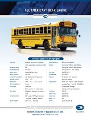
<strong>Bulletin</strong> No.:TSB-1025<strong>Technical</strong> <strong>Service</strong><strong>Bulletin</strong>The Alternator: The total output rating of the alternator normally leads one to inappropriatelychoose the correct alternator for its application. It’s not the ‘total’ amperage output capability that isimportant when choosing the correct alternator. It is the amount of amperage the alternator canproduce at its nominal speed of operation for a school bus that is important.Since we have stated a school bus spends most of its time idling or at slow operational speeds letstake a closer look. A typical school bus equipped with standard D.O.T. requirements has the minimal needof 65 amps and a maximum need of 115 amps depending on accessories each individual operator maychoose. However a typical school bus with basic Air Conditioning or 4 under seat Heaters has an averageamperage requirement of 136 amps and a maximum need of 165 amps depending on accessories eachindividual operator may choose. Some have minimal requirements of 174 amps and maximum amperagerequirements as high as 225 amps.Performance by application: When recommending an alternator for a specific application, a base linecriterion is established by never allowing the required amperage demand of the vehicle to exceed 80%of the alternators output ability. Why? Thermal degradation “heat” is known to contribute to the loss ofalternator output efficiency by as much as 15%. The margin of efficiency remaining of 5% is utilized tomaintain the batteries state of charge; if and when load demands at idle, intermittently exceed that of thealternators output ability at a set rotor speed.Such as; when the engine is idling and a wheel chair lift is in operation for passenger loading or offloading. During this time of operation amperage is being consumed from the batteries by the lift and thebatteries state of charge is reduced. When lift operation is complete, the alternator will have the abilityto replenish the batteries state of charge enabling long battery life and maximum state of charge in thebattery without increasing the engine speed. The battery is to be utilized when the highest amperagedemand is required for engine startup and only to be utilized intermittently in its application when optionalloads exceed that of the alternator for a short period of time. By default the nominal or constants speed ofthe alternator in the school bus vocation is considered to range from 1850 to 2400 RPM.Determine the amperage requirement: It is very important that you determine your nominal requiredamperage before choosing the alternator for your bus.To determine this, utilize a DC Clamp on amperage instrument and follow the steps below.* Always ensure that the batteries state of charge is greater than 12.45 volts with a volt meter. If thebatteries have been charged with a battery charger or the alternator within 24 hours of this test the batteries surfacecharge must be removed before proceeding with this test as it will be inaccurate. To remove the surface charge,simply turn the headlamps of the bus on and select “high beam” for 5 minutes. After 5 minutes turn the head lampsoff, allow the batteries to recover for 1 minute and measure the true state of battery charge with a voltmeter.Remember the battery voltage must be greater than 12.45 volts for this test to be accurate. If it is necessaryrecharge the batteries with a battery charger before proceeding with this test.A. Start the engine of the bus and operate it at idle speed.B. Simulate the operation. Turn on electrical accessories that would normally be operated whenthe bus is en-route off loading or on loading passengers. (If equipped with a wheel chair lift, donot take it into consideration at this point.)Important: The information contained in this bulletin is intended for use by trained, professional technicians who have the proper tools, equipment, and training to performthe required maintenance described above. This information is NOT intended for ‘do-it-yourselfers’, and you should not assume that this information applies to yourequipment. If you have any questions regarding this information please visit our website at www.prestolite.com, or contact our technical service department at:Leece-Neville Heavy Duty Systems400 Main StreetArcade, NY 14009Page 2 of 7Phone: (866) 288-9853Fax: (866) 288-9853webmail@prestolite.com
<strong>Bulletin</strong> No.:TSB-1025<strong>Technical</strong> <strong>Service</strong><strong>Bulletin</strong>C. Attach DC Amperage Clamp onto Positive alternator output cable and record the total amperageoutput. Ensure that the arrow of the DC Amperage clamp is facing away from the alternator.Record Amperage output ________.D. At the battery location of the bus. Locate all cables / wires attached to the (+) batteryterminals.1. Clamp each positive cable/wires individually ensuring the arrow of the DC AmperageClamp is pointing to the (+) battery post. If any cable/wire clamped indicates a positiveamperage reading, record each positive number. Total and Record all positive amperagereadings. Total positive amperage recorded____.2. If any of the positive cable/wires has negative amperage reading with the arrow ofthe DC amperage clamp pointing toward the positive battery post. Record the negativeamperage reading. Total of negative amperage readings_____3. Subtract the total negative amperage reading of all cables recorded at the batteries fromthe total positive amperage reading of all cables recorded at the battery.Negative amperage total _____ (-) Positive amperage total ______ = (___).Example: Negative amperage total = - 47 (subtract) Positive amperage total 31= (-16)• If the total is a negative amperage reading this sum will be utilized in step F. If thetotal is a positive amperage reading or zero the equipped alternator is sufficient foryour bus.E. Add values recorded in Step D ___ + Sum of Step E.3. ___ = Total Amperagerequirement _____. *See step G if your bus is equipped with an electric drive lineretarder.F. Turn off all electrical accessories and stop engine. You have now determined the nominalamperage requirement of the School <strong>Bus</strong>. Below in this document one will find how toappropriately determine the needed alternator for you amperage requirement.G. If your bus is equipped with an electric drive line retarder you will need to measure the maximumamperage requirement of the drive line retarder while operating it in the highest applied brake positionand record the amperage requirement. 25% of this maximum amperage value will then have to be addedto the above determined total amperage value. This value will then be utilized in the following step.H. *The above total amperage should not exceed the alternators output capability at 2000 RPM ofthe alternator.*** Repeat the above procedure simulating ‘winter’ operation and ‘summer’ operation. The valuerecorded for summer or winter operation will be different. The largest number should be utilizedwhen sizing the appropriate alternator for your School <strong>Bus</strong>.Important: The information contained in this bulletin is intended for use by trained, professional technicians who have the proper tools, equipment, and training to performthe required maintenance described above. This information is NOT intended for ‘do-it-yourselfers’, and you should not assume that this information applies to yourequipment. If you have any questions regarding this information please visit our website at www.prestolite.com, or contact our technical service department at:Leece-Neville Heavy Duty Systems400 Main StreetArcade, NY 14009Page 3 of 7Phone: (866) 288-9853Fax: (866) 288-9853webmail@prestolite.com
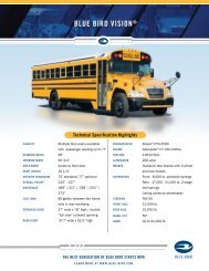
<strong>Bulletin</strong> No.:TSB-1025<strong>Technical</strong> <strong>Service</strong><strong>Bulletin</strong>Now let’s look at the typical 160 amp alternator amperage output capability. As we stated the nominal orconstants speed of the alternator in the school bus application would be within a range of 1850 to 2400 RPM.One can see that the 160 amp alternator in hot run conditions can produce an average of 95 amps in thisrange of operation. Well below what would be required for the average school bus today “if” equipped with AirConditioning or with three or four under-seat Heaters.160 amp alternator performance curveThe typical School <strong>Bus</strong> today would require a 185 amp alternator to ensure that basic amperage requirementsare exceeded and healthy batteries are maintained and would not be adequate if air conditioning were installed in allcases.If you intend to install air-conditioning or under seat heaters in excess of two, a minimum a 200 ampalternator would be required; however in most cases a 270 amp alternator would be required due to the neededamperage at engine idle conditions. Actual alternator output performance charts can be obtained through your localdistributor or directly from Leece Neville. (see chart on last page)Alternator Output cable size: The standard output cabling and circuits installed on most standardschool bus chassis if not originally equipped with a 200 amp alternator or larger at the factory would beinappropriate for any alternator larger than 175 amps that would be installed after production. Why? Themost important item to be considered for an alternator to have a long reliable life is not to exceed .25volts of resistance in each output circuit individually when applying a load to the circuit equal to 75% ofthe alternators rated output capacity. If equipped with inappropriate cabling “to small in size” this wouldrender the same results of an inadequately sized alternator resulting in short or less than expectedreliability.Below one will find an appropriate cable sizing worksheet. However some quick tips that may save youtime when accessing the existing cabling on your school bus chassis.Important: The information contained in this bulletin is intended for use by trained, professional technicians who have the proper tools, equipment, and training to performthe required maintenance described above. This information is NOT intended for ‘do-it-yourselfers’, and you should not assume that this information applies to yourequipment. If you have any questions regarding this information please visit our website at www.prestolite.com, or contact our technical service department at:Leece-Neville Heavy Duty Systems400 Main StreetArcade, NY 14009Page 4 of 7Phone: (866) 288-9853Fax: (866) 288-9853webmail@prestolite.com
<strong>Bulletin</strong> No.:TSB-1025<strong>Technical</strong> <strong>Service</strong><strong>Bulletin</strong>Negative Circuit: alternators 200 amps or larger in total output rating are designed withCase ground. Due to this, to circumvent oversights and issues associated to electrolysis and save time,one can simply utilize the existing ground cable attached to the existing alternator. However one wouldneed to locate - remove - and replace the existing ground/earth cable which leads from the starter/cranking motor or the chassis frame rail to the engine block. This cable should be replaced with aminimum 1/0 or 1 gauge cable.Positive Circuit: In many cases the existing positive cable and circuits of a School <strong>Bus</strong> chassis as built bythe manufacture is also inappropriate for alternators larger than 175 amps. This is due to the actual cablesize being inadequate and some also incorporate protective fusible devices that will have to be upgradedto a larger amperage requirement. Examples of these fusible devices are fusible wire/cable links, megafuses and circuit breakers both thermal type and reset type. The entire circuit must be upgraded. Whenupgrading/replacing this circuit a fusible device such as a mega-fuse should be incorporated into the newcircuit if it was originally equipped with one. At minimum a 1/0 or 1 gauge cable should be utilized andthe fused device selected should exceed 5% but not exceed 25% of the total rated output capacity of thealternator. In all applications the fused device must be mounted and incorporate a protective coating of allconnection points. One should also consider obtaining the appropriate “complete circuit components” fromthe original manufacture of the applicable bus chassis which would incorporate the appropriate fusibledevice sized for the alternator you have determined appropriate for the application.Recommend Cable sizing guide:Amperage Cable Length Cable Size* Some chassis manufactures utilize cabling of different type and/or size. However due to the constructionof the cable and the type of wire, a smaller outside wire diameter or size may be applicable. Refer to ourtechnical training manual Section 3 Article 4 “Cable Test” on our web site www.prestolite.com for propertesting instructions to validate existing or recommended circuit or cable/wire type.Important: The information contained in this bulletin is intended for use by trained, professional technicians who have the proper tools, equipment, and training to performthe required maintenance described above. This information is NOT intended for ‘do-it-yourselfers’, and you should not assume that this information applies to yourequipment. If you have any questions regarding this information please visit our website at www.prestolite.com, or contact our technical service department at:Leece-Neville Heavy Duty Systems400 Main StreetArcade, NY 14009Page 5 of 7Phone: (866) 288-9853Fax: (866) 288-9853webmail@prestolite.com
<strong>Bulletin</strong> No.:TSB-1025<strong>Technical</strong> <strong>Service</strong><strong>Bulletin</strong>Operational tip: When appropriate “if” the school bus may be required to operate long periods of time with theengine idling. The operator of the bus should always utilize a high idle device to increase the engine speed toapproximately 1100 RPM. This would be periods of time when pre-delivery inspection is taking place, wheel chair liftoperation is required or pre-heating / cooling the interior of bus with the heaters or air conditioning. This will ensurelong reliable life of the alternator and electrical components of your school bus.Specification tip: When considering the purchase of a new school bus, it is important to write into the specification,the effects added electrical accessories by a third party installers, add to the amperage demands of the chargingcircuit and require improvements associated.Important: The information contained in this bulletin is intended for use by trained, professional technicians who have the proper tools, equipment, and training to performthe required maintenance described above. This information is NOT intended for ‘do-it-yourselfers’, and you should not assume that this information applies to yourequipment. If you have any questions regarding this information please visit our website at www.prestolite.com, or contact our technical service department at:Leece-Neville Heavy Duty Systems400 Main StreetArcade, NY 14009Page 6 of 7Phone: (866) 288-9853Fax: (866) 288-9853webmail@prestolite.com
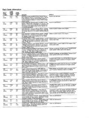
<strong>Bulletin</strong> No.:TSB-1025<strong>Technical</strong> <strong>Service</strong><strong>Bulletin</strong>Below is a guide that will assist in choosing the appropriate alternator for common optional equipment utilized in theschool bus industry.Minimum Amperage Application Part Number Type of Excitation Notes4833LGH Self Excite J-180 MOUNT185Any school bus with NO A/C. Can bewith or without a wheelchair lift.4836LGHSelf Excite4939PGH Self Excite PAD MOUNTSame as 4833LGH but withreverse POS and NEG terminals(Cummins B and C engines)200Any school bus with ONE A/C. Canbe with or without a wheelchair lift. Anyschool bus without A/C but that doeshave an electromagnetic brake retarder.4860JB Ignition Excite J-180 MOUNT4863JB Self Excite J-180 MOUNT4940PA Ignition Excite PAD MOUNT4951PASelf ExcitePAD MOUNT270320Any school bus with TWO A/C. Canbe with or without a wheelchair lift.Any school bus with ONE A/C AND anelectromagnetic brake retarder.Any school bus with TWO A/C unitsand either a DASH A/C unit or a THIRDA/C unit. Can be with or without awheelchair lift. Any school bus withTWO A/C units AND an electromagneticbrake retarder.4867JB Self Excite J-180 MOUNT4870JB Ignition Excite J-180 MOUNT4942PA Ignition Excite PAD MOUNT4944PA Self Excite PAD MOUNT4947PA Ignition Excite PAD MOUNT4949PASelf ExcitePAD MOUNT4890JB Self Excite J-180 MOUNT4962PASelf ExcitePAD MOUNTThese are our minimum recommendations for amperage outputs. This will eliminate all of the guess work associated with trying to match upspecifi c pulley to engine ratios.Please keep in mind that when specifying alternators for school buses with CNG (compressed natural gas) or LNG (liquid natural gas) engines,either forward engine or rear engine, we recommend using REMOTE MOUNTED REGULATORS. It is recommended that all forward enginetransit busses be equipped with REMOTE MOUNTED REGULATORS. Although recommended by Leece-Neville, it is at the discretion of theOriginal Equipment <strong>Bus</strong> manufacture to make this option available. If you choose to purchase these parts, contact Leece-Neville at 866-288-9853for applicable part numbers to make this change by alternator product modelWe defi ne A/C as a unit having one evaporator and one condenser. If the bus is equipped with a main rear evaporator system and a slave dashA/C, we would consider that a TWO A/C system, even though they share the same condenser.Important: The information contained in this bulletin is intended for use by trained, professional technicians who have the proper tools, equipment, and training to performthe required maintenance described above. This information is NOT intended for ‘do-it-yourselfers’, and you should not assume that this information applies to yourequipment. If you have any questions regarding this information please visit our website at www.prestolite.com, or contact our technical service department at:Leece-Neville Heavy Duty Systems400 Main StreetArcade, NY 14009Page 7 of 7Phone: (866) 288-9853Fax: (866) 288-9853webmail@prestolite.com