20 Terra et Aqua | Number 110 | March 2008<strong>The</strong>se findings were adopted as the startingpoint for two successive TASS field trialscarried out in Bremerhaven (June 2006) andRotterdam (May 2007). Both are describedbelow.TASS FIELD TRIAL BREMERHAVEN(2006)Design of field trialAs a continuation of the Rotterdam (2002)field trial, experiments were carried out inBremerhaven with the specific objective toarrive at a robust technique to collectrepresentative overflow samples duringdredging. As the use of sampling deviceson the rim of the overflow had proven tobe non-successful, it was recognizedsamples should be taken from within theoverflow with the help of a suction-typedevice. This involved two challenges.<strong>The</strong> technical challenge was to design asampling system which is robust enough towithstand the hostile hydrodynamicenvironment in the overflow and flexibleenough to take samples at various locationsand elevations within the overflow. Thissystem is described below. <strong>The</strong> theoreticalchallenge was to make sure that overflowsamples taken from a single point wererepresentative for sediment concentrationsacross the entire overflow cross-section.In other words, the samples should betaken from an area where the sedimentconcentration is uniformly distributed overthe overflow cross-section.<strong>The</strong> latter question was addressed bymeans of a theoretical analysis of mixingprocesses in the overflow (Svasek, 2006).<strong>The</strong> stages considered include the inflow,Figure 5. Location of theBremerhaven test site.supercritical flow over the rim, a free fallphase followed by a plunging jet, decayingturbulence in the pipe, uniform pipe flowand the outflow (Figure 4a). Based onsimple hydronamic rules and a fewconservative assumptions, it was found thatfor an open (i.e. non-drowned) overflow,samples could reliably be taken from anarea between 3 times the pipe diameterbelow the water surface and 1 pipediameter above the bottom end of theoverflow (Figure 4b). Moreover, since thepresence of air bubbles adversely affectsthe performance of the sampling pumps,it was recommended to locate the pumpsas deep as possible. <strong>The</strong> theoretical analysisdid not reveal a preferred horizontalposition within the overflow cross-section.During the field trial, dedicated experimentswere carried out to verify the feasibility ofthe submerged pump sampling system andthe representativeness of the samplestaken. <strong>The</strong> latter involved high-frequencysampling (typically twice per minute) in asingle point, repetitive sampling at two tothree different locations across the overflowcross-section (fixed elevation) and repetitivesampling at different elevations over a2.5 m range.Field measurements<strong>The</strong> Bremerhaven field trial was carried outbetween June 8 to 13 around the trailingsuction hopper dredger Cornelia, whichwas built in 1981, has two suction pipesand a hopper capacity of 6360 m 3 .During the measurement period she wasdredging sand in the harbour entrancechannel for the construction of a newcontainer terminal CT4. <strong>The</strong> site (Figure 5)is characterised by a tidal range of 3-4 m,significant tidal flow velocities (up to about2 m/s) and fine sand. Being located withinthe Weser estuary, the entrance channel issomewhat sheltered from direct waveaction.For the purpose of this field trial, anoverflow sampling system was developedand mounted in the overflow of theCornelia (Figure 6). <strong>The</strong> system consistedof a suction tube (Figure 6a) which wasconnected to two sub-merged pumps(Ircem DA 12M), mounted in series, witha maximum head of 10.4 m each.<strong>The</strong> suction device could be rotated arounda vertical axis to enable sampling fromdifferent locations over the cross-section.<strong>The</strong> whole system was mounted on avertical plate (Figure 6b) which could bemoved up and down the overflow, so thatsamples could be taken at differentelevations. Samples were collected by fillingbottles (Figure 6c) of known weight andvolume, which were weighted onboard todetermine sediment concentrations.To obtain in-situ flow velocities, a MarshMcBirney single axis current sensor wasmounted near the suction mouth(Figure 6a). Finally, a CTD diver ofVan Essen was used to measure salinity,temperature and conductivity throughoutthe experiments.<strong>The</strong> Bremerhaven field trial yielded a totalnumber of eight successful experiments,two of which were carried out duringmaintenance dredging of muddy materialin front of the existing container terminaland the other six during offshore sandmining for the construction of the newterminal.ResultsFigure 7 shows example time series ofsediment concentrations (a, b) and flowvelocities (c, d) measured in the overflow,representing a fine sand run (Trip 158,panel a, c) in the offshore borrow area anda maintenance run with muddy sediment(Trip 157, panel b, d) in front of theexisting terminal. <strong>The</strong> upper panels alsoshow time series of the hopper volume forboth trips, to indicate when the overflowwas being operated.
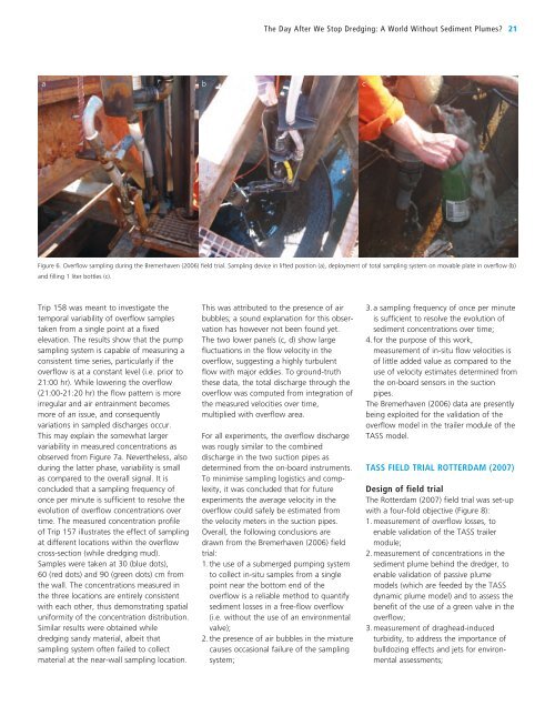
<strong>The</strong> Day After We Stop <strong>Dredging</strong>: A World Without Sediment Plumes? 21abcFigure 6. Overflow sampling during the Bremerhaven (2006) field trial. Sampling device in lifted position (a), deployment of total sampling system on movable plate in overflow (b)and filling 1 liter bottles (c).Trip 158 was meant to investigate thetemporal variability of overflow samplestaken from a single point at a fixedelevation. <strong>The</strong> results show that the pumpsampling system is capable of measuring aconsistent time series, particularly if theoverflow is at a constant level (i.e. prior to21:00 hr). While lowering the overflow(21:00-21:20 hr) the flow pattern is moreirregular and air entrainment becomesmore of an issue, and consequentlyvariations in sampled discharges occur.This may explain the somewhat largervariability in measured concentrations asobserved from Figure 7a. Nevertheless, alsoduring the latter phase, variability is smallas compared to the overall signal. It isconcluded that a sampling frequency ofonce per minute is sufficient to resolve theevolution of overflow concentrations overtime. <strong>The</strong> measured concentration profileof Trip 157 illustrates the effect of samplingat different locations within the overflowcross-section (while dredging mud).Samples were taken at 30 (blue dots),60 (red dots) and 90 (green dots) cm fromthe wall. <strong>The</strong> concentrations measured inthe three locations are entirely consistentwith each other, thus demonstrating spatialuniformity of the concentration distribution.Similar results were obtained whiledredging sandy material, albeit thatsampling system often failed to collectmaterial at the near-wall sampling location.This was attributed to the presence of airbubbles; a sound explanation for this observationhas however not been found yet.<strong>The</strong> two lower panels (c, d) show largefluctuations in the flow velocity in theoverflow, suggesting a highly turbulentflow with major eddies. To ground-truththese data, the total discharge through theoverflow was computed from integration ofthe measured velocities over time,multiplied with overflow area.For all experiments, the overflow dischargewas rougly similar to the combineddischarge in the two suction pipes asdetermined from the on-board instruments.To minimise sampling logistics and complexity,it was concluded that for futureexperiments the average velocity in theoverflow could safely be estimated fromthe velocity meters in the suction pipes.Overall, the following conclusions aredrawn from the Bremerhaven (2006) fieldtrial:1. the use of a submerged pumping systemto collect in-situ samples from a singlepoint near the bottom end of theoverflow is a reliable method to quantifysediment losses in a free-flow overflow(i.e. without the use of an environmentalvalve);2. the presence of air bubbles in the mixturecauses occasional failure of the samplingsystem;3. a sampling frequency of once per minuteis sufficient to resolve the evolution ofsediment concentrations over time;4. for the purpose of this work,measurement of in-situ flow velocities isof little added value as compared to theuse of velocity estimates determined fromthe on-board sensors in the suctionpipes.<strong>The</strong> Bremerhaven (2006) data are presentlybeing exploited for the validation of theoverflow model in the trailer module of theTASS model.TASS FIELD TRIAL ROTTERDAM (2007)Design of field trial<strong>The</strong> Rotterdam (2007) field trial was set-upwith a four-fold objective (Figure 8):1. measurement of overflow losses, toenable validation of the TASS trailermodule;2. measurement of concentrations in thesediment plume behind the dredger, toenable validation of passive plumemodels (which are feeded by the TASSdynamic plume model) and to assess thebenefit of the use of a green valve in theoverflow;3. measurement of draghead-inducedturbidity, to address the importance ofbulldozing effects and jets for environmentalassessments;