55065-04, E2P-EL2000M3-YCAH - Balboa Direct
55065-04, E2P-EL2000M3-YCAH - Balboa Direct
55065-04, E2P-EL2000M3-YCAH - Balboa Direct

Create successful ePaper yourself
Turn your PDF publications into a flip-book with our unique Google optimized e-Paper software.
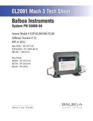
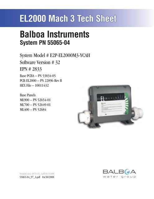
EL2000 Mach 3 Tech Sheet<strong>Balboa</strong> InstrumentsSystem PN <strong>55065</strong>-<strong>04</strong>System Model # <strong>E2P</strong>-<strong>EL2000M3</strong>-<strong>YCAH</strong>Software Version # 32EPN # 2833Base PCBA – PN 53834-05PCB EL2000 – PN 22896 Rev BHEX File – 10011432Base PanelsML900 – PN 52654-01ML700 – PN 52649-01ML400 – PN 52684Template used: 40573-v32_A.pdf <strong>04</strong>/15/2008<strong>55065</strong>-<strong>04</strong>_97_A.pdf <strong>04</strong>/30/2008Page 1<strong>55065</strong>-<strong>04</strong>_97_A
System Revision HistorySystem PN EPN Date Requested By Changes Made<strong>55065</strong>-<strong>04</strong> 2130 11.16.2006 B alboa Software update to v28<strong>55065</strong>-<strong>04</strong> n/a 07.20.2007 <strong>Balboa</strong> Software update to v30<strong>55065</strong>-<strong>04</strong> 2833 <strong>04</strong>.30.2008 <strong>Balboa</strong> Software update to v32Page 2<strong>55065</strong>-<strong>04</strong>_97_A
Basic System Features and FunctionsPower Requirements System OutputsSetup 1 (As Manufactured) AV Optional Devices Additional Options Connects to Main Panel terminal J70 or J71 or J72 Connects to Remote terminal J20 Connects to terminal J9 Connects to A.V. terminal J4W12J17J83AUX. FJ15Page 3J22G WJ3J36W2J80U4ADCMMAINPANELJ69J20 J71 J70J10 J39AUXPANELAUXPANELMAINPANELMAINPANELREMOTEJ13SENS. A J24 SENS. B VAC EXT. 2SP PUMP 3 EXT. RLYJ82J72J6J86<strong>55065</strong>-<strong>04</strong>_97_A
Persistent Memory and Powering UpAny time you change DIP Switches or Software Configuration Settings thataffect parameters the user can change (any filter settings, set temperaturedefault, Celsius vs Fahrenheit, 12-hour vs 24-hour time, reminderssuppression, etc), you must reset Persistent Memory for your DIP Switch orSoftware Configuration Settings changes to take effect. You should also resetPersistent Memory after loading a new file into a board (using the ESM,purchased seperately).To reset Persistent Memory: Power down. Set A12 ON (See illustration below). Power up. Wait until “ ” or “ ” is displayed on your panel.Note: If “ ” appears see section below. Set A12 OFF. (This can be done safely with power on if you use a nonconductivetool such as a pencil to push the switch back to the OFFposition. Otherwise, power down before setting A12 OFF) Power up again (if you powered down in the previous step). For all other power ups, leave A12 OFF.About Persistent Memory and Time of Day Retention:This system uses memory that doesn’t require a battery to store a varietyof settings. What we refer to as Persistent Memory stores all the UserPreferences, as well as all the filter settings, the set temperature, and theheat mode.Persistent Memory is not used for Time of Day. Time of Day needs to be“kept running” (not just stored) while the power is off, so a separate RealTime Clock feature (on all models except the EL1000) keeps track ofTime of Day while the unit is off. Time of Day Retention, and Time of DayRetention alone, is controlled by the J91 jumper. J91 must be set accordingto main system panel used.RTCEnabled(Not Jumpered)Switchbank AJ91RTCDisabled(Jumpered)J91Switchbank Bmessage on power up:If “ ” appears before (and instead of) “ ” or“ ”, you have not configured DIP Switches and/orSoftware Configuration Settings in a valid manner. This must be correctedbefore you can reset Persistent Memory.The switch numbers, jumpers, or configuration settings displayed after“ ” are ones with which the system has found a configuration problem.For example: “” would mean that the combination of how you’ve setA5 and how you’ve set B2 is not supported on this system. “ ” would mean that there is a problem with jumper J99 “ ” would mean that the combination of howyou’ve set pump 3 for 1-speed and blower for 1-speed is not supportedon this system. “ ” would mean that the combination of how you’veset DIP switches which have been assigned to pump 3 and blower is notsupported on this system.Power Up Display SequenceUpon power up, you should see the following on the display: Three numbers in a row, which are the SSID (the System SoftwareID). The third display of these numbers is the Software Version, whichshould match the version of your system. For example, if these threenumbers are , that is a Mach 3 EL8000 at version 26. If there is a Configuration Error, the message (see above) willappear at this point (and none of the messages below will display).Otherwise what comes next is: An indication of either the input voltage detected (EL1000/EL2000), orthe heater wattage range supported (EL8000/GL2000/GL8000). Heater wattage display: “ ” means the system supports a heaterfrom 1 kW to 3 kW. “ ” means the system supports a heaterfrom 3 kW to 6 kW. “ ” means the system supports a 3 kWheater only. (These ranges may be modified slightly in the case ofspecial heaters, which the next bullet covers.) Input voltage display: A system showing “ ” supports 3 kWto 6 kW heaters. A system showing “ ” supports the very sameheaters, although at 120V those heaters will function at only 1/4 oftheir 240V rated wattage. (The system shows only either “ ” or“ ” as a general indication of input voltage; it does not show theactual input voltage.) If your system is using a special type of heater, a display such as “ ”may appear next. If your system is using the generic <strong>Balboa</strong> heater, noheater type display will appear. “ ” or “ ” will appear to signal the start ofPriming Mode.At this point, the power up sequence is complete. Refer to the User Guidefor the ML Series panel on your system for information about how the spaoperates from this point on.Page 4<strong>55065</strong>-<strong>04</strong>_97_A
Wiring Configuration and DIP SettingsSetup 1 (As Manufactured) FUSE 30ACLASS GF6FUSE 30ACLASS GF7BLK ACJ66 J65 J64 J63TORQUERANGEFOR TB1:27-30 IN. LBS.K7W8GJ53WHT ACJ23 J19 J52 J43 J42 J50 J48NEUTRALWHITEHOTBLACKHOTREDA.V. W BTB1J57<strong>Balboa</strong>J54J25RJ55J26RED ACHTR2J79J4J56J7J11J37J74J8K81F2K6HTR15.5 kWK4K12312V LightFUSEJ46 3A 250VFUSE0.3A 250VBARCODEG RBWJ1 K11W1F4J892-Spd P1K13SpaLightW9WWJ14J12T1J91W712VACJ81K10J2J45SWITCHBANK ACirc.PumpG RBWRTC EnabledJ90K9J9J98G ROzoneBWW13SWITCHBANK BF5FUSE 10A 250VTSTCFG1-Spd P2G RBWJ5W12J17J83AUX. FJ15BALBOA INSTRUMENTS, INC. MADE IN U.S.A.EL2000 TC MACH III COPYRIGHT 2005P/N 22896 REV BG RBlowerBWJ3J97J36W2J82J80U4ADCMMAINPANELW20K2K3K12J69J39J20 J71 J70J10AUXPANELAUXPANELMAINPANELMAINPANELREMOTEJ13SENS. A SENS. B VAC EXT. 2SP PUMP 3 EXT. RLYJ22 J24J72J6J60J85W15J86WARNING: Main Power to system should be turned OFF BEFORE adjusting DIP switches.WARNING: Persistent Memory (A12) must be RESET to allow new DIP switch settings to take effect. (See Persistent Memory page)TSTCFGJ17J83AUX.FJ15A1, Test Mode OFFA2, Low High AmpA3, Filter by TimeA4, 12 Hr TimeA5, Degrees FA6, Short TimeoutsJ22 SENS. ASwitchbank AWhen the Logic Jumper is not installed on J83 (CFG),DIP Switch Settings are enabled.DIP Switches will then operate as shown below.A7, Cleanup Cycle OFFA8, 1Hr O 3 Supress OFFA9/A10,No Circ PumpA11, O3 w/ P1 Lowand P1 is 2-SpdA12, Memory RetainedSwitchbank BB1, Pump 2 2-Speed 1-SpeedB2, Pump 2 Disabled EnabledB3, Blower Disabled EnabledB4, No Fiber/WheelB5, Pump 3 DisabledB6, Panel Scrunching OFFPage 5SSID #1001143212 VLightRTCEnabled(Not Jumpered)J37J91123Wiring Color Key120 Volt Connections240 Volt ConnectionsBlack AC Jumpers12 Volt ConnectionsRelay Control WiresBoard Connector Key1 Typically Line voltage2 Typically Line voltage for 2-speed pumps3 Neutral (Common)4 GroundNote flat sides in connector<strong>55065</strong>-<strong>04</strong>_97_A
Panel ConfigurationsNote: RTC jumper (J91) on Main PCBA must be OFF (1 pin only)Time Warm Jets 1 Jets 2 Jets 3 OptionF1F2PLTLMode/Prog CoolInvert FiberLight BlowerTIME CAPABLEML900PN 52654-01 with Overlay PN 40026 Connects to Main Panel terminal J70, J71, or J72TimeWarmLightBlowerF1F2PLTLMode/ProgCoolJets 1Jets 2ML700PN 52649-01 with Overlay PN 11281 Connects to Main Panel terminal J70, J71, or J72NON-TIME CAPABLENote: Connects to Main Panel terminal J70, J71, or J72Note: RTC Jumper (J91) on Main PCBA must be ON (both pinsjumpered), unless a Time Capable panel is also used.ML400PN 52684 with Overlay PN 11345Jets Aux Temp LightHeatPage 8<strong>55065</strong>-<strong>04</strong>_97_A