55066-04, E2P-EL2001M3-YCAH - Balboa Direct
55066-04, E2P-EL2001M3-YCAH - Balboa Direct
55066-04, E2P-EL2001M3-YCAH - Balboa Direct
- No tags were found...

You also want an ePaper? Increase the reach of your titles
YUMPU automatically turns print PDFs into web optimized ePapers that Google loves.
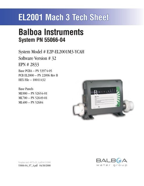
Persistent Memory and Powering UpAny time you change DIP Switches or Software Configuration Settings thataffect parameters the user can change (any filter settings, set temperaturedefault, Celsius vs Fahrenheit, 12-hour vs 24-hour time, reminderssuppression, etc), you must reset Persistent Memory for your DIP Switch orSoftware Configuration Settings changes to take effect. You should also resetPersistent Memory after loading a new file into a board (using the ESM,purchased seperately).To reset Persistent Memory: Power down. Set A12 ON (See illustration below). Power up. Wait until “ ” or “ ” is displayed on your panel.Note: If “ ” appears see section below. Set A12 OFF. (This can be done safely with power on if you use a nonconductivetool such as a pencil to push the switch back to the OFFposition. Otherwise, power down before setting A12 OFF) Power up again (if you powered down in the previous step). For all other power ups, leave A12 OFF.About Persistent Memory and Time of Day Retention:This system uses memory that doesn’t require a battery to store a varietyof settings. What we refer to as Persistent Memory stores all the UserPreferences, as well as all the filter settings, the set temperature, and theheat mode.Persistent Memory is not used for Time of Day. Time of Day needs to be“kept running” (not just stored) while the power is off, so a separate RealTime Clock feature (on all models except the EL1000) keeps track ofTime of Day while the unit is off. Time of Day Retention, and Time of DayRetention alone, is controlled by the J91 jumper. J91 must be set accordingto main system panel used.RTCEnabled(Not Jumpered)Switchbank AJ91RTCDisabled(Jumpered)J91Switchbank Bmessage on power up:If “ ” appears before (and instead of) “ ” or“ ”, you have not configured DIP Switches and/orSoftware Configuration Settings in a valid manner. This must be correctedbefore you can reset Persistent Memory.The switch numbers, jumpers, or configuration settings displayed after“ ” are ones with which the system has found a configuration problem.For example: “” would mean that the combination of how you’ve setA5 and how you’ve set B2 is not supported on this system. “ ” would mean that there is a problem with jumper J99 “ ” would mean that the combination of howyou’ve set pump 3 for 1-speed and blower for 1-speed is not supportedon this system. “ ” would mean that the combination of how you’veset DIP switches which have been assigned to pump 3 and blower is notsupported on this system.Power Up Display SequenceUpon power up, you should see the following on the display: Three numbers in a row, which are the SSID (the System SoftwareID). The third display of these numbers is the Software Version, whichshould match the version of your system. For example, if these threenumbers are , that is a Mach 3 EL8000 at version 26. If there is a Configuration Error, the message (see above) willappear at this point (and none of the messages below will display).Otherwise what comes next is: An indication of either the input voltage detected (EL1000/EL2000), orthe heater wattage range supported (EL8000/GL2000/GL8000). Heater wattage display: “ ” means the system supports a heaterfrom 1 kW to 3 kW. “ ” means the system supports a heaterfrom 3 kW to 6 kW. “ ” means the system supports a 3 kWheater only. (These ranges may be modified slightly in the case ofspecial heaters, which the next bullet covers.) Input voltage display: A system showing “ ” supports 3 kWto 6 kW heaters. A system showing “ ” supports the very sameheaters, although at 120V those heaters will function at only 1/4 oftheir 240V rated wattage. (The system shows only either “ ” or“ ” as a general indication of input voltage; it does not show theactual input voltage.) If your system is using a special type of heater, a display such as “ ”may appear next. If your system is using the generic <strong>Balboa</strong> heater, noheater type display will appear. “ ” or “ ” will appear to signal the start ofPriming Mode.At this point, the power up sequence is complete. Refer to the User Guidefor the ML Series panel on your system for information about how the spaoperates from this point on.Page 4<strong>55066</strong>-<strong>04</strong>_97_A
Panel ConfigurationsNote: RTC jumper (J91) on Main PCBA must be OFF (1 pin only)Time Warm Jets 1 Jets 2 Jets 3 OptionF1F2PLTLMode/Prog CoolInvert FiberLight BlowerTIME CAPABLEML900PN 52654-01 with Overlay PN 40026 Connects to Main Panel terminal J70, J71, or J72TimeWarmLightBlowerF1F2PLTLMode/ProgCoolJets 1Jets 2ML700PN 52649-01 with Overlay PN 11281 Connects to Main Panel terminal J70, J71, or J72NON-TIME CAPABLENote: Connects to Main Panel terminal J70, J71, or J72Note: RTC Jumper (J91) on Main PCBA must be ON (both pinsjumpered), unless a Time Capable panel is also used.ML400PN 52684 with Overlay PN 11345Jets Aux Temp LightHeatPage 8<strong>55066</strong>-<strong>04</strong>_97_A