Blade CX2 Manual - hapo - trade Modellbau
Blade CX2 Manual - hapo - trade Modellbau
Blade CX2 Manual - hapo - trade Modellbau

Create successful ePaper yourself
Turn your PDF publications into a flip-book with our unique Google optimized e-Paper software.
Channel 5 Knob Description and Function<br />
The transmitter included with your <strong>Blade</strong> <strong>CX2</strong> is equipped with an optional-use “Channel 5” knob (labeled as “CH 5”) on the top right<br />
panel.<br />
This knob allows you to control function of the transmitter’s 5th channel. This channel remains unused for flying the <strong>Blade</strong> <strong>CX2</strong>,<br />
however, it is available for use in controlling a variety of potential optional features including actuation of an additional servo or<br />
certain electronic components. It allows full proportional control of the 5th channel from approximately 0–100% travel.<br />
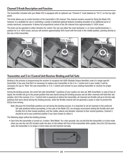
The knob can be operated in either direction for control. You can use either the most clockwise (+) or most counterclockwise (-)<br />
position for 0 or 100% travel, and you will achieve approximately 50% travel with the knob in the middle position, pointing directly to<br />
the rear of the transmitter.<br />
0% Travel<br />
50% Travel<br />
Transmitter and 3-in-1 Control Unit Receiver Binding and Fail-Safe<br />
23<br />
100% Travel<br />
Binding is the process of programming the receiver to recognize the GUID (Globally Unique Identifier) code of a single specific<br />
transmitter. If you ever find that it is necessary to replace your transmitter or the 3-in-1 control unit in your model, it will be<br />
necessary for you to “Bind” the new transmitter or 3-in-1 control unit receiver to your existing transmitter or receiver for proper<br />
operation.<br />
During the binding process, the smart fail-safe (SmartSafe ) positions of your system are also set. With SmartSafe, in case of loss of<br />
signal, the throttle will go to the preset position that was stored during the binding process and all other channels will hold their last<br />
position. And if the receiver (3-in-1 Control Unit) is powered on before the transmitter, all channels but throttle will go to the fail-safe<br />
positions that were stored during the binding process, while the throttle channel will not generate a pulse in order to prevent the<br />
ESC(s) from arming.<br />
Note: Because the SmartSafe positions are set during the binding process, it is important to set all channels to the preferred<br />
fail-safe positions before proceeding. In the case of the <strong>Blade</strong> <strong>CX2</strong>, we strongly recommend setting the throttle stick and<br />
throttle trim to their lowest positions, and the rudder, aileron and elevator channels to their neutral positions. Channel 5<br />
should be set to your preferred position if you have chosen to utilize it.<br />
The following steps outline the binding process:<br />
• Each time the transmitter is turned on, it enters “Bind Mode” for a few seconds. You can tell that the transmitter is in bind mode<br />
when you see the red LED located under the door on the bottom left front of the transmitter blink rapidly. Once the LED becomes<br />
solid, the transmitter is no longer in bind mode and will transmit normally.<br />
LED Location