KM-RIO Installation and Operation Manual - Kistler-Morse
KM-RIO Installation and Operation Manual - Kistler-Morse
KM-RIO Installation and Operation Manual - Kistler-Morse

Create successful ePaper yourself
Turn your PDF publications into a flip-book with our unique Google optimized e-Paper software.
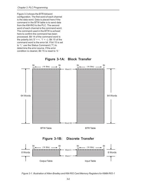
Chapter 3. PLC ProgrammingFigure 3-3 shows the BTR bit/wordconfiguration. The first word of each channelis the data word. Data is placed here if thecomm<strong>and</strong> in the BTW table is to send datafrom the <strong>KM</strong>-<strong>RIO</strong> to the PLC. The secondword of each channel is the comm<strong>and</strong> word.The comm<strong>and</strong> used in the BTW is echoedhere to confirm the comm<strong>and</strong> has beenprocessed. Bit 14 of the comm<strong>and</strong> word isthe polarity bit (‘0’ = +, ‘1’ = –). Bit 15 of thecomm<strong>and</strong> word is the error bit. If bit 15 is setto ‘1,’ use the Status Comm<strong>and</strong> (‘7’) todetermine the error source. If the errorcondition is cleared, Bit 15 is reset to ‘0.’Figure 3-1A: Block TransferBit15BitBit(16 Bits)015(16 Bits)Word 0Bit064 Words64 WordsWord 63BTW TableBTR TableFigure 3-1B:Discrete Transfer8 WordsBit15BitBit(16 Bits)015(16 Bits)Word 0Bit08 WordsWord 7Output TableInput TableFigure 3-1. Illustration of Allen-Bradley <strong>and</strong> <strong>KM</strong>-<strong>RIO</strong> Card Memory Registers for <strong>KM</strong>M-<strong>RIO</strong>-13-2