Basicflow double safety valve - series 9640 - Pentair Valves & Controls
Basicflow double safety valve - series 9640 - Pentair Valves & Controls
Basicflow double safety valve - series 9640 - Pentair Valves & Controls

You also want an ePaper? Increase the reach of your titles
YUMPU automatically turns print PDFs into web optimized ePapers that Google loves.
<strong>Basicflow</strong> <strong>double</strong> <strong>safety</strong> <strong>valve</strong> - <strong>series</strong> <strong>9640</strong>Installation & Maintenance InstructionsHOVAP1 Contents2 Introduction 22.1 Valve use 22.2 Application area 22.3 Incorrect use 23 Safety 24 Transport and storage 25 Installation instructions25.1 Mounting 25.2 Installation into pipework 25.3 Operating space 25.4 Mounting space 26 Operation 36.1 Operation with air 36.2 Indication of <strong>valve</strong> position 36.3 Control unit 37 Cleaning and maintenance 37.1 Cleaning 37.2 Lead-time 37.3 Safery measures during maintenance 37.4 Grease to be used 37.5 Disassembling the <strong>valve</strong> 37.6 Assembling the <strong>valve</strong> 47.7 Actuator 47.8 Failures 4Appendix A: Technical specification 5Version and ordering code 5Valve material 5Gasket material 5Air supply pressure 5Air consumption 5Appendix B: Cross-section 6Appendix C: Parts and spare parts 7Parts7Spare parts 7Ordering spare parts 7www.pentair.com/<strong>valve</strong>s<strong>Pentair</strong> reserves the right to change the contents without noticeHOVSB-0036-EN-1307
<strong>Basicflow</strong> <strong>double</strong> <strong>safety</strong> <strong>valve</strong> - <strong>series</strong> <strong>9640</strong>Installation & Maintenance Instructions2 Introduction2.1 Valve useThe Hovap <strong>Basicflow</strong> <strong>double</strong> <strong>safety</strong> <strong>valve</strong> <strong>series</strong> <strong>9640</strong> is a <strong>valve</strong> with a <strong>double</strong> seat.Product mixing because of a defective <strong>valve</strong> sealing must be prevented. Leaked product is drainedoutside the <strong>valve</strong>.2.2 Application areaThe <strong>valve</strong> has been designed for use in the food & beverage and pharmaceutical industries.2.3 Incorrect useThe <strong>valve</strong> is not suitable for use in gas systems.Liquids with hard solid parts cause increased wear to the gaskets.3 SafetyThe <strong>valve</strong> must be positioned such that cleaning liquid or leaked product from the <strong>valve</strong> cannotharm or damage individuals or the environment.There must be a free space of at least 150 mm above the <strong>valve</strong>. This prevents the jamming of partsof the body during opening/closing of the <strong>valve</strong>.Prevent that, during maintenance, liquids can pressurize the pipework in which the <strong>valve</strong> has beeninstalled.Prevent that fingers or hand get jammed between <strong>valve</strong> and seats during operation of adisconnected <strong>valve</strong>.During cleaning at elevated temperatures, the <strong>valve</strong> can become so hot that touching the surfacecauses burning.Do not open the actuator. Actuator is spring loaded!4 Transport and storageThe <strong>valve</strong> has been wrapped in plastic. This prevents dust and dirt entering the <strong>valve</strong> interior.Re-wrap the interior when the <strong>valve</strong> is unpacked for installation of the body into the pipework.5 Installation instructions5.1 MountingFor proper operation, the leak detector must be placed vertically, with the air cylinder pointing up.5.2 Installation into pipeworkThe <strong>valve</strong> can be welded in the pipework directly. Remove the <strong>valve</strong> internal parts, together withO-rings and gaskets, before welding.5.3 Operating spaceA free space is required above the <strong>valve</strong> of at least:Valve 1 1/2” : 25 mmValve 2” : 30 mmValve 2 1/2” : 35 mmValve 3” : 35 mmValve 4” : 40 mm5.4 Mounting spaceTo allow <strong>valve</strong> assembly and disassembly, a free space is required above the actuator of at least:Valve 1 1/2” : 90 mmValve 2” : 100 mmValve 2 1/2” : 110 mmValve 3” : 130 mmValve 4” : 155 mm<strong>Pentair</strong> reserves the right to change the contents without notice page 2
<strong>Basicflow</strong> <strong>double</strong> <strong>safety</strong> <strong>valve</strong> - <strong>series</strong> <strong>9640</strong>Installation & Maintenance Instructions6 Operation6.1 Operation with airThe <strong>valve</strong> is provided with two air connections with 1/8” BSP female thread.P I: Close <strong>valve</strong> (for spring-to-open and <strong>double</strong>-acting <strong>valve</strong>s).P II: Open <strong>valve</strong> (for spring-to-close <strong>valve</strong>s).P III: Close CIP <strong>valve</strong>s with <strong>valve</strong> in open position.Air connections that are not in use must be fitted with bleeding nipples.6.2 Indication of <strong>valve</strong> position.The <strong>valve</strong> can be provided with a bracket for proximity switches. Following positions are possible:Open indication Closed indication Open/closed indication6.3 Control unitThe <strong>valve</strong> can also be provided with a control unit. Most commercially available units can be fitted.7 Cleaning and maintenance7.1 CleaningThe <strong>valve</strong> is suitable for CIP cleaning. If the <strong>valve</strong> is in closed position, the cavity between both<strong>valve</strong> sealing rings can be cleaned by flushing one of the the two CIP <strong>valve</strong>s. Both CIP <strong>valve</strong>s mustbe in the open position.The <strong>valve</strong> material is resistant to detergents that are commonly used in the food industry, such as alye (NaOH) or acid (HNO 3 ) solution of about 1% at a temperature of about 80°C. After cleaning, thesystem must be rinsed with clean water to prevent corrosion.7.2 Lead-timeSealing and wearing parts of the <strong>valve</strong> must be checked once a year. For special applications (suchas highly viscous or crystallizing liquids) the lead-time must be adjusted in consultation with themanufacturer.7.3 Safety measures during maintenanceBefore starting disassembly of the <strong>valve</strong>, the piping must be fully drained. When the <strong>valve</strong> isdisassembled or removed from the line, pressurizing of the line, e.g. by (remote) operation of apump or a <strong>valve</strong>, must be prevented.Before assembly or disassembly of spring-return <strong>valve</strong>s, compressed air must be used to move<strong>valve</strong> in open position. This prevents that the closing force of the spring opens the <strong>valve</strong>.7.4 Grease to be usedWetted O-rings must be greased with grease that has been approved for use in the food industry.We recommend Molykote 111.7.5 Disassembling the <strong>valve</strong>See Appendix BA - Remove, if present, the indicators.B - For spring-to-close <strong>valve</strong>s, supply pressurized air to P II.C - Loosen clamp 12.D - Pull actuator 8, together with interior, from <strong>valve</strong> body 1.E - For spring-to-close <strong>valve</strong>s, remove air pressure from P II.F - Loosen insert 78 (for 1 1/2” <strong>valve</strong>s) or nut 79 (other sizes).G - Loosen cover of CIP <strong>valve</strong> 2.H - Check all O-rings.<strong>Pentair</strong> reserves the right to change the contents without notice page 3
<strong>Basicflow</strong> <strong>double</strong> <strong>safety</strong> <strong>valve</strong> - <strong>series</strong> <strong>9640</strong>Installation & Maintenance Instructions - Appendix A – Technical specificationVersion and ordering codeThe following versions are available:VersionOrdering code9641 9642Valve materialAll metal parts that come into contact with the liquid are made of stainless steel according toW.Nr. 1.4404. The metal parts that do not come into contact with the liquid are made of stainlesssteel W.Nr. 1.4301 or plastic. The actuator bearings are made of self-lubricating bronze.Gasket materialThe O-rings that come into contact with the liquid are made of EPDM. Alternatives are available.Air supply pressureThe air supply pressure must be between 6 and 10 bar. We recommend dry air of 6 bar.Air consumptionThe air consumption in nl. per stroke is given in the table below. The consumption is calculated at6 bar air pressure.Dimension Spring-to-close Double acting1 1/2” 1.3 4.32” 1.3 4.42 1/2” 2.8 12.33” 3.3 13.14” 5.4 26.5<strong>Pentair</strong> reserves the right to change the contents without notice page 5
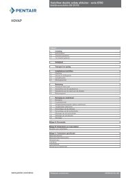
<strong>Basicflow</strong> <strong>double</strong> <strong>safety</strong> <strong>valve</strong> - <strong>series</strong> <strong>9640</strong>Installation & Maintenance Instructions - Appendix B - Cross-section2618826199211262217620272387978 28 2977<strong>Pentair</strong> reserves the right to change the contents without notice page 6
<strong>Basicflow</strong> <strong>double</strong> <strong>safety</strong> <strong>valve</strong> - <strong>series</strong> <strong>9640</strong>Installation & Maintenance Instructions - Appendix C - parts and spare partsPartsRef. no. Qty. MaterialDescription1 1 W. Nr. 1.4404 Valve body2 1 W. Nr. 1.4404 CIP <strong>valve</strong>6 1 W. Nr. 1.4404 Stem <strong>valve</strong> plate8 1 W. Nr. 1.4301 Actuator9 1 W. Nr. 1.4301 Connecting piece12 1 W. Nr. 1.4301 Clamp18 1 W. Nr. 1.4301 Top cover19 1 W. Nr. 1.4301 O-ring retainer20+29 1 EPDM-FDA O-ring set21 2 EPDM-FDA O-ring22 1 EPDM-FDA O-ring26 2 FPM O-ring27 1 EPDM-FDA O-ring28 1 EPDM-FDA O-ring38 1 EPDM-FDA O-ring76 1 W. Nr. 1.4404 Stem <strong>valve</strong> and shaft77 1 W. Nr. 1.4404 Valve part78 1 W. Nr. 1.4404 Insert79 1 W. Nr. 1.4404 NutSpare partsRef. no. Descr. 1 1/2” 2” 2 1/2” 3” 4”DN40 DN50 DN65 DN80 DN1002 CIP <strong>valve</strong>20+29 O-ring set 37.47 x 5.33 50.17 x 5.33 62.87 x 5.33 75.57 x 5.33 97.79 x 5.3326.34 x 5.33 37.47 x 5.33 50.17 x 5.33 66.04 x 5.33 88.27 x 5.3321 O-ring 18 x 3 18 x 3 18 x 3 22 x 3 22 x 322 O-ring 56.52 x 5.33 66.04 x 5.33 75.57 x 5.33 94.62 x 5.33 113.67 x 5.3326 O-ring 18 x 3 18 x 3 18 x 3 22 x 3 22 x 327 O-ring 28 x 2 39 x 2 50 x 2 60 x 2 80 x 228 O-ring 12 x 2 24 x 2 30 x 2 40 x 2 60 x 238 O-ring - 12 x 2 12 x 2 18 x 2 18 x 2NoteO-rings 20 and 29 both should be replaced atthe same time and are delivered as one set.Ordering spare partsWhen ordering spare parts, please include thefollowing information:• The <strong>valve</strong> number.• The <strong>valve</strong> ordering code. See Appendix A.• The <strong>valve</strong> size.• The <strong>valve</strong> part position number.• The quality of O-rings.<strong>Pentair</strong> reserves the right to change the contents without notice page 7