DTC B1800/51 Short in Driver Side Squib Circuit ... - mineznaem.ru
DTC B1800/51 Short in Driver Side Squib Circuit ... - mineznaem.ru
DTC B1800/51 Short in Driver Side Squib Circuit ... - mineznaem.ru
- No tags were found...

Create successful ePaper yourself
Turn your PDF publications into a flip-book with our unique Google optimized e-Paper software.
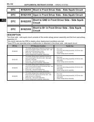
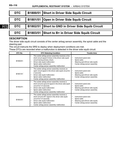
RS–118SUPPLEMENTAL RESTRAINT SYSTEM – AIRBAG SYSTEM<strong>DTC</strong> <strong>B1800</strong>/<strong>51</strong> <strong>Short</strong> <strong>in</strong> <strong>Driver</strong> <strong>Side</strong> <strong>Squib</strong> <strong>Circuit</strong><strong>DTC</strong> B1801/<strong>51</strong> Open <strong>in</strong> <strong>Driver</strong> <strong>Side</strong> <strong>Squib</strong> <strong>Circuit</strong>RS<strong>DTC</strong> B1802/<strong>51</strong> <strong>Short</strong> to GND <strong>in</strong> <strong>Driver</strong> <strong>Side</strong> <strong>Squib</strong> <strong>Circuit</strong><strong>DTC</strong> B1803/<strong>51</strong> <strong>Short</strong> to B+ <strong>in</strong> <strong>Driver</strong> <strong>Side</strong> <strong>Squib</strong> <strong>Circuit</strong>DESCRIPTIONThe driver side squib circuit consists of the center airbag sensor assembly, the spiral cable and thesteer<strong>in</strong>g pad.The circuit <strong>in</strong>st<strong>ru</strong>cts the SRS to deploy when deployment conditions are met.These <strong>DTC</strong>s are recorded when a malfunction is detected <strong>in</strong> the driver side squib circuit.<strong>DTC</strong> No. <strong>DTC</strong> Detect<strong>in</strong>g Condition Trouble Area<strong>B1800</strong>/<strong>51</strong>B1801/<strong>51</strong>B1802/<strong>51</strong>B1803/<strong>51</strong>• The center airbag sensor assembly receives a l<strong>in</strong>eshort circuit signal 5 times <strong>in</strong> the driver side squibcircuit dur<strong>in</strong>g primary check.• <strong>Driver</strong> side squib malfunction• Spiral cable malfunction• Center airbag sensor assembly malfunction• The center airbag sensor assembly receives anopen circuit signal <strong>in</strong> the driver side squib circuit for2 seconds.• <strong>Driver</strong> side squib malfunction• Spiral cable malfunction• Center airbag sensor assembly malfunction• The center airbag sensor assembly receives ashort circuit to ground signal <strong>in</strong> the driver side squibcircuit for 0.5 seconds.• <strong>Driver</strong> side squib malfunction• Spiral cable malfunction• Center airbag sensor assembly malfunction• The center airbag sensor assembly receives ashort circuit to B+ signal <strong>in</strong> the driver side squibcircuit for 0.5 seconds.• <strong>Driver</strong> side squib malfunction• Spiral cable malfunction• Center airbag sensor assembly malfunction• Inst<strong>ru</strong>ment panel wire• Spiral cable• Steer<strong>in</strong>g pad (<strong>Driver</strong> side squib)• Center airbag sensor assembly• Inst<strong>ru</strong>ment panel wire• Spiral cable• Steer<strong>in</strong>g pad (<strong>Driver</strong> side squib)• Center airbag sensor assembly• Inst<strong>ru</strong>ment panel wire• Spiral cable• Steer<strong>in</strong>g pad (<strong>Driver</strong> side squib)• Center airbag sensor assembly• Inst<strong>ru</strong>ment panel wire• Spiral cable• Steer<strong>in</strong>g pad (<strong>Driver</strong> side squib)• Center airbag sensor assembly
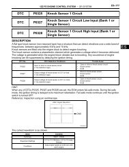
RS–120SUPPLEMENTAL RESTRAINT SYSTEM – AIRBAG SYSTEM1 CHECK STEERING PAD (DRIVER SIDE SQUIB)RSF ESpiral Cable<strong>Driver</strong> <strong>Side</strong> <strong>Squib</strong>Connector EDLC3CG TCCDCCenter AirbagSensor AssemblySSTColor: Orange<strong>DTC</strong> <strong>51</strong>C114804E01(a) Turn the ignition switch to the LOCK position.(b) Disconnect the negative (-) term<strong>in</strong>al cable from thebattery, and wait for at least 90 seconds.(c) Disconnect the connectors from the steer<strong>in</strong>g pad.(d) Connect the white wire side of SST (resistance 2.1 Ω) toconnector "E" (orange connector).CAUTION:Never connect a tester to the steer<strong>in</strong>g pad (driverside squib) for measurement, as this may lead to aserious <strong>in</strong>jury due to airbag deployment.NOTICE:• Do not forcibly <strong>in</strong>sert the SST <strong>in</strong>to the term<strong>in</strong>als ofthe connector when connect<strong>in</strong>g.• Insert straight the SST <strong>in</strong>to the term<strong>in</strong>als of theconnector.SST 09843-18060(e) Connect the negative (-) term<strong>in</strong>al cable to the battery,and wait for at least 2 seconds.(f) Turn the ignition switch to the ON position, and wait for atleast 60 seconds.(g) Clear the <strong>DTC</strong>s stored <strong>in</strong> the memory (See page RS-34).(h) Turn the ignition switch to the LOCK position.(i) Turn the ignition switch to the ON position, and wait for atleast 60 seconds.(j) Check the <strong>DTC</strong>s (See page RS-34).OK:<strong>DTC</strong> <strong>B1800</strong>, B1801, B1802, B1803 or <strong>51</strong> is notoutput.HINT:Codes other than <strong>DTC</strong> <strong>B1800</strong>, B1801, B1802, B1803and <strong>51</strong> may be output at this time, but they are notrelated to this check.NGGo to step 2OKREPLACE STEERING PAD2 CHECK CONNECTOR(a)(b)(c)(d)Turn the ignition switch to the LOCK position.Disconnect the negative (-) term<strong>in</strong>al cable from thebattery, and wait for at least 90 seconds.Disconnect the SST from connector "E".Check that the spiral cable connectors (on the steer<strong>in</strong>gpad side) are not damaged.
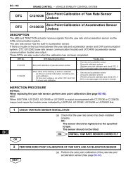
SUPPLEMENTAL RESTRAINT SYSTEM – AIRBAG SYSTEMRS–121OK:The lock button is not disengaged, or the claw ofthe lock is not deformed or damaged.NGREPLACE SPIRAL CABLEOKRS3 CHECK DRIVER SIDE SQUIB CIRCUIT<strong>Driver</strong> <strong>Side</strong> <strong>Squib</strong>F E DC BSpiral CableConnector EACenter AirbagSensor Assembly(a)(b)Disconnect the connectors from the center airbag sensorassembly.Check for a short to B+ <strong>in</strong> the circuit.(1) Connect the negative (-) term<strong>in</strong>al cable to thebattery, and wait for at least 2 seconds.(2) Turn the ignition switch to the ON position.(3) Measure the voltage accord<strong>in</strong>g to the value(s) <strong>in</strong> thetable below.Standard voltageTester connection Condition Specified conditionD+ - Body ground Ignition switch ON Below 1 VD- - Body ground Ignition switch ON Below 1 VCD-D+Color: OrangeC114805E01(c)Check for an open <strong>in</strong> the circuit.(1) Turn the ignition switch to the LOCK position.(2) Disconnect the negative (-) term<strong>in</strong>al cable from thebattery, and wait for at least 90 seconds.(3) Measure the resistance accord<strong>in</strong>g to the value(s) <strong>in</strong>the table below.Standard resistanceTester connection Condition Specified conditionD+ - D- Always Below 1 Ω(d)Check for a short to ground <strong>in</strong> the circuit.(1) Measure the resistance accord<strong>in</strong>g to the value(s) <strong>in</strong>the table below.Standard resistanceTester connection Condition Specified conditionD+ - Body ground Always 1 MΩ or higherD- - Body ground Always 1 MΩ or higher(e)Check for a short <strong>in</strong> the circuit.(1) Release the activation prevention mechanism built<strong>in</strong>to connector "B" (See page RS-26).(2) Measure the resistance accord<strong>in</strong>g to the value(s) <strong>in</strong>the table below.Standard resistanceTester connection Condition Specified conditionD+ - D- Always 1 MΩ or higherNGGo to step 5OK
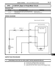
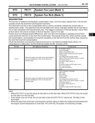
RS–122SUPPLEMENTAL RESTRAINT SYSTEM – AIRBAG SYSTEM4 CHECK CENTER AIRBAG SENSOR ASSEMBLYRSFESpiral Cable<strong>Driver</strong> <strong>Side</strong> <strong>Squib</strong>DLC3CG TCCDCCenter AirbagSensor Assembly<strong>DTC</strong> <strong>51</strong>C114806E01(a)(b)(c)(d)(e)(f)(g)Connect the connectors to the steer<strong>in</strong>g pad and thecenter airbag sensor assembly.Connect the negative (-) term<strong>in</strong>al cable to the battery,and wait for at least 2 seconds.Turn the ignition switch to the ON position, and wait for atleast 60 seconds.Clear the <strong>DTC</strong>s stored <strong>in</strong> the memory (See page RS-34).Turn the ignition switch to the LOCK position.Turn the ignition switch to the ON position, and wait for atleast 60 seconds.Check the <strong>DTC</strong>s (See page RS-34).OK:<strong>DTC</strong> <strong>B1800</strong>, B1801, B1802, B1803 or <strong>51</strong> is notoutput.HINT:Codes other than <strong>DTC</strong> <strong>B1800</strong>, B1801, B1802, B1803and <strong>51</strong> may be output at this time, but they are notrelated to this check.NGREPLACE CENTER AIRBAG SENSORASSEMBLYOKUSE SIMULATION METHOD TO CHECK5 CHECK INSTRUMENT PANEL WIREInst<strong>ru</strong>ment Panel WireF E D C BSpiral Cable<strong>Driver</strong> <strong>Side</strong> <strong>Squib</strong>ACenter AirbagSensor Assembly(a)(b)(c)Restore the released activation prevention mechanismof connector "B" to the orig<strong>in</strong>al condition.Disconnect the <strong>in</strong>st<strong>ru</strong>ment panel wire connector from thespiral cable.Check for a short to B+ <strong>in</strong> the circuit.(1) Connect the negative (-) term<strong>in</strong>al cable to thebattery, and wait for at least 2 seconds.(2) Turn the ignition switch to the ON position.(3) Measure the voltage accord<strong>in</strong>g to the value(s) <strong>in</strong> thetable below.Standard voltageTester connection Condition Specified conditionConnector “C”A16-1 (D+) - Body ground Ignition switch ON Below 1 VCA16D-D+C114807E14A16-2 (D-) - Body ground Ignition switch ON Below 1 V(d)Check for an open <strong>in</strong> the circuit.(1) Turn the ignition switch to the LOCK position.(2) Disconnect the negative (-) term<strong>in</strong>al cable from thebattery, and wait for at least 90 seconds.(3) Measure the resistance accord<strong>in</strong>g to the value(s) <strong>in</strong>the table below.
SUPPLEMENTAL RESTRAINT SYSTEM – AIRBAG SYSTEMRS–123(e)Standard resistanceTester connection Condition Specified conditionA16-1 (D+) - A16-2 (D-) Always Below 1 ΩCheck for a short to ground <strong>in</strong> the circuit.(1) Measure the resistance accord<strong>in</strong>g to the value(s) <strong>in</strong>the table below.Standard resistanceRSTester connection Condition Specified conditionA16-1 (D+) - Body ground Always 1 MΩ or higherA16-2 (D-) - Body ground Always 1 MΩ or higher(f)Check for a short <strong>in</strong> the circuit.(1) Release the activation prevention mechanism built<strong>in</strong>to connector "B" (See page RS-26).(2) Measure the resistance accord<strong>in</strong>g to the value(s) <strong>in</strong>the table below.Standard resistanceTester connection Condition Specified conditionA16-1 (D+) - A16-2 (D-) Always 1 MΩ or higherNGREPAIR OR REPLACE INSTRUMENT PANELWIREOK6 CHECK SPIRAL CABLEInst<strong>ru</strong>ment Panel WireF E DC BSpiral Cable<strong>Driver</strong> <strong>Side</strong> <strong>Squib</strong>ACenter AirbagSensor Assembly(a)Check for a short to B+ <strong>in</strong> the circuit.(1) Connect the negative (-) term<strong>in</strong>al cable to thebattery, and wait for at least 2 seconds.(2) Turn the ignition switch to the ON position.(3) Measure the voltage accord<strong>in</strong>g to the value(s) <strong>in</strong> thetable below.Standard voltageTester connection Condition Specified conditionD+ - Body ground Ignition switch ON Below 1 VD- - Body ground Ignition switch ON Below 1 VConnector ED-D+Color: Orange(b)Check for an open <strong>in</strong> the circuit.(1) Turn the ignition switch to the LOCK position.(2) Disconnect the negative (-) term<strong>in</strong>al cable from thebattery, and wait for at least 90 seconds.(3) Measure the resistance accord<strong>in</strong>g to the value(s) <strong>in</strong>the table below.Standard resistanceCC114808E01(c)Tester connection Condition Specified conditionD+ - D- Always Below 1 ΩCheck for a short to ground <strong>in</strong> the circuit.(1) Measure the resistance accord<strong>in</strong>g to the value(s) <strong>in</strong>the table below.
RS–124SUPPLEMENTAL RESTRAINT SYSTEM – AIRBAG SYSTEMRS(d)Standard resistanceTester connection Condition Specified conditionD+ - Body ground Always 1 MΩ or higherD- - Body ground Always 1 MΩ or higherCheck for a short <strong>in</strong> the circuit.(1) Release the activation prevention mechanism built<strong>in</strong>to connector "D" (See page RS-26).(2) Measure the resistance accord<strong>in</strong>g to the value(s) <strong>in</strong>the table below.Standard resistanceTester connection Condition Specified conditionD+ - D- Always 1 MΩ or higherNGREPLACE SPIRAL CABLEOKUSE SIMULATION METHOD TO CHECK