DTC C0278/11 Open in ABS Solenoid Relay Circuit ... - mineznaem.ru
DTC C0278/11 Open in ABS Solenoid Relay Circuit ... - mineznaem.ru
DTC C0278/11 Open in ABS Solenoid Relay Circuit ... - mineznaem.ru

Create successful ePaper yourself
Turn your PDF publications into a flip-book with our unique Google optimized e-Paper software.
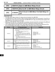
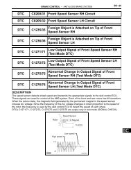
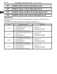
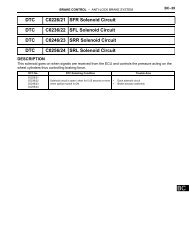
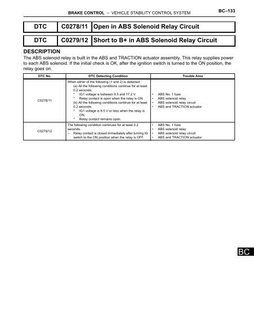
BRAKE CONTROL – VEHICLE STABILITY CONTROL SYSTEMBC–133<strong>DTC</strong> <strong>C0278</strong>/<strong>11</strong> <strong>Open</strong> <strong>in</strong> <strong>ABS</strong> <strong>Solenoid</strong> <strong>Relay</strong> <strong>Circuit</strong><strong>DTC</strong> C0279/12 Short to B+ <strong>in</strong> <strong>ABS</strong> <strong>Solenoid</strong> <strong>Relay</strong> <strong>Circuit</strong>DESCRIPTIONThe <strong>ABS</strong> solenoid relay is built <strong>in</strong> the <strong>ABS</strong> and TRACTION actuator assembly. This relay supplies powerto each <strong>ABS</strong> solenoid. If the <strong>in</strong>itial check is OK, after the ignition switch is turned to the ON position, therelay goes on.<strong>DTC</strong> No. <strong>DTC</strong> Detect<strong>in</strong>g Condition Trouble Area<strong>C0278</strong>/<strong>11</strong>C0279/12When either of the follow<strong>in</strong>g (1 and 2) is detected:(a) All the follow<strong>in</strong>g conditions cont<strong>in</strong>ue for at least0.2 seconds.* IG1 voltage is between 9.5 and 17.2 V.* <strong>Relay</strong> contact is open when the relay is ON.(b) All the follow<strong>in</strong>g conditions cont<strong>in</strong>ue for at least0.2 seconds.* IG1 voltage is 9.5 V or less when the relay isON.* <strong>Relay</strong> contact rema<strong>in</strong>s open.The follow<strong>in</strong>g condition cont<strong>in</strong>ues for at least 0.2seconds.– <strong>Relay</strong> contact is closed immediately after turn<strong>in</strong>g IGswitch to the ON position when the relay is OFF.• <strong>ABS</strong> No. 1 fuse• <strong>ABS</strong> solenoid relay• <strong>ABS</strong> solenoid relay circuit• <strong>ABS</strong> and TRACTION actuator• <strong>ABS</strong> No. 1 fuse• <strong>ABS</strong> solenoid relay• <strong>ABS</strong> solenoid relay circuit• <strong>ABS</strong> and TRACTION actuatorBC
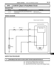
BC–134BRAKE CONTROL – VEHICLE STABILITY CONTROL SYSTEMWIRING DIAGRAM<strong>ABS</strong> and TRACTION Actuator AssemblySkid Control ECUALT <strong>ABS</strong> No. <strong>11</strong> 2 1 2 31 +BS<strong>Solenoid</strong> <strong>Relay</strong>SFRHSFLHSRRHSRLHSFRRSFLR32GND1SRRRSRLRBCFL MAINBattery1GND2C132773E02
BRAKE CONTROL – VEHICLE STABILITY CONTROL SYSTEMBC–135INSPECTION PROCEDURENOTICE:When replac<strong>in</strong>g the <strong>ABS</strong> and TRACTION actuator assembly, perform zero po<strong>in</strong>t calibration (Seepage BC-80).1 INSPECT <strong>ABS</strong> NO. 1 FUSEEng<strong>in</strong>e Room R/B(a)(b)Remove the <strong>ABS</strong> No. 1 fuse from the eng<strong>in</strong>e room R/B.Measure the resistance accord<strong>in</strong>g to the value(s) <strong>in</strong> thetable below.Standard resistanceTester Connection<strong>ABS</strong> No. 1 fuseSpecified ConditionBelow 1 Ω (Cont<strong>in</strong>uity)NGREPLACE <strong>ABS</strong> NO. 1 FUSE<strong>ABS</strong> No. 1FuseF049364E04OK2 INSPECT SKID CONTROL ECU (+BS TERMINAL)Skid Control ECU (harness side connector)(a)(b)Disconnect the skid control ECU connector.Measure the voltage accord<strong>in</strong>g to the value(s) <strong>in</strong> thetable below.Standard voltageTester Connection Condition Specified Condition+BSS1F049362E68S1-31 (+BS) - BodygroundNGAlways10 to 14 VREPAIR OR REPLACE HARNESS ORCONNECTOR (+BS CIRCUIT)BCOK
BC–136BRAKE CONTROL – VEHICLE STABILITY CONTROL SYSTEM3 INSPECT SKID CONTROL ECU (GND TERMINAL)Skid Control ECU (harness side connector)(a)(b)Disconnect the skid control ECU connector.Measure the resistance accord<strong>in</strong>g to the value(s) <strong>in</strong> thetable below.Standard resistanceTester ConnectionSpecified ConditionS1-32 (GND1) - Body ground Below 1 ΩGND1S1F049362E69NGREPAIR OR REPLACE HARNESS ORCONNECTOR (GND CIRCUIT)OK4 RECONFIRM <strong>DTC</strong>HINT:These codes are detected when a problem is determ<strong>in</strong>ed <strong>in</strong>the <strong>ABS</strong> and TRACTION actuator assembly.The <strong>ABS</strong> solenoid relay is <strong>in</strong> the <strong>ABS</strong> and TRACTIONactuator assembly.Therefore, solenoid relay circuit <strong>in</strong>spection relay unit<strong>in</strong>spection cannot be performed. Be sure to check if the <strong>DTC</strong>code is output before replac<strong>in</strong>g the <strong>ABS</strong> and TRACTIONactuator assembly.(a) Clear the <strong>DTC</strong>s (See page BC-96).(b) Turn the ignition switch to the ON position.(c) Are the same <strong>DTC</strong>s recorded?NOENDYESREPLACE <strong>ABS</strong> AND TRACTION ACTUATOR ASSEMBLYBC