

Probabilistic Method for Predicting Ship Collision Damage
Probabilistic Method for Predicting Ship Collision Damage
Probabilistic Method for Predicting Ship Collision Damage

You also want an ePaper? Increase the reach of your titles
YUMPU automatically turns print PDFs into web optimized ePapers that Google loves.
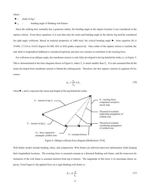
where:e i - strain in leg iq bi - bending angle of flanking web framesSince the striking bow normally has a generous radius, the bending angle at the impact location is not considered in therupture criteria. From these equations, it is seen that only the strain and bending angle in the shorter leg need be considered<strong>for</strong> right angle collisions. Based on material properties of ABS steel, the critical bending angle q c from equation (8) is19.896, 17.318 or 16.812 degrees <strong>for</strong> MS, H32 or H36 grades respectively. Once either of the rupture criteria is reached, theside shell or longitudinal bulkhead is considered ruptured, and does not continue to contribute to the reacting <strong>for</strong>ce.For collisions at an oblique angle, the membrane tension is only fully developed in the leg behind the strike, L 2 in Figure 5.This is demonstrated in the <strong>for</strong>ce diagram shown in Figure 6, where T 1 is much smaller than T 2 . It is also assumed that all thestrain developed from membrane tension is behind the striking point. There<strong>for</strong>e, the first rupture criterion in equation (9) becomes:where e b and L b represent the strain and length of the leg behind the strike.etεb= ≤ ε(10)rLbT 2 – tension in leg L 2N - reacting <strong>for</strong>cecomponent normal tostruck shipTheoretical resultantneglecting propagation ofyielded zoneT 1 – tension in leg L 1Theoretical resultantconsidering propagationof yielded zoneFR - <strong>for</strong>ce required topropagate yielded zoneFf - nominal frictionFigure 6. Oblique collision <strong>for</strong>ce diagram [McDermott 1974]Web failure modes include bending, shear, and compression. Web frames are allowed transverse de<strong>for</strong>mation while keepingtheir longitudinal locations. The resisting <strong>for</strong>ce is assumed constant at a distorted flanking web frame, and the transverse de<strong>for</strong>mationof the web frame is assumed uni<strong>for</strong>m from top to bottom. The magnitude of this <strong>for</strong>ce is its maximum elastic capacity.From Figure 6, the applied <strong>for</strong>ce on a rigid flanking web frame is:wP i = T(11)iLi9


