Manual Backflow Preventer Test Kit TK 9A - Watts waterbeveiliging
Manual Backflow Preventer Test Kit TK 9A - Watts waterbeveiliging
Manual Backflow Preventer Test Kit TK 9A - Watts waterbeveiliging

You also want an ePaper? Increase the reach of your titles
YUMPU automatically turns print PDFs into web optimized ePapers that Google loves.
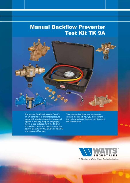
<strong>Manual</strong> <strong>Backflow</strong> <strong>Preventer</strong> <strong>Test</strong> <strong>Kit</strong> <strong>TK</strong> <strong>9A</strong>2differentialpressure gaugehigh pressure hose(yellow)shutoff valvesA00.250.5BAR0.751BClowpressurehose(red)(blue)Description of the test kitA, B, C – valves1,2,3 – test valves4,5 – shutoff valvesThe non-return protective device BA BM for thedimensions DN 15 up to and incl. DN 50 are shownin the instructions in this manual. The test kit canalso be used for other non-return protective devices.In that case the position of the test valves differs(see figure 2).Connecting test kitshutoff valve4test valves12 3shutoff valve51. Close valves A, B and C of the test kit.2. Connect the high-pressure hose (yellow) totest valve 1.3. Connect the low-pressure hose (red) totest valve 2.4. Close valve 5 (this valve must be absolutelyleak tightened).5. Open the test valves 1 and 2 and valve 4.6. Open valve C.7. Open valve A to de-aerate and then close it.8. Open valve B to de-aerate and then close it.9. Close valve C.10. Connect the blue hose to test valve 3.11. Open test valve 3.openclosedFigure 1: BA BM DN15 up to DN501 2 32 311BA 909 DN65 up to DN250BA 009 DN15 up to DN501 2 3 123123BA BS DN6 up to DN10BA 909 DN20 up to DN50BA 009 DN65 and DN80Figure 2: Position of the test valves
<strong>Manual</strong> <strong>Backflow</strong> <strong>Preventer</strong> <strong>Test</strong> <strong>Kit</strong> <strong>TK</strong> <strong>9A</strong><strong>Test</strong> no. 1 - <strong>Test</strong>ing valve 5Aim: testing whether valve 5 is leak tightened.Valve 5 must be fully closed in order to performtests no. 1, 3 and 4 accurately.1. Connect the test kit (see page 2:“Connecting test kit”).2. Check whether:• valves A, B and C are closed.• test valves 1, 2 and 3 are open.• Shutoff valve 4 is open.• Shutoff valve 5 is closed.3. Close test valve 1.4. Open valves A and C.Close Shutoff valve 5 well if the measureddifference in pressure remains constant. If thedifference in pressure drops back, this indicates aleakage/contamination of Shutoff valve 5. In thiscase replace Shutoff valve 5.<strong>Test</strong> no. 2 - <strong>Test</strong>ing of 2 nd non-return valveAim: testing whether the 2 nd check valve is closed(at the outflow side). This check valve must fullyleak tightened under all conditions.1. Connect the test kit (see page 2:“Connecting test kit”).2. Check whether:• valves A, B and C are closed.• test valves 1, 2 and 3 are open.• Shutoff valve 4 is open.• Shutoff valve 5 is closed.3. Open valves A and C.The measures difference in pressure will becomesmaller. If the difference in pressure continues todrop back until the relief valve opens, this indicatesa leakage/contamination of the 2 nd check valve. Inthis case replace or repair the 2 nd check valve.<strong>Test</strong> no. 4 - <strong>Test</strong>ing of the relief valveAim: testing the relief valve in the pressure-reducedzone. This relief valve must open when the pressurein the intermediate chamber (between the first andsecond non-recurrent valve) is still at least 14 kPalower than the pressure at the inflow side.1. Connect the test kit (see page 2:“Connecting test kit”).2. Check whether:• valves A, B and C are closed.• test valves 1, 2 and 3 are open.• Shutoff valve 4 is open.• Shutoff valve 5 is closed.3. Close test valve 3.4. Open valve A.5. Very slowly open valve B, until the measureddifference in pressure starts to drop back.N.B.: It is important that the value on thedifferential pressure gauge gradually dropsback.6. Leave valve B in this position and read thevalue on the differential pressure gauge atthe moment that water begins to drip from theoutlet passage.The value read at that moment is the openingdifferential pressure of the relief valve. Replaceor repair the relief valve if the read value is lessthan 14 kPa.Dismounting the test kit.1. Close the test valves 1, 2 and 3.2. Disconnect the 3 hoses (yellow, red and blue)3. Open Shutoff valve 5.3<strong>Test</strong> no. 3 - <strong>Test</strong>ing of 1 st non-return valveAim: testing whether the 1 st check valve is closed(at the inflow side). This check valve must fullyclose under all conditions.1. Connect the test kit (see page 2:“Connecting test kit”).2. Check whether:• valves A, B and C are closed.• test valves 1, 2 and 3 are open.• valve 4 is open.• valve 5 is closed.3. Close test valve 3.If the measured difference in pressure drops back,this indicates a leakage/contamination of the 1 stcheck valve. In this case replace or repair the 1 stcheck valve.
Product range <strong>Watts</strong> Industries- System Disconnectors- <strong>Backflow</strong> Protection Devices- Check Valves- Safety Units- Safety Relief Valves- Pressure Reducing Valves- Automatic Control Valves- Butterfly Valves- Shut-Off Valves- Measuring Gauges- Temperature Control- Expansion Vessels- Process Switches- Fuel Products- Gas Products- Electronic Controls- Installation Protection Products- Radiator Valves- System Products- Manifolds and Fittings50A-0004-NL-UK-13/09<strong>Watts</strong> Industries Netherlands B.V.Kollergang 14, 6961 LZ Eerbeek, The NetherlandsPhone +31 313 673 700 750 - Fax +31 313 652 073E-mail info@industries.nl E-mail info@wattsindustries.nl- Site www.wattsindustries.comSites www.wattsindustries.com - www.<strong>waterbeveiliging</strong>.nl