Fisher ES and EAS easyâe Valves CL125 through CL600
Fisher ES and EAS easyâe Valves CL125 through CL600
Fisher ES and EAS easyâe Valves CL125 through CL600

Create successful ePaper yourself
Turn your PDF publications into a flip-book with our unique Google optimized e-Paper software.
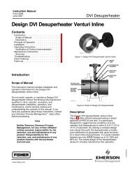
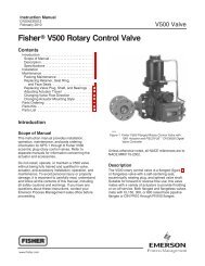
Instruction ManualD100397X012<strong>ES</strong> ValveDecember 2010<strong>Fisher</strong> <strong>ES</strong> <strong>and</strong> <strong>EAS</strong> easy‐e <strong>Valves</strong><strong>CL125</strong> <strong>through</strong> <strong>CL600</strong>ContentsIntroduction ................................. 1Scope of Manual ............................. 1Description ................................. 2Specifications ............................... 2Installation ................................... 2Maintenance ................................. 4Packing Lubrication .......................... 5Packing Maintenance ......................... 6Replacing Packing ........................ 6Trim Maintenance .......................... 11Disassembly ............................ 11Lapping Metal Seats ..................... 13Valve Plug Maintenance .................. 13Assembly .............................. 13ENVIRO‐SEAL Bellows Seal <strong>and</strong> Bonnet ........ 14Replacing a Plain or Extension Bonnet with anENVIRO‐SEAL Bellows Seal (Stem/BellowsAssembly) <strong>and</strong> Bonnet ................. 14Replacement of an Installed ENVIRO‐SEALBellows Seal (Stem/Bellows Assembly) .... 16Purging the ENVIRO‐SEAL BellowsSeal Bonnet .......................... 17Parts Ordering ............................... 17Parts Kits ................................... 17Parts List ................................... 19Figure 1. <strong>Fisher</strong> <strong>ES</strong> Valve with 657 ActuatorW2174‐3IntroductionScope of ManualThis instruction manual includes installation, maintenance, <strong>and</strong> parts information for NPS 1/2 <strong>through</strong> 8 <strong>Fisher</strong> <strong>ES</strong>valves, <strong>and</strong> NPS 1 <strong>through</strong> 6 <strong>EAS</strong> valves, <strong>through</strong> <strong>CL600</strong> ratings. Refer to separate manuals for instructions coveringthe actuator <strong>and</strong> accessories.Do not install, operate, or maintain an <strong>ES</strong> valve without being fully trained <strong>and</strong> qualified in valve, actuator, <strong>and</strong>accessory installation, operation, <strong>and</strong> maintenance. To avoid personal injury or property damage, it is important tocarefully read, underst<strong>and</strong>, <strong>and</strong> follow all the contents of this manual, including all safety cautions <strong>and</strong> warnings. If youhave any questions about these instructions, contact your Emerson Process Management sales office beforeproceeding.www.<strong>Fisher</strong>.com
<strong>ES</strong> ValveDecember 2010Instruction ManualD100397X012Table 1. SpecificationsEnd Connection StylesCast Iron <strong>Valves</strong>Flanged: <strong>CL125</strong> flat‐face or CL250 raised‐face flangesper ASME B16.1Steel <strong>and</strong> Stainless Steel <strong>Valves</strong>Flanged: CL150, 300, <strong>and</strong> 600 raised‐face or ring‐typejoint flanges per ASME B16.5Screwed or Socket Welding: All available ASME B16.11schedules that are consistent with <strong>CL600</strong> per ASMEB16.34Buttwelding: Consistent with ASME B16.25Shutoff ClassificationsSee table 2Flow CharacteristicsSt<strong>and</strong>ard Cages: Linear, quick opening, or equalpercentageWhisper Trim <strong>and</strong> WhisperFlo Cages: LinearFlow DirectionsSt<strong>and</strong>ard Cages: Normally upWhisper Trim <strong>and</strong> WhisperFlo Cages: Always upMaximum Inlet Pressure (1)Cast Iron <strong>Valves</strong>Flanged: Consistent with <strong>CL125</strong>B or 250Bpressure‐temperature ratings per ASME B16.1Steel <strong>and</strong> Stainless Steel <strong>Valves</strong>Flanged: Consistent with CL150, 300, <strong>and</strong> 600 (2)pressure‐temperature ratings per ASME B16.34Screwed or Welding: Consistent with <strong>CL600</strong>pressure‐temperature ratings per ASME B16.34Approximate WeightsVALVE SIZE, NPS1/2 <strong>and</strong> 3/41 <strong>and</strong> 1‐1/41‐1/222‐1/23468kg11142039455477459408WEIGHTPounds253045671001251703509001. The pressure/temperature limits in this manual <strong>and</strong> any applicable st<strong>and</strong>ard or code limitation for the valve should not be exceeded.2. Certain bonnet bolting material selections may require a <strong>CL600</strong> easy‐e valve assembly to be derated. Contact your Emerson Process Management sales office.DescriptionThese single‐port valves have cage guiding, quick‐change trim, <strong>and</strong> unbalanced push‐down‐to‐close valve plug action.Valve configurations are as follows:<strong>ES</strong>—Globe style valve (figure 1) with metal‐to‐metal seating as st<strong>and</strong>ard for all general applications over a wide rangeof pressure drops <strong>and</strong> temperatures, <strong>and</strong> metal‐to‐PTFE seating is optional for more stringent shutoff requirements.<strong>EAS</strong>—Angle valve version of <strong>ES</strong>, used to facilitate piping or in applications where a self draining valve body is required.SpecificationsTypical specifications for these valves are shown in table 1.InstallationWARNINGAlways wear protective gloves, clothing, <strong>and</strong> eyewear when performing any installation operations to avoid personalinjury.Personal injury or equipment damage caused by sudden release of pressure may result if the valve assembly is installedwhere service conditions could exceed the limits given in table 1 or on the appropriate nameplates. To avoid such injury ordamage, provide a relief valve for over‐pressure protection as required by government or accepted industry codes <strong>and</strong> goodengineering practices.2
Instruction ManualD100397X012<strong>ES</strong> ValveDecember 2010Check with your process or safety engineer for any additional measures that must be taken to protect against processmedia.If installing into an existing application, also refer to the WARNING at the beginning of the Maintenance section in thisinstruction manual.Table 2. Available Shutoff Classifications per ANSI/FCI 70‐2 <strong>and</strong> IEC 60534‐4SeatingMetalPTF<strong>ES</strong>hutoff ClassIV (st<strong>and</strong>ard)VVICAUTIONWhen ordered, the valve configuration <strong>and</strong> construction materials were selected to meet particular pressure, temperature,pressure drop, <strong>and</strong> controlled fluid conditions. Since some body/trim material combinations are limited in their pressuredrop <strong>and</strong> temperature ranges, do not apply any other conditions to the valve without first contacting your EmersonProcess Management sales office.Before installing the valve, inspect the valve <strong>and</strong> pipelines for any damage <strong>and</strong> any foreign material which may causeproduct damage.1. Before installing the valve, inspect the valve <strong>and</strong> associated equipment for any damage <strong>and</strong> any foreign material.2. Make certain the valve body interior is clean, that pipelines are free of foreign material, <strong>and</strong> that the valve isoriented so that pipeline flow is in the same direction as the arrow on the side of the valve.3. The control valve assembly may be installed in any orientation unless limited by seismic criteria. However, thenormal method is with the actuator vertical above the valve. Other positions may result in uneven valve plug <strong>and</strong>cage wear, <strong>and</strong> improper operation. With some valves, the actuator may also need to be supported when it is notvertical. For more information, consult your Emerson Process Management sales office.4. Use accepted piping <strong>and</strong> welding practices when installing the valve in the line. Internal elastomeric parts may stayin place during the welding procedure. For flanged valves, use a suitable gasket between the valve <strong>and</strong> pipelineflanges.CAUTIONDepending on valve body materials used, post weld heat treating may be required. If so, damage to internal elastomeric<strong>and</strong> plastic parts, as well as internal metal parts is possible. Shrunk‐fit pieces <strong>and</strong> threaded connections may also loosen. Ingeneral, if post weld heat treating is to be performed, all trim parts should be removed. Contact your Emerson ProcessManagement sales office for additional information.5. With a leak‐off bonnet construction, remove the pipe plugs (keys 14 <strong>and</strong> 16, figure 8) to hook up the leak‐offpiping. If continuous operation is required during inspection or maintenance, install a three‐valve bypass aroundthe control valve assembly.6. If the actuator <strong>and</strong> valve are shipped separately, refer to the actuator mounting procedure in the appropriateactuator instruction manual.WARNINGPersonal injury could result from packing leakage. Valve packing was tightened before shipment; however, the packingmight require some readjustment to meet specific service conditions.3
<strong>ES</strong> ValveDecember 2010Instruction ManualD100397X012<strong>Valves</strong> with ENVIRO‐SEAL live‐loaded packing or HIGH‐SEAL Heavy‐Duty live‐loaded packing will not require this initialre‐adjustment. See the <strong>Fisher</strong> instruction manuals titled ENVIRO‐SEAL Packing System for Sliding‐Stem <strong>Valves</strong> orHeavy‐Duty Live‐Loaded Packing System (as appropriate) for packing instructions. If you wish to convert your presentpacking arrangement to ENVIRO‐SEAL packing, refer to the retrofit kits listed in the Parts Kits sub‐section near the endof this manual.MaintenanceValve parts are subject to normal wear <strong>and</strong> must be inspected <strong>and</strong> replaced as necessary. Inspection <strong>and</strong> maintenancefrequency depends on the severity of service conditions. This section includes instructions for packing lubrication,packing maintenance, trim maintenance, <strong>and</strong> ENVIRO‐SEAL bellows seal replacement. All maintenance operationsmay be performed with the valve in the line.WARNINGAvoid personal injury or damage to property from sudden release of pressure or uncontrolled process fluid. Before startingdisassembly: Do not remove the actuator from the valve while the valve is still pressurized. Always wear protective gloves, clothing, <strong>and</strong> eyewear when performing any maintenance operations to avoid personalinjury. Disconnect any operating lines providing air pressure, electric power, or a control signal to the actuator. Be sure theactuator cannot suddenly open the valve. Use bypass valves or completely shut off the process to isolate the valve from process pressure. Relieve process pressureon both sides of the valve. Drain the process media from both sides of the valve. Vent the power actuator loading pressure <strong>and</strong> relieve any actuator spring compression. Use lock‐out procedures to be sure that the above measures stay in effect while you work on the equipment. The valve packing box may contain process fluids that are pressurized, even when the valve has been removed from thepipeline. Process fluids may spray out under pressure when removing the packing hardware or packing rings, or whenloosening the packing box pipe plug. Check with your process or safety engineer for any additional measures that must be taken to protect against processmedia.CAUTIONFollow instructions carefully to avoid damaging the product surfaces, which could result in damage to the product.NoteWhenever a gasket seal is disturbed by removing or shifting gasketed parts, a new gasket should be installed upon reassembly.This is necessary to ensure a good gasket seal since the used gasket may not seal properly.NoteIf the valve has ENVIRO‐SEAL or HIGH‐SEAL live‐loaded packing installed, refer to instruction manuals ENVIRO‐SEAL PackingSystem for Sliding‐Stem <strong>Valves</strong>, D101642X012, or HIGH‐SEAL Live‐Loaded Packing System, D101453X012, for packing4
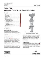
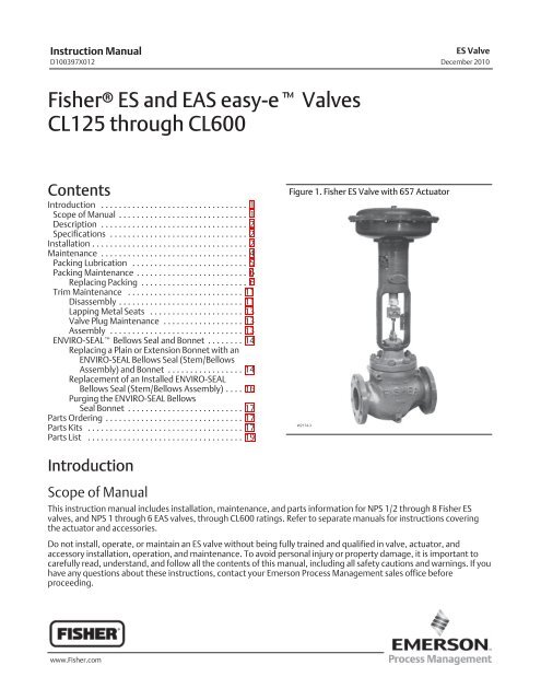
Instruction ManualD100397X012<strong>ES</strong> ValveDecember 2010instructions. Figure 9 shows a typical HIGH‐SEAL Packing system. Figures 10, 11, <strong>and</strong> 12 show typical ENVIRO‐SEAL packingsystems.If the valve has an ENVIRO‐SEAL bellows seal bonnet installed, refer to this manual. See the ENVIRO‐SEAL Bellows Seal <strong>and</strong> Bonnetsection for information on the bellows seal bonnet.Figure 2. Optional Lubricator <strong>and</strong> Lubricator/Isolating Valve10A9421‐AAJ5428‐DA0832‐2LUBRICATORLUBRICATOR/ISOLATING VALVETable 3. Body‐to‐Bonnet Bolt Torque GuidelinesVALVE SIZE, NPS BOLT TORQU<strong>ES</strong> (1, 4)<strong>ES</strong><strong>EAS</strong>SA193‐B7, SA193‐B8M (3) SA193‐B8M (2)Nm Lbfft Nm Lbfft1‐1/4 or less 1 129 95 64 471‐1/2, 1‐1/2 x 1, 2, or 2 x 1 2 or 2 x 1 96 71 45 332‐1/2 or 2‐1/2 x 1‐1/2 3 or 3 x 1‐1/2 129 95 64 473, 3 x 2, or 3 x 2‐1/2 4 or 4 x 2 169 125 88 654, 4 x 2‐1/2, or 4 x 3 6 or 6 x 2‐1/2 271 200 156 1156 ‐ ‐ ‐ 549 405 366 2708 ‐ ‐ ‐ 746 550 529 3901. Determined from laboratory tests.2. SA193‐B8M annealed.3. SA193‐B8M strain hardened.4. For other materials, contact your Emerson Process Management sales office for torques.Packing LubricationNoteENVIRO‐SEAL or HIGH‐SEAL packing does not require lubrication.WARNINGTo avoid personal injury or property damage resulting from fire or explosion, do not lubricate packing used in oxygenservice or in processes with temperatures over 260C (500F).If a lubricator or lubricator/isolating valve (figure 2) is provided for PTFE/composition or other packings that requirelubrication, it will be installed in place of the pipe plug (key 14, figure 8). Use a good quality silicon‐base lubricant.Packing used in oxygen service or in processes with temperatures over 260C (500F) should not be lubricated. To5
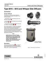
Instruction ManualD100397X012<strong>ES</strong> ValveDecember 2010Figure 3. PTFE V‐Ring Packing Arrangements for Plain <strong>and</strong> Extension BonnetsUPPER WIPER(KEY 12)UPPER WIPER(KEY 12)PACKINGFOLLOWER(KEY 13)FEMALEADAPTOR11FEMALEADAPTORPACKINGFOLLOWER(KEY 13)WASHER(KEY 10)SPRING(KEY 8)PACKING RINGMALEADAPTOR1111PACKING RINGMALEADAPTORSPACER(KEY 8)PACKING BOXRING (KEY 11)PACKING BOXRING (KEY 11)12A7837ALOWER WIPER11LOWER WIPERFOR S31600 OR S17400METAL PACKING BOX PARTSFOR ALL OTHER METAL PACKINGBOX PART MATERIALS1B2427NOTE:PART OF PACKING SET (KEY 6) (SEE TABLE IN PARTS LIST).SINGLE ARRANGEMENTSUPPER WIPER(KEY 12)PACKINGFOLLOWER(KEY 13)MALE ADAPTOR(KEY 31)PACKING RING(KEY 7)FEMALE ADAPTOR(KEY 32)LANTERN RING(KEY 8)PACKING BOXRING (KEY 11)12A8187-D 12A7814-D 12A7839-AASSEMBLY 1(POSITIVEPR<strong>ES</strong>SUR<strong>ES</strong>)ASSEMBLY 2(VACUUM)ASSEMBLY 1(POSITIVEPR<strong>ES</strong>SUR<strong>ES</strong>)ASSEMBLY 2(VACUUM)B1428‐3ASSEMBLY 3(POSITIVEPR<strong>ES</strong>SUR<strong>ES</strong>& VACUUM)ASSEMBLY 3(POSITIVEPR<strong>ES</strong>SUR<strong>ES</strong>& VACUUM)ASSEMBLY 1(POSITIVEPR<strong>ES</strong>SUR<strong>ES</strong>)ASSEMBLY 2(VACUUM)9.5 mm (3/8 INCH) STEM 12.7 mm (1/2 INCH) STEM 19.1, 25.4, or 31.8 mm(3/4, 1, OR 1‐1/4 INCH) STEMDOUBLE ARRANGEMENTSASSEMBLY 3(POSITIVEPR<strong>ES</strong>SUR<strong>ES</strong>& VACUUM)LOWER WIPER(KEY 30)7
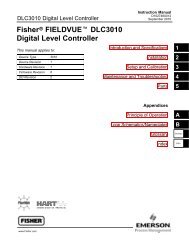
<strong>ES</strong> ValveDecember 2010Instruction ManualD100397X012Figure 4. PTFE Packing Arrangements for Use in ENVIRO‐SEAL Bellows Seal BonnetsUPPER WIPER(KEY 12)BUSHING (KEY 13)PACKING SET: (KEY 6)FEMALE ADAPTORPACKING RINGMALE ADAPTORTHRUSTRING(KEY 39)SPRING(KEY 8)THRUSTRINGSPACER(KEY 8)SPACER(KEY 8)12B4182-A SHT 1 12B4185-A SHT 1 12B4182-A SHT 2 12B4185-A SHT 2(KEY 39)12.7 mm9.5 mm12.7 mm 9.5 mm(1/2 INCH)(3/8 INCH) (1/2 INCH) (3/8 INCH)STEMSTEMSTEM STEMFOR S31600 (316 SST)PACKING BOX PARTSSINGLE ARRANGEMENTSFOR ALL PACKING BOXMATERIALS EXCEPT S31600BUSHING(KEY 13)BUSHING(KEY 13)SPACER(KEY 8)UPPER WIPER(KEY 12)BUSHING (KEY 13)PACKING SET: (KEY 6)FEMALE ADAPTORPACKING RINGMALE ADAPTORTHRUSTRING12B4183-A (KEY 39)18A0906-D 18A5338-A9.5 mm(3/8 INCH)STEMA5863‐112.7 mm(1/2 INCH)STEM FORNPS 2 VALV<strong>ES</strong>DOUBLE ARRANGEMENTSSPACER(KEY 8)12.7 mm(1/2 INCH)STEM FORNPS 3 AND 4VALV<strong>ES</strong>4. Loosen the packing flange nuts (key 5, figure 8) so that the packing is not tight on the valve stem. Remove anytravel indicator parts from the valve stem threads.CAUTIONAvoid damage to the seating surface caused by the valve plug <strong>and</strong> stem assembly dropping from the bonnet after beinglifted part way out. When lifting the bonnet, temporarily install a valve stem locknut on the valve stem. This locknut willprevent the valve plug <strong>and</strong> stem assembly from dropping out of the bonnet.If the cage starts to lift with the bonnet, tap it with a plastic mallet, or other soft material, to be sure it stays in the valve.5. Completely remove the cap screws (not shown) or hex nuts (key 16; figure 13, 14, or 15) that bolt the bonnet <strong>and</strong>valve together <strong>and</strong> carefully lift the bonnet off.6. Remove the locknut <strong>and</strong> separate the valve plug <strong>and</strong> stem from the bonnet. Set the parts on a protective surface toprevent damage to gasket or seating surfaces.8
Instruction ManualD100397X012<strong>ES</strong> ValveDecember 201015. Mount the actuator on the valve assembly <strong>and</strong> reconnect the actuator <strong>and</strong> valve stem according to the procedurein the appropriate actuator instruction manual.Trim MaintenanceWARNINGRefer to the WARNING at the beginning of the Maintenance section in this instruction manual.CAUTIONIn the following applicable procedures, to avoid damaging parts, do not grip the bellows shroud or other parts of thestem/bellows assembly. Grip only the flat areas on the stem where it extends out of the top of the bellows shroud.Except where indicated, key numbers in this section are referenced in figure 13 for st<strong>and</strong>ard NPS 1/2 <strong>through</strong> 6constructions, figure 14 for NPS 8 <strong>ES</strong> valves, figure 15 for Whisper Trim III cage detail, <strong>and</strong> figure 16 for WhisperFlotrim.Disassembly1. Remove the actuator <strong>and</strong> the bonnet according to steps 1 <strong>through</strong> 6 of the Replacing Packing procedure of theMaintenance section.Table 4. Recommended Torque for Packing Flange Nuts (Not for Spring‐Loaded Packing)GRAPHITE TYPE PACKINGPTFE TYPE PACKINGVALVE STEM DIAMETER PR<strong>ES</strong>S‐UREMinimum Torque Maximum Torque Minimum Torque Maximum TorqueRATINGmm Inches Nm Lbfin Nm Lbfin Nm Lbfin Nm Lbfin<strong>CL125</strong>,1503 24 5 48 1 12 3 249.5 3/8 CL250,3004 36 7 60 2 18 3 30<strong>CL600</strong> 5 48 8 72 3 24 4 36<strong>CL125</strong>,1505 48 8 72 3 24 4 3612.7 1/2 CL250,3007 60 10 84 3 30 5 42<strong>CL600</strong> 10 84 14 120 5 42 7 60<strong>CL125</strong>,15011 96 16 144 5 48 8 7219.1 3/4 CL250,30014 120 20 180 7 60 10 90<strong>CL600</strong> 20 180 30 264 10 90 15 13225.4 1CL300 24 216 37 324 12 108 16 144<strong>CL600</strong> 34 300 50 444 16 144 24 21631.8 1‐1/4CL300 33 288 49 432 16 144 24 216<strong>CL600</strong> 45 396 66 588 22 192 33 28811
<strong>ES</strong> ValveDecember 2010Instruction ManualD100397X012WARNINGTo avoid personal injury due to leaking fluid, avoid damaging gasket sealing surfaces. The surface finish of the valve stem(key 7) is critical for making a good packing seal. The inside surface of the cage or cage/baffle assembly (key 3), or cageretainer (key 31), is critical for smooth operation of the valve plug. The seating surfaces of the valve plug (key 2) <strong>and</strong> seatring (key 9) are critical for proper shutoff. Unless inspection reveals otherwise, assume all these parts are in good condition<strong>and</strong> protect them accordingly.2. Packing parts can be removed if desired. Replace these parts as described in the Replacing Packing procedure.Remove the load ring (key 26) from an NPS 8 <strong>ES</strong> valve, or the cage adaptor (key 4) from any restricted trim valve,<strong>and</strong> wrap it for protection.3. Lift the valve plug <strong>and</strong> stem assembly out of the valve <strong>and</strong> set it on a protective surface. If the valve plug is to bereused, protect the valve plug seating surface to prevent scratches. On an NPS 6 <strong>ES</strong> valve with Whisper Trim III cageor WhisperFlo trim, also remove the bonnet spacer (key 32) <strong>and</strong> bonnet gasket (key 10) on top of the spacer. Thenon any construction with a cage retainer (key 31), remove the cage retainer <strong>and</strong> its associated gaskets.A Whisper Trim III <strong>and</strong> WhisperFlo trim cage retainer has two 3/8 inch‐16 UNC tappings in which screws or bolts can beinstalled for lifting.4. Remove the cage or cage/baffle assembly (key 3), the associated gaskets (keys 10, 11, <strong>and</strong> 12), <strong>and</strong> shim (key 51for the <strong>ES</strong> valve, key 27 for the <strong>EAS</strong> valve). If the cage is stuck in the valve body, use a rubber mallet to strike theexposed portion of the cage at several points around its circumference.5. Remove the seat ring or liner (key 9) or disk seat (key 22), seat ring gasket (key 13), <strong>and</strong> the seat ring adaptor (key5) <strong>and</strong> adaptor gasket (key 14) where used in a restricted trim seat ring construction. PTFE seat constructions use adisk (key 23) s<strong>and</strong>wiched between the disk seat <strong>and</strong> disk retainer (key 21).6. Inspect parts for wear or damage which would prevent proper operation of the valve. Replace or repair trim partsaccording to the following procedure for lapping metal seats or other valve plug maintenance procedures asappropriate.Table 5. Valve Stem Connection Torque <strong>and</strong> Pin ReplacementVALVE STEM CONNECTION (VSC) BOLT TORQUE, MINIMUM TO MAXIMUM HOLE SIZEmm Inches Nm Lbfft mm Inch9.512.719.125.431.83/81/23/411‐1/440‐4781‐115237‐339420‐481827‐90825‐3560‐85175‐250310‐355610‐6702.41 ‐ 2.463.20 ‐ 3.254.80 ‐ 4.886.38 ‐ 6.456.38 ‐ 6.450.095 ‐ 0.0970.126 ‐ 0.1280.189 ‐ 0.1920.251 ‐ 0.2540.251 ‐ 0.254Table 6. St<strong>and</strong>ard Material DesignationsSt<strong>and</strong>ard DesignationCoCr‐A Hardfacing AlloyR30006S17400 SSTS31600 SSTS41000, S41600, CA15WCC Carbon Steel CastingCommon Name or Trade NameCoCr‐AAlloy 6 Casting17‐4PH Stainless Steel316 Stainless Steel13Cr 400‐Series SSTWCCCAUTIONTo avoid damaging the ENVIRO‐SEAL bellows seal bonnet assembly, do not attempt to lap the metal seating surfaces. Thedesign of the assembly prevents rotation of the stem <strong>and</strong> any forced lapping rotation will damage internal components ofthe ENVIRO‐SEAL bellows seal bonnet.12
Instruction ManualD100397X012<strong>ES</strong> ValveDecember 2010Lapping Metal SeatsA certain amount of leakage should be expected with metal‐to‐metal seating in any valve body. If the leakagebecomes excessive, however, the condition of the seating surfaces of the valve plug <strong>and</strong> seat ring can be improved bylapping. (Deep nicks should be machined out rather than ground out.) Use a good quality lapping compound of amixture of 280 to 600‐grit. Apply the compound to the bottom of the valve plug.Assemble the valve to the extent that the cage <strong>and</strong> the cage retainer <strong>and</strong> bonnet spacer (if used) are in place <strong>and</strong> thebonnet is bolted to the valve body. A simple h<strong>and</strong>le can be made from a piece of strap iron locked to the valve plugstem with nuts. Rotate the h<strong>and</strong>le alternately in each direction to lap the seats. After lapping, remove the bonnet <strong>and</strong>clean the seat surfaces. Completely assemble as described in the assembly portion of the trim maintenance procedure<strong>and</strong> test the valve for shutoff. Repeat the lapping procedure if leakage is still excessive.CAUTIONTo avoid weakening the stem or adaptor that may cause failure in service, never reuse an old stem or adaptor with a newvalve plug. Using an old stem or adaptor with a new plug requires drilling a new pin hole in the stem (or adaptor in case anENVIRO‐SEAL bellows seal bonnet is being used), which will weaken the stem. However, a used valve plug may be reusedwith a new stem or adaptor.Valve Plug MaintenanceExcept where indicated, key numbers are referenced in figure 13 for NPS 1/2 <strong>through</strong> 6 constructions, figure 14 forNPS 8 <strong>ES</strong> valves, figure 15 for Whisper Trim III cage detail, <strong>and</strong> figure 16 for WhisperFlo trim.1. Remove the valve plug (key 2) according to the disassembly portion of the trim maintenance procedure.2. To replace the valve stem (key 7), drive out the pin (key 8). Unscrew the valve plug from the stem or adaptor.3. To replace the adaptor (key 24, figure 8) on ENVIRO‐SEAL bellows seal bonnets, place the plug stem assembly <strong>and</strong>valve plug in a soft‐jaw chuck or other type of vise so that the jaws grip a portion of the valve plug that is not aseating surface. Drive out or drill out the pin (key 36, figure 8). Reverse the plug stem assembly in the soft‐jawchuck or vise. Grip the flat areas on the valve stem just below the threads for the actuator/stem connection.Unscrew the valve plug/adaptor assembly (key 24, figure 8) from the valve stem assembly (key 20, figure 8).4. Screw the stem or adaptor into the valve plug. Tighten to the torque value given in table 5. Refer to table 5 to selectthe proper hole size. Drill <strong>through</strong> the stem or adaptor, using the hole in the valve plug as a guide. Remove anychips or burrs <strong>and</strong> drive in a new pin to lock the assembly.5. For ENVIRO‐SEAL bellows seal bonnets, grip the flats of the stem extending out of the top of the bellows shroudwith a soft‐jaw chuck or other type of vise. Screw the valve plug/adaptor assembly onto the valve stem. Tighten asnecessary to align the pin hole in the stem with one of the holes in the adaptor. Secure the adaptor to the stem witha new pin.AssemblyExcept where indicated, key numbers are referenced in figure 13 for st<strong>and</strong>ard NPS 1/2 <strong>through</strong> 6 constructions, figure14 for NPS 8 <strong>ES</strong> valves, figure 15 for Whisper Trim III cage detail, <strong>and</strong> figure 16 for WhisperFlo trim.1. With a restricted trim seat ring construction, install the adaptor gasket (key 14) <strong>and</strong> seat ring adaptor (key 5).2. Install the seat ring gasket (key 13), seat ring or liner (key 9), or disk seat (key 22). With a PTFE seat construction,install the disk <strong>and</strong> disk retainer (keys 21 <strong>and</strong> 23).3. Install the cage or cage/baffle assembly (key 3). Any rotational orientation of the cage or assembly with respect tothe valve is acceptable. A Whisper Trim III cage designated by level A3, B3, or C3 may be installed with either end13
<strong>ES</strong> ValveDecember 2010Instruction ManualD100397X012up. The level D3 cage/baffle assembly, however, must be installed with the hole pattern end next to the seat ring. Ifa cage retainer (key 31) is to be used, place it on top of the cage.4. Slide the valve plug (key 2) <strong>and</strong> stem assembly, or valve plug <strong>and</strong> ENVIRO‐SEAL bellows seal assembly, into thecage.5. Place the gaskets (key 10, or keys 11, 12 <strong>and</strong> 14, if used) <strong>and</strong> the shim (key 27 or key 51) on top of the cage or cageretainer. If there is a cage adaptor (key 4) or a bonnet spacer (key 32), set it on the cage or cage retainer gaskets<strong>and</strong> place another flat sheet gasket (key 10) on top of the adaptor or spacer. If there is only a cage retainer, placeanother flat sheet gasket on the retainer.6. With an NPS 8 <strong>ES</strong> valve, install the load ring (key 26).CAUTIONTo avoid damaging packing with the valve stem threads, use care when installing the bonnet if the packing was notremoved from the bonnet.Table 7. Recommended Torque for ENVIRO‐SEAL Bellows Seal Packing Flange NutsVALVE SIZE VALVE STEM DIAMETER THROUGH PACKING MINIMUM TORQUE MAXIMUM TORQUENPS Inch Nm Lbfin Nm Lbfin1/2 ‐ 2 1/2 3 24 5 483 ‐ 4 1 7 60 10 847. Mount the bonnet on the valve <strong>and</strong> complete assembly according to steps 10 <strong>through</strong> 14 of the Replacing Packingprocedure, omitting steps 11 <strong>and</strong> 12 if new packing is not being installed, <strong>and</strong> being sure to observe the note priorto step 11.ENVIRO‐SEAL Bellows Seal <strong>and</strong> BonnetReplacing a Plain or Extension Bonnet with an ENVIRO‐SEAL Bellows Seal (Stem/BellowsAssembly) <strong>and</strong> Bonnet1. Remove the actuator <strong>and</strong> bonnet according to steps 1 <strong>through</strong> 6 of the Replacing Packing procedure of theMaintenance section.2. With care, remove the valve plug <strong>and</strong> stem assembly from the valve body. If necessary, lift out the cage, also.CAUTIONTo prevent possible product damage, cover the opening in the valve in the following procedure to protect the sealingsurfaces <strong>and</strong> to prevent foreign material from getting into the valve body cavity.3. Remove <strong>and</strong> discard the existing bonnet gasket. Cover the valve body opening to protect sealing surfaces <strong>and</strong> toprevent foreign material from entering the valve body cavity.NoteThe ENVIRO‐SEAL stem/bellows assembly for easy‐e valves is available only with a threaded <strong>and</strong> drilled plug/adaptor/stemconnection. The existing valve plug can be reused with the new stem/bellows assembly or a new plug can be installed.14
Instruction ManualD100397X012<strong>ES</strong> ValveDecember 20104. Inspect the existing valve plug. If the plug is in good condition, it can be reused with the new ENVIRO‐SEALstem/bellows assembly. To remove the existing valve plug from the stem, first, place the existing plug stemassembly <strong>and</strong> valve plug in a soft‐jaw chuck or other type of vise so that the jaws grip a portion of the valve plugthat is not a seating surface. Drive out or drill out the pin (key 8).5. Then, reverse the plug stem assembly in the soft‐jaw chuck or vise. Grip the valve stem in an appropriate place <strong>and</strong>unscrew the existing plug from the valve stem.CAUTIONWhen installing a valve plug on the ENVIRO‐SEAL stem/bellows assembly, the valve stem must not be rotated. Damage tothe bellows may result.To avoid damaging parts, do not grip the bellows shroud or other parts of the stem/bellows assembly. Grip only the flatareas on the stem where it extends out of the top of the bellows shroud.NoteThe ENVIRO‐SEAL stem/bellows assembly has a one‐piece stem.6. To attach the valve plug to the stem of the new ENVIRO‐SEAL stem/bellows assembly, it is necessary to first attachthe plug to the adaptor (key 24). Locate the adaptor. Notice that a hole has not been drilled in the threads wherethe plug screws onto the adaptor. Secure the valve plug in a soft‐jaw chuck or other type of vise. Do not grip theplug on any seating surface. Position the plug in the chuck or vise for easy threading of the adaptor. Thread theadaptor into the valve plug <strong>and</strong> tighten to the appropriate torque value.7. Select the proper size of drill bit <strong>and</strong> drill <strong>through</strong> the adaptor using the hole in the valve plug as a guide. Removeany metal chips or burrs <strong>and</strong> drive in a new pin to lock the plug/adaptor assembly together.8. Attach the plug/adaptor assembly to the ENVIRO‐SEAL stem/bellows assembly by first securing the stem/bellowsassembly in a soft‐jaw chuck or other type of vise so that the jaws of the chuck or vise grip the flats of the stemextending out of the top of the bellows shroud. Screw the valve plug/adaptor assembly onto the valve stem.Tighten as necessary to align the pin hole in the stem with one of the holes in the adaptor. Secure the adaptor tothe stem with a new pin.9. Inspect the seat ring (key 9) <strong>and</strong> soft seat parts (keys 21, 22, <strong>and</strong> 23). Replace, if necessary.10. Place a new gasket (key 10) into the valve body in place of the bonnet gasket. Install the new stem/bellowsassembly with valve plug/adaptor by placing it into the valve body on top of the new bellows gasket.11. Place a new gasket (key 22) over the stem/bellows assembly. Place the new ENVIRO‐SEAL bonnet over thestem/bellows assembly.12. Properly lubricate the bonnet stud bolts. Install <strong>and</strong> tighten the bonnet hex nuts to the proper torque.13. Install new packing <strong>and</strong> the metal packing box parts according to the appropriate arrangement in figure 3.14. Install the packing flange. Properly lubricate the packing flange stud bolts <strong>and</strong> the faces of the packing flange nuts.For ENVIRO‐SEAL or HIGH‐SEAL live‐loaded packing, refer to the note at the beginning of the Maintenance section.For graphite packing, tighten the packing flange nuts to the maximum recommended torque shown in table 7. Then,loosen the packing flange nuts, <strong>and</strong> retighten them to the recommended minimum torque shown in table 7.For other packing types, tighten the packing flange nuts alternately in small equal increments until one of the nutsreaches the minimum recommended torque shown in table 7. Then, tighten the remaining flange nuts until thepacking flange is level <strong>and</strong> at a 90‐degree angle to the valve stem.15. Install travel indicator parts, stem locknuts, <strong>and</strong> mount the actuator on the valve body according to the procedurein the appropriate actuator instruction manual.15
<strong>ES</strong> ValveDecember 2010Instruction ManualD100397X012Replacement of an Installed ENVIRO‐SEAL Bellows Seal (Stem/Bellows Assembly)1. Remove the actuator <strong>and</strong> bonnet according to steps 1 <strong>through</strong> 6 of the Replacing Packing procedure of theMaintenance section.CAUTIONTo prevent possible product damage, cover the opening in the valve in the following procedure to protect the sealingsurfaces <strong>and</strong> to prevent foreign material from getting into the valve body cavity.2. With care, remove the ENVIRO‐SEAL stem/bellows assembly. If necessary, lift out the cage, also. Remove <strong>and</strong>discard the existing bonnet gasket <strong>and</strong> bellows gasket. Cover the valve body opening to protect sealing surfaces<strong>and</strong> to prevent foreign material from entering the valve body cavity.NoteThe ENVIRO‐SEAL stem/bellows assembly for easy‐e valves is available only with a threaded <strong>and</strong> drilled plug/adaptor/stemconnection. The existing valve plug can be reused with the new stem/bellows assembly or a new plug can be installed.3. Inspect the existing valve plug. If the plug is in good condition, it can be reused with the new stem/bellowsassembly.CAUTIONWhen removing/installing a valve plug on the ENVIRO‐SEAL stem/bellows assembly, the valve stem must not be rotated.Damage to the bellows may result.To avoid damaging parts, do not grip the bellows shroud or other parts of the stem/bellows assembly. Grip only the flatareas on the stem where it extends out of the top of the bellows shroud.NoteThe ENVIRO‐SEAL stem/bellows assembly has a one‐piece stem.4. To remove the existing valve plug from the stem, first, place the existing plug stem assembly <strong>and</strong> valve plug in asoft‐jaw chuck or other type of vise so that the jaws grip a portion of the valve plug that is not a seating surface.Drive out or drill out the pin.5. Then, reverse the plug stem assembly in the soft‐jaw chuck or vise. Grip the flat areas on the valve stem just belowthe threads for the actuator/stem connection. Unscrew the existing plug from the valve stem.6. To attach either the existing valve plug or a new one to the stem of the new ENVIRO‐SEAL stem/bellows assembly,it is necessary to first attach the plug to the adaptor. Locate the adaptor. Notice that a hole has not been drilled inthe threads where the plug screws onto the adaptor. Secure the valve plug in a soft‐jaw chuck or other type of vise.Do not grip the plug on any seating surface. Position the plug in the chuck or vise for easy threading of the adaptor.Thread the adaptor into the valve plug <strong>and</strong> tighten to the appropriate torque value.7. Complete the installation by following steps 7 <strong>through</strong> 9 <strong>and</strong> steps 12 <strong>through</strong> 15 of the ENVIRO‐SEAL Bellows Seal<strong>and</strong> Bonnet installation instructions given above.16
Instruction ManualD100397X012<strong>ES</strong> ValveDecember 2010Purging the ENVIRO‐SEAL Bellows Seal BonnetThe ENVIRO‐SEAL bellows seal bonnet has been designed so that it can be purged or leak tested. Refer to figure 8 foran illustration of an ENVIRO‐SEAL bellows seal bonnet, <strong>and</strong> perform the following steps for purging or leak testing.1. Remove the two diametrically opposed pipe plugs (key 16).2. Connect a purging fluid to one of the pipe plug connections.3. Install appropriate piping or tubing in the other pipe plug connection to pipe away the purging fluid or to make aconnection to an analyzer for leak testing.4. When purging or leak testing has been completed, remove the piping or tubing <strong>and</strong> reinstall the pipe plugs (key16).Parts OrderingEach body‐bonnet assembly is assigned a serial number which can be found on the valve. This same number alsoappears on the actuator nameplate when the valve is shipped from the factory as part of a control valve assembly.Refer to the serial number when contacting your Emerson Process Management sales office for technical assistance.When ordering replacement parts, refer to the serial number <strong>and</strong> to the eleven‐character part number for each partrequired from the following parts kit or parts list information.Refer to table 6 for st<strong>and</strong>ard <strong>and</strong> common material designations.WARNINGUse only genuine <strong>Fisher</strong> replacement parts. Components that are not supplied by Emerson Process Management should not,under any circumstances, be used in any <strong>Fisher</strong> valve, because they may void your warranty, might adversely affect theperformance of the valve, <strong>and</strong> could cause personal injury <strong>and</strong> property damage.NoteNeither Emerson, Emerson Process Management, nor any of their affiliated entities assumes responsibility for the selection, use, ormaintenance of any product. Responsibility for the selection, use, <strong>and</strong> maintenance of any product remains with the purchaser <strong>and</strong>end user.Parts KitsNoteKits do not apply to alloy C (N10276 <strong>and</strong> CW2M), Alloy 20 (N08020 <strong>and</strong> CN7M), or alloy 400 (N04400 <strong>and</strong> M35‐1) trims.17
<strong>ES</strong> ValveDecember 2010Instruction ManualD100397X012Gasket KitsGasket Kits (includes keys 10, 11, 12, 13, <strong>and</strong> 51); plus 14 <strong>and</strong> 20 on Some Restricted Capacity <strong>Valves</strong>D<strong>ES</strong>CRIPTIONFull Capacity <strong>Valves</strong>NPS 1/2, 3/4, 1, <strong>and</strong> 1‐1/4 (NPS 1 <strong>EAS</strong>)NPS 1‐1/2 (NPS 2 <strong>EAS</strong>)NPS 2NPS 2‐1/2 (NPS 3 <strong>EAS</strong>)NPS 3 (NPS 4 <strong>EAS</strong>)NPS 4 (NPS 6 <strong>EAS</strong>)NPS 6NPS 8Restricted Capacity <strong>Valves</strong>w/ Metal SeatingNPS 1‐1/2 x 1 (NPS 2 x 1 <strong>EAS</strong>)NPS 2 x 1NPS 2‐1/2 x 1‐1/2 (NPS 3 x 1‐1/2 <strong>EAS</strong>)NPS 3 x 2 (NPS 4 x 2 <strong>EAS</strong>)NPS 4 x 2‐1/2 (NPS 6 x 2‐1/2 <strong>EAS</strong>)PART NUMBER-198 to 593C(-325 to 1100F)RGASKETX162RGASKETX172RGASKETX182RGASKETX192RGASKETX202RGASKETX212RGASKETX222RGASKETX232RGASKETX242RGASKETX252RGASKETX262RGASKETX272RGASKETX282Packing KitsSt<strong>and</strong>ard Packing Kits (Non Live‐Loaded)Stem Diameter, mm (Inches)Yoke Boss Diameter, mm (Inches)9.5 (3/8)54 (2‐1/8)12.7 (1/2)71 (2‐13/16)19.1 (3/4)90 (3‐9/16)PTFE (Contains keys 6, 8, 10, 11, <strong>and</strong> 12) RPACKX00012 RPACKX00022 RPACKX00032Double PTFE (Contains keys 6, 8, 11, <strong>and</strong> 12) RPACKX00042 RPACKX00052 RPACKX00062PTFE/Composition (Contains keys 7, 8, 11, <strong>and</strong> 12) RPACKX00072 RPACKX00082 RPACKX00092Single Graphite Ribbon/Filament (Contains keys 7 [ribbon ring], 7 [filament ring], 8, <strong>and</strong> 11) RPACKX00102 RPACKX00112 RPACKX00122Single Graphite Ribbon/Filament (Contains keys 7 [ribbon ring], 7 [filament ring]) RPACKX00132 RPACKX00142 RPACKX00152Double Graphite Ribbon/Filament (Contains keys 7 [ribbon ring], 7 [filament ring], 8, <strong>and</strong> 11) RPACKX00162 RPACKX00172 RPACKX00182ENVIRO‐SEAL Packing Retrofit KitsRetrofit kits include parts to convert valves with existing st<strong>and</strong>ard bonnets to the ENVIRO‐SEAL packing boxconstruction.Refer to figure 10 for key numbers for PTFE packing, to figure 11 for key numbers for Graphite ULF packing, <strong>and</strong> tofigure 12 for key numbers for duplex packing.PTFE kits include keys 200, 201, 211, 212, 214, 215, 217, 218, tag, <strong>and</strong> cable tie. Graphite ULF kits include keys 200,201, 207, 208, 209, 210, 211, 212, 214, 216, 217, tag, <strong>and</strong> cable tie. Duplex kits include keys 200, 201, 207, 209, 211,212, 214, 215, 216, 217, tag, <strong>and</strong> cable tie.Stems <strong>and</strong> packing box constructions that do not meet <strong>Fisher</strong> stem finish specifications, dimensional tolerances, <strong>and</strong>design specifications may adversely alter the performance of this packing kit.For part numbers of individual components in the ENVIRO‐SEAL packing kits, refer to instruction manual ENVIRO‐SEALPacking System for Sliding‐Stem <strong>Valves</strong>, D101642X012.18
Instruction ManualD100397X012<strong>ES</strong> ValveDecember 2010ENVIRO‐SEAL Packing Retrofit KitsPACKINGMATERIAL9.5 (3/8)54 (2‐1/8)STEM DIAMETER AND YOKE BOSS DIAMETER, mm (INCH)12.7 (1/2)71 (2‐13/16)19.1 (3/4)90 (3‐9/16)25.4 (1)127 (5)31.8 (1‐1/4)127 (5, 5H)Double PTFE RPACKXRT012 RPACKXRT022 RPACKXRT032 RPACKXRT042 RPACKXRT052Graphite ULF RPACKXRT262 RPACKXRT272 RPACKXRT282 RPACKXRT292 RPACKXRT302Duplex RPACKXRT212 RPACKXRT222 RPACKXRT232 RPACKXRT242 RPACKXRT252ENVIRO‐SEAL Packing Repair KitsRepair kits include parts to replace the “soft” packing materials in valves that already have ENVIRO‐SEAL packingarrangements installed or in valves that have been upgraded with ENVIRO‐SEAL retrofit kits.Refer to figure 10 for key numbers for PTFE packing, to figure 11 for key numbers for Graphite ULF packing, <strong>and</strong> tofigure 12 for key numbers for duplex packing.PTFE repair kits include keys 214, 215, <strong>and</strong> 218. Graphite ULF repair kits include keys 207, 208, 209, 210, <strong>and</strong> 214.Duplex repair kits include keys 207, 209, 214, <strong>and</strong> 215.Stems <strong>and</strong> packing box constructions that do not meet <strong>Fisher</strong> stem finish specifications, dimensional tolerances, <strong>and</strong>design specifications may adversely alter the performance of this packing kit.For part numbers of individual components in the ENVIRO‐SEAL packing kits, refer to instruction manual ENVIRO‐SEALPacking System for Sliding‐Stem <strong>Valves</strong>, D101642X012.ENVIRO‐SEAL Packing Repair KitsStem Diameter, mm (Inches)Yoke Boss Diameter, mm (Inches)9.5 (3/8)54 (2‐1/8)12.7 (1/2)71 (2‐13/16)19.1 (3/4)90 (3‐9/16)25.4 (1)127 (5)31.8 (1‐1/4)127 (5, 5H)Double PTFE (Contains keys 214, 215, & 218) RPACKX00192 RPACKX00202 RPACKX00212 RPACKX00222 RPACKX00232Graphite ULF (Contains keys 207, 208, 209, 210, <strong>and</strong> 214) RPACKX00592 RPACKX00602 RPACKX00612 RPACKX00622 RPACKX00632Duplex (Contains keys 207, 209, 214, <strong>and</strong> 215) RPACKX00292 RPACKX00302 RPACKX00312 RPACKX00322 RPACKX00332Parts ListNotePart numbers are shown for recommended spares only. For partnumbers not shown, contact your Emerson Process Management salesoffice.Bonnet (figures 3‐12)Key Description Part Number1 Bonnet/ENVIRO‐SEAL bellows seal bonnetIf you need a bonnet or an ENVIRO‐SEAL bellows sealbonnet as a replacement part, order by valve size <strong>and</strong>stem diameter, serial number, <strong>and</strong> desired material.2 Extension Bonnet Baffle3 Packing Flange3 ENVIRO‐SEAL bellows seal packing flangeKey Description Part Number4 Packing Flange Stud4 ENVIRO‐SEAL bellows seal stud bolt5 Packing Flange Nut5 ENVIRO‐SEAL bellows seal hex nut6* Packing set, PTFE see following table6* ENVIRO‐SEAL bellows seal packing setPTFE for 9.5 mm (3/8 inch) stem (1 req'dfor single packing, 2 req'd for doublepacking)12A9016X0126* ENVIRO‐SEAL bellows seal packing set (cont'd)PTFE for NPS 2 with 12.7 mm (1/2 inch)stem (2 req'd for double packing)12A9016X012PTFE for NPS 3 <strong>and</strong> 4 with 12.7 mm(1/2 inch) stem (2 req'd for doublepacking)12A8832X0127* Packing ring, PTFE composition see following table7* ENVIRO‐SEAL bellows seal packing ringfor low chloride graphite ribbon/filamentpacking arrangementRibbon packing ring for 9.5 mm (3/8 inch)*Recommended spare parts19
<strong>ES</strong> ValveDecember 2010Instruction ManualD100397X012Key Description Part Number<strong>and</strong> NPS 2 with 12.7 mm (1/2 inch) stem(4 req'd) 18A0908X012Filament packing ring for 9.5 mm(3/8 inch) <strong>and</strong> NPS 2 with 12.7 mm(1/2 inch) stem (4 req'd) 1P3905X0172Ribbon packing ring for NPS 3 <strong>and</strong> 4with 12.7 mm (1/2 inch) stem (4 req'd) 18A0918X012Filament packing ring for NPS 3 <strong>and</strong> 4with 12.7 mm (1/2 inch) stem (4 req'd) 14A0915X0428 Spring8 Lantern ring8 ENVIRO‐SEAL bellows seal spring8 ENVIRO‐SEAL bellows seal spacer10 Special washer11* Packing Box Ring9.5 mm (3/8 inch) stem,316 stainless steel 1J87313507212.7 mm (1/2 inch) stem,316 stainless steel 1J87323507219.1 mm (3/4 inch) stem,316 stainless steel 1J87333507225.4 mm (1 inch) stem, 17‐4PHstainless steel1J87343507231.8 mm (1‐1/4 inch) stem, 17‐4PHstainless steel1J87353507212* Upper Wiper, felt9.5 mm (3/8 inch) stem 1J87260633212.7 mm (1/2 inch) stem 1J87270633219.1 mm (3/4 inch) stem 1J87280633225.4 mm (1 inch) stem 1J87290633231.8 mm (1‐1/4 inch) stem 1J87300633212* ENVIRO‐SEAL bellows seal upper wiperFor 9.5 mm (3/8 inch) <strong>and</strong> NPS 2 with 12.7 mm(1/2 inch) stem 18A0868X012For NPS 3 <strong>and</strong> 4 with 12.7 mm (1/2 inch)stem18A0870X01213* Packing Follower, 316 stainless steel9.5 mm (3/8 inch) stem 1E94393507212.7 mm (1/2 inch) stem 1E94433507219.1 mm (3/4 inch) stem 1E94473507225.4 mm (1 inch) stem 1H98233507231.8 mm (1‐1/4 inch) stem 1H99843507213* ENVIRO‐SEAL bellows seal bushingFor 9.5 mm (3/8 inch) stem (1 req'd),for NPS 2 with 12.7 mm (1/2 inch) stem(2 req'd)S31600/PTFE18A0820X012R3000618A0819X012S31600/Cr Ct11B1155X012For NPS 3 <strong>and</strong> 4 with 12.7 mm (1/2 inch)stem (1 req'd)S31600/PTFE18A0824X012R3000618A0823X012S31600/Cr Ct11B1157X01213* ENVIRO‐SEAL bellows seal bushing/linerFor 9.5 mm (3/8 inch) stem (1 req'd),for NPS 2 with 12.7 mm (1/2 inch) stem(2 req'd)N10276 bushing, PTFE/glass liner12B2713X012N10276 bushing, PTFE/carbon liner12B2713X042Key Description Part NumberFor NPS 3 <strong>and</strong> 4 with 12.7 mm (1/2 inch)stem (1 req'd)N10276 bushing, PTFE/glass liner12B2715X012N10276 bushing, PTFE/carbon liner12B2715X04214 Pipe Plug for 1/4 NPT Tapping in Packing Box14 Lubricator14 Lubricator/Isolating Valve15 Yoke Locknut15 ENVIRO‐SEAL bellows seal Locknut16 Pipe Plug for 1/2 NPT Tapped Extension Bonnets16 ENVIRO‐SEAL bellows seal pipe plug20* ENVIRO‐SEAL bellows seal stem/bellows assembly1 Ply BellowsS31600 trim mat'l, N06625 bellows mat'lNPS 1 w/ 9.5 mm (3/8 inch) stem32B4224X012NPS 1‐1/2 w/ 9.5 mm (3/8 inch) stem 32B4225X012NPS 2 w/ 12.7 mm (1/2 inch) stem32B4226X012NPS 3 w/ 12.7 mm (1/2 inch) stem32B4227X012NPS 4 w/ 12.7 mm (1/2 inch) stem32B4228X012N06022 trim mat'l, N06022 bellows mat'lNPS 1 w/ 9.5 mm (3/8 inch) stem32B4224X022NPS 1‐1/2 w/ 9.5 mm (3/8 inch) stem 32B4225X022NPS 2 w/ 12.7 mm (1/2 inch) stem32B4226X022NPS 3 w/ 12.7 mm (1/2 inch) stem32B4227X022NPS 4 w/ 12.7 mm (1/2 inch) stem32B4228X0222 Ply BellowsS31600 trim mat'l, N06625 bellows mat'lNPS 1 w/ 9.5 mm (3/8 inch) stem32B4224X032NPS 1‐1/2 w/ 9.5 mm (3/8 inch) stem 32B4225X032NPS 2 w/ 12.7 mm (1/2 inch) stem32B4226X032NPS 3 w/ 12.7 mm (1/2 inch) stem32B4227X032NPS 4 w/ 12.7 mm (1/2 inch) stem32B4228X032N06022 trim mat'l, N06022 bellows mat'NPS 1 w/ 9.5 mm (3/8 inch) stem32B4224X042NPS 1‐1/2 w/ 9.5 mm (3/8 inch) stem 32B4225X042NPS 2 w/ 12.7 mm (1/2 inch) stem32B4226X042NPS 3 w/ 12.7 mm (1/2 inch) stem32B4227X042NPS 4 w/ 12.7 mm (1/2 inch) stem32B4228X04222* ENVIRO‐SEAL bellows seal bonnet gasket(graphite/S31600)NPS 1/2 <strong>through</strong> 1‐1/412B6316X022NPS 1‐1/212B6317X022NPS 212B6318X022NPS 312B6319X022NPS 412B6320X02224 ENVIRO‐SEAL bellows seal adaptor25 Cap Screw for 127 mm (5 inch) yoke boss26 Hex Nut for 127 mm (5 inch) Yoke Boss27 Pipe Nipple for Lubricator/Isolating Valve28 ENVIRO‐SEAL bellows seal nameplate, warning29 ENVIRO‐SEAL bellows seal drive screw34 Lubricant, anti‐seize36 ENVIRO‐SEAL bellows seal pin37 ENVIRO‐SEAL bellows seal warning tag38 ENVIRO‐SEAL bellows seal tie39 ENVIRO‐SEAL bellows seal thrust ring20*Recommended spare parts
Instruction ManualD100397X012<strong>ES</strong> ValveDecember 2010Figure 8. Typical Bonnets30A9425‐ADETAIL OF 5‐INCH (127 mm) YOKEBOSS ACTUATOR BOLTINGE0201PLAIN BONNETAPPLY LUBCU3911‐DSTYLE 1 OR 2EXTENSION BONNET42B3947‐AENVIRO‐SEALBELLOWS SEAL BONNET21
<strong>ES</strong> ValveDecember 2010Instruction ManualD100397X012Figure 9. Typical HIGH‐SEAL Graphite ULFPacking SystemFigure 11. Typical ENVIRO‐SEAL Packing System withGraphite ULF PackingSTUD(KEY 200)HEX NUT(KEY 212)PACKINGFLANGE(KEY 201)PACKINGRING(KEY 209)PACKINGRING(KEY 210)PACKINGBOX RING(KEY 211)SPRINGPACKASSEMBLY(KEY 217)GUIDEBUSHING(KEY 207)PACKINGWASHERS(KEY 214)GUIDEBUSHING(KEY 208)1. FIND NUMBER 219 NOT REQUIREDWITH 3/8 INCH STEM39B4612/A39B4153‐AFigure 10. Typical ENVIRO‐SEAL Packing System withPTFE PackingFigure 12. Typical ENVIRO‐SEAL Packing System withDuplex Packing200213212201217215207216207207209211214207A6297‐1A672222
Instruction ManualD100397X012<strong>ES</strong> ValveDecember 2010Keys 6*, 7*, 8, <strong>and</strong> 10 Packing Box Parts (1)PTFEV‐Ring PackingPTFE/CompositionPackingGraphiteRibbon/FilamentD<strong>ES</strong>CRIPTIONKEYSTEM DIAMETER, INCH<strong>ES</strong> (mm)NO. 9.5 (3/8) 12.7 (1/2) 19.1 (3/4) 25.4 (1) 31.8 (1‐1/4)Packing Set, PTFE (1 req'd forsingle, 2 req'd for double) (2) 6 1R290001012 1R290201012 1R290401012 1R290601012 1R290801012Spring, Stainless Steel (for single only) 8 1F125437012 1F125537012 1F125637012 1D582937012 1D387437012Lantern Ring, Stainless Steel(for double only)8 1F364135072 1J962335072 0N028435072 0U099735072 0W087135072Quantity required Double ‐ ‐ ‐ 1 2 1 1 1Special Washer, Stainless Steel(for single only)10 1F125236042 1F125136042 1F125036042 1H982236042 1H995936042Packing Ring, PTFE composition 7 1F3370X0012 1E319001042 1E319101042 1D7518X0012 1D7520X0012Quantity required Double ‐ ‐ ‐ 7 10 8 8 8Lantern Ring, Stainless Steel (1 req'd) 8 1F364135072 1J962335072 0N028435072 0U099735072 0W087135072Graphite Ribbon Ring 7 1V3160X0022 1V3802X0022 1V2396X0022 1U6768X0022 1V5666X0022Quantity requiredSingle ‐ ‐ ‐ 2 2 2 2 2Double ‐ ‐ ‐ 3 3 3 3 3Graphite Filament Ring 7 1F3370X0322 1E3190X0222 1E3191X0282 1D7518X0132 1D7520X0162Quantity requiredSingle ‐ ‐ ‐ 2 2 3 3 3Double ‐ ‐ ‐ 4 4 5 5 5Lantern Ring 8 1F364135072 1J962335072 0N028435072 0U099735072 0W087135072Quantity requiredSingle ‐ ‐ ‐ 2 3 2 2 2Double ‐ ‐ ‐ 1 2 1 1 11. For ENVIRO‐SEAL or HIGH‐SEAL packing box parts, see instruction manual ENVIRO‐SEAL Packing System for Sliding‐Stem <strong>Valves</strong>, D101642X012 or HIGH‐SEAL Live‐Loaded Packing System,D101453X012.2. Key 6 for double construction contains one extra Packing Ring for the 9.5 mm (3/8 inch) stem <strong>and</strong> one extra Lower Wiper for all sizes. Discard upon assembly.Valve Body (figures 13‐15)Key Description Part Number1 Valve BodyIf you need a valve body as a replacement part, order by valvesize, serial number, <strong>and</strong> desired material.2* Valve plug see following table3* Cage see following table4 Trim adaptor5 Trim adaptor7* Valve plug stem see following table8* Pin, 316 stainless steel9.5 mm (3/8 inch) stem 1B59913507212.7 mm (1/2 inch) stem 1B59963507219.1 mm (3/4 inch) stem 1F72363507225.4 mm (1 inch) or 31.8 mm (1‐1/4 inch)stem1D2697350729* Liner see following table9* Seat Ring see following table10* Bonnet Gasket see following table11* Cage Gasket see following table12* Spiral‐Wound Gasket see following table13* Seat Ring or Liner Gasket see following table14* Adaptor Gasket see following table15 Cap Screw15 Stud16 Nut17 Pipe Plug18 Flow Direction Arrow19 Drive Screw20* Adaptor Gasket see following table21* Seat Disk Retainer see following tableKey Description Part Number22* Disk Seat see following table23* Disk see following table26 Load Ring27* Shim see following table31* Whisper Trim III Cage Retainer forLevels A3, B3 & C3 (NPS 6 <strong>ES</strong> only)13Cr 400‐Series SST22A3255X012WCC steel (ENC)22A3256X012316 stainless steel (ENC) 22A3256X022316 stainless steel w/CoCr‐A bore 22A3257X012316 stainless steel (electrolized) 31A9792X01231* Whisper Trim III Cage retainer & BaffleAss'y for Level D3 (NPS 6 <strong>ES</strong> only)13Cr 400‐Series SST retainer & steelbaffle22A3258X012WCC steel (ENC) retainer & steelbaffle22A3258X022316 stainless steel (ENC) retainer &steel baffle22A3258X052316 stainless steel w/CoCr‐A boreretainer & steel baffle22A3258X032316 stainless steel (ENC) retainer &316 stainless steel baffle 22A3258X042316 stainless steel (electrolized)retainer & 316 stainless steel baffle22A3258X06232 Whisper Trim III Bonnet Spacer51* Shim see following table53 Nameplate54 Wire*Recommended spare parts23
<strong>ES</strong> ValveDecember 2010Instruction ManualD100397X012Figure 13. NPS 1/2 <strong>through</strong> 6 <strong>Fisher</strong> <strong>ES</strong> <strong>and</strong> <strong>EAS</strong> <strong>Valves</strong>FLOW DIRECTIONCAVITROL TRIMSTD TRIMWHISPER TRIM30A9543‐DFLOW DIRECTIONSTD TRIMCAVITROL TRIMDETAIL OFCOMPOSITION(PTFE) SEATCU9974‐E24
Instruction ManualD100397X012<strong>ES</strong> ValveDecember 2010Figure 14. NPS 8 <strong>Fisher</strong> <strong>ES</strong> Valve with Optional Drain PlugFLOW DIRECTIONCAVITROL TRIMSTD TRIMWHISPER TRIMMETAL SEAT40A3288‐CB1884‐1COMPOSITION (PTFE) SEAT25
<strong>ES</strong> ValveDecember 2010Instruction ManualD100397X012Figure 15. Whisper Trim III Cage Detail with Optional Drain PlugE113752A3326‐D26
Instruction ManualD100397X012<strong>ES</strong> ValveDecember 2010Figure 16. <strong>Fisher</strong> <strong>ES</strong> Valve Assembly with WhisperFlo Cage with Optional Drain Plug191816732101510315312891313217E113827
<strong>ES</strong> ValveDecember 2010Instruction ManualD100397X012Keys 2*, 7*, <strong>and</strong> 8* Valve Plug <strong>and</strong> Stem Assembly for Plain BonnetVALVE SIZE,NPSORIFICE SIZ<strong>ES</strong>TEM DIA& VSCSIZE<strong>ES</strong> <strong>EAS</strong> mm Inch mm Inch1/2 thru 2 1, 21/2 thru 2 1, 21/2, 3/4,1, 1‐1/41 33.313Cr 400‐SeriesStainless Steel316 StainlessSteel (1)316 StainlessSteel w/ CoCr‐Aon Seat (1)316 StainlessSteel w/ CoCr‐Aon Seat & Guide (1)HIGHTEMPERATURE (2)316 StainlessSteel w/ CoCr‐Aon Seat & Guide6.4 0.25 9.5 3/8 1U2885X0072 1U2885X0042 2U8549X0032 2V3640X0032 21A8444X0229.5 0.375 9.5 3/8 1U2886X0022 1U2886X0032 2U8550X0032 2V5702X00A2 21A8445X02212.7 0.5 9.5 3/8 1U2887X0052 1U2887X0062 2U8551X0052 2V5681X0052 21A8446X04219.1 0.75 9.5 3/8 1U2888X0042 1U2888X0072 2U8552X0012 2V3335X0042 21A8447X02225.4 1 9.5 3/8 1U2889X0072 1U2889X0102 2U8553X00F2 2V5468X0042 ‐ ‐ ‐6.4 0.25 12.7 1/2 1U2885X0092 1U2885X0222 2U8549X0022 2V3640X0092 ‐ ‐ ‐9.5 0.375 12.7 1/2 1U2886X0262 1U2886X0232 2U8550X0062 2V5702X0032 ‐ ‐ ‐12.7 0.5 12.7 1/2 1U2887X0042 1U2887X0032 2U8551X0042 2V5681X0032 21A8446X03219.1 0.75 12.7 1/2 1U2888X0082 1U2888X0092 2U8552X0032 2V3335X0052 ‐ ‐ ‐25.4 1 12.7 1/2 1U2889X0062 1U2889X0052 2U8553X00G2 2V5468X0032 21A8448X0221.31251‐1/2 2 47.6 1.8751‐1/2 x 1 2 x 1 33.32, 3 x 2 4 x 2 58.72 x 1 ‐ ‐ ‐ 33.32‐1/2,4 x 2‐1/23,6 x 2‐1/21.31252.31251.312573.0 2.8759.512.79.512.79.512.712.719.13/81/23/81/23/81/21/23/41U2161X00821U2161X023211A5206X04211A5207X0521U2161X01221U2162X008211A5214X10211A5215X0721U2161X01321U2161X019211A5206X05211A5207X2421U2161X0182‐ ‐ ‐11A5214X12211A5215X08211A5200X032‐ ‐ ‐11A5208X02211A5209X022‐ ‐ ‐‐ ‐ ‐11A5216X062‐ ‐ ‐11A5202X03211A5202X05211A5210X03211A5211X06211A5202X06211A5203X04211A5218X04211A5219X07211A5204X042‐ ‐ ‐‐ ‐ ‐11A5213X02211A5204X03211A5205X05211A5220X04211A5221X05212.7 1/2 1U2162X0022 1U2162X0052 11A5201X062 11A5203X062 11A5205X03212.719.11/23/411A5222X04211A5223X05211A5222X11211A5223X11211A5224X022‐ ‐ ‐11A5226X07211A5227X052‐ ‐ ‐11A5229X0322‐1/2 x 1‐1/2 3 x 1‐1/2 47.6 1.875 12.7 1/2 11A5207X052 11A5207X242 11A5209X022 11A5211X062 11A5213X0223 4 87.33.43754 6 111.1 4.37512.719.112.719.11/23/41/23/411A5230X08211A5231X05211A5238X05211A5239X07211A5230X09211A5231X04211A5238X07211A5239X06211A5232X022‐ ‐ ‐11A5241X022‐ ‐ ‐11A5234X04211A5235X04211A5244X03211A5245X11211A5236X042‐ ‐ ‐‐ ‐ ‐‐ ‐ ‐6 ‐ ‐ ‐ 177.8 7 19.1 3/4 11A5250X052 11A5250X142 11A5253X022 ‐ ‐ ‐ ‐ ‐ ‐8 ‐ ‐ ‐ 203.2 8 19.1 3/4 21A5262X0A2 ‐ ‐ ‐ ‐ ‐ ‐ ‐ ‐ ‐ ‐ ‐ ‐1. Not for use with 17‐4PH stainless steel cages above 210C (410F) or CoCr‐A cages above 427C (800F); use high temperature valve plugs for these applications.2. For use with 17‐4PH stainless steel cages between 210C (410F) <strong>and</strong> 427C (800F) <strong>and</strong> with CoCr‐A cages over 427C (800F), note that the letter H is stamped on top for identification.28*Recommended spare parts
Instruction ManualD100397X012<strong>ES</strong> ValveDecember 2010Keys 2*, 7*, <strong>and</strong> 8* Valve Plug <strong>and</strong> Stem Assembly for Style 1 Extension BonnetVALVE SIZE,NPSORIFICE SIZ<strong>ES</strong>TEM DIA& VSCSIZE<strong>ES</strong> <strong>EAS</strong> mm Inch mm Inch1/2 thru 2 1, 21/2 thru 2 1, 21/2, 3/4,1, 1‐1/413Cr 400‐SeriesStainless Steel316 StainlessSteel (1)316 StainlessSteel w/ CoCr‐Aon Seat (1)316 StainlessSteel w/ CoCr‐Aon Seat &Guide (1)HIGHTEMPERATURE (2)316 StainlessSteel w/ CoCr‐Aon Seat & Guide6.4 0.25 9.5 3/8 1U2885X0082 ‐ ‐ ‐ 2U8549X0042 2V3640X0042 ‐ ‐ ‐9.5 0.375 9.5 3/8 1U2886X0072 1U2886X0042 2U8550X0042 2V5702X0042 21A8445X03212.7 0.5 9.5 3/8 1U2887X0092 1U2887X0232 2U8551X0032 2V5681X0062 ‐ ‐ ‐19.1 0.75 9.5 3/8 1U2888X0062 1U2888X0112 2U8552X0022 ‐ ‐ ‐ 21A8447X0B225.4 1 9.5 3/8 1U2889X0082 1U2889X0112 ‐ ‐ ‐ 2V5468X0242 21A8448X0326.4 0.25 12.7 1/2 1U2885X0112 ‐ ‐ ‐ ‐ ‐ ‐ ‐ ‐ ‐ ‐ ‐ ‐9.5 0.375 12.7 1/2 ‐ ‐ ‐ ‐ ‐ ‐ ‐ ‐ ‐ ‐ ‐ ‐ ‐ ‐ ‐12.7 0.5 12.7 1/2 1U2887X0122 ‐ ‐ ‐ 2U8551X0062 ‐ ‐ ‐ ‐ ‐ ‐19.1 0.75 12.7 1/2 1U2888X0122 ‐ ‐ ‐ 2U8552X0052 2V3335X0122 ‐ ‐ ‐25.4 1 12.7 1/2 1U2889X0162 ‐ ‐ ‐ 2U8553X00C2 2V5468X00C2 ‐ ‐ ‐1 33.3 1.31251‐1/2 2 47.6 1.8751‐1/2 x 1 2 x 1 33.3 1.31252, 3 x 2 4 x 2 58.7 2.31259.512.79.512.79.512.712.719.13/81/23/81/23/81/21/23/41U2161X0162‐ ‐ ‐11A5206X06211A5207X0621U2161X02121U2162X024211A5214X11211A5215X0621U2161X0262‐ ‐ ‐11A5206X292‐ ‐ ‐‐ ‐ ‐‐ ‐ ‐‐ ‐ ‐‐ ‐ ‐‐ ‐ ‐‐ ‐ ‐‐ ‐ ‐‐ ‐ ‐‐ ‐ ‐‐ ‐ ‐11A5216X032‐ ‐ ‐11A5202X082‐ ‐ ‐11A5210X05211A5211X05211A5202X152‐ ‐ ‐11A5218X05211A5219X04211A5204X11211A5205X15211A5212X022‐ ‐ ‐11A5204X05211A5205X07211A5220X03211A5221X0422 x 1 ‐ ‐ ‐ 33.3 1.3125 12.7 1/2 1U2162X0042 1U2162X0032 ‐ ‐ ‐ ‐ ‐ ‐ ‐ ‐ ‐2‐1/2,4 x 2‐1/23,6 x 2‐1/273.0 2.87512.719.11/23/411A5222X06211A5223X072‐ ‐ ‐‐ ‐ ‐‐ ‐ ‐11A5225X02211A5226X032‐ ‐ ‐‐ ‐ ‐11A5229X0222‐1/2 x 1‐1/2 3 x 1‐1/2 47.6 1.875 12.7 1/2 11A5207X062 ‐ ‐ ‐ ‐ ‐ ‐ 11A5211X052 ‐ ‐ ‐3 4 87.3 3.43754 6 111.1 4.37512.719.112.719.11/23/41/23/411A5230X48211A5231X15211A5238X10211A5239X192‐ ‐ ‐‐ ‐ ‐11A5238X062‐ ‐ ‐‐ ‐ ‐11A5233X022‐ ‐ ‐‐ ‐ ‐11A5234X052‐ ‐ ‐‐ ‐ ‐11A5245X1226 ‐ ‐ ‐ 177.8 7 19.1 3/4 11A5250X072 ‐ ‐ ‐ ‐ ‐ ‐ ‐ ‐ ‐ ‐ ‐ ‐8 ‐ ‐ ‐ 203.2 8 19.1 3/4 ‐ ‐ ‐ ‐ ‐ ‐ 21A5265X022 ‐ ‐ ‐ ‐ ‐ ‐1. Not for use with 17‐4PH stainless steel cages above 210C (410F) or CoCr‐A cages above 427C (800F); use high temperature valve plugs for these applications.2. For use with 17‐4PH stainless steel cages between 210C (410F) <strong>and</strong> 427C (800F) <strong>and</strong> with CoCr‐A cages over 427C (800F), note that the letter H is stamped on top for identification.‐ ‐ ‐‐ ‐ ‐‐ ‐ ‐‐ ‐ ‐*Recommended spare parts29
<strong>ES</strong> ValveDecember 2010Instruction ManualD100397X012Keys 2* Valve PlugVALVE SIZE,NPSORIFICE SIZ<strong>ES</strong>TEM DIA& VSCSIZE<strong>ES</strong> <strong>EAS</strong> mm Inch mm Inch1/2 thru 2 1, 21/2, 3/4,1, 1‐1/4,1‐1/2 X 113Cr400‐SeriesStainless Steel316 StainlessSteel (1)316 StainlessSteel w/ CoCr‐Aon Seat (1)316 StainlessSteel w/CoCr‐Aon Seat &Guide (1)HIGHTEMPERATURE (2)316 StainlessSteel w/ CoCr‐Aon Seat & Guide6.4 0.25 9.5 3/8 1U288546172 1U288535072 2U854946052 2V364046062 21A8444X0129.5 0.375 9.5 3/8 1U288646172 1U288635072 2U855046052 2V570246062 21A8445X01212.7 0.5 9.5 3/8 1U288746172 1U288735072 2U855146052 2V568146062 21A8446X01219.1 0.75 9.5 3/8 1U288846172 1U288835072 2U855246052 2V333546062 21A8447X01225.4 1 9.5 3/8 1U288946172 1U288935072 2U855346052 2V546846062 21A8448X0121, 2 X 1 33.3 1.31251‐1/2 2 47.6 1.8752, 3 x 2 4 x 2 58.7 2.31259.512.79.512.712.719.13/81/23/81/21/23/41U2161461721U21624617211A5206X01211A5207X01211A5214X01211A5215X0121U2161350721U21623507211A5206X02211A5207X02211A5214X02211A5215X02211A5200X01211A5201X01211A5208X01211A5209X01211A5216X01211A5217X01211A5202X01211A5203X01211A5210X01211A5211X01211A5218X01211A5219X01211A5204X01211A5205X01211A5212X01211A5213X01211A5220X01211A5221X0122 x 1 ‐ ‐ ‐ 33.3 1.3125 12.7 1/2 1U216246172 1U216235072 11A5201X012 11A5203X012 11A5205X0122‐1/2,4 x 2‐1/23,6 x 2‐1/273.0 2.87512.719.11/23/411A5222X01211A5223X01211A5222X02211A5223X02211A5224X01211A5225X01211A5226X01211A5227X01211A5228X01211A5229X0122‐1/2 x 1‐1/2 3 x 1‐1/2 47.6 1.875 12.7 1/2 11A5207X012 11A5207X022 11A5209X012 11A5211X012 11A5213X0123 4 87.3 3.43754 6 111.1 4.3756 ‐ ‐ ‐ 177.8 78 ‐ ‐ ‐ 203.2 812.719.112.719.125.419.125.431.819.125.431.81/23/41/23/413/411‐1/43/411‐1/411A5230X01211A5231X01211A5238X01211A5239X01211A5240X01211A5250X01211A5251X01211A5252X01221A5262X01221A5263X01221A5264X01211A5230X02211A5231X02211A5238X02211A5239X02211A5240X02211A5250X02211A5251X02211A5252X02221A5262X02221A5263X02221A5264X02211A5232X01211A5233X01211A5241X01211A5242X01211A5243X01211A5253X01211A5254X01211A5255X01221A5265X01221A5266X01221A5267X01211A5234X01211A5235X01211A5244X01211A5245X01211A5246X01211A5256X01211A5257X01211A5258X01221A5268X01221A5269X01221A5270X01211A5236X01211A5237X01211A5247X01211A5248X01211A5249X01211A5259X01211A5260X01211A5261X01221A5271X01221A5272X01221A5273X0121. Not for use with 17‐4PH stainless steel cages above 210C (410F) or CoCr‐A cages above 427C (800F); use high temperature valve plugs for these applications.2. For use with 17‐4PH stainless steel cages between 210C (410F) <strong>and</strong> 427C (800F) <strong>and</strong> with CoCr‐A cages over 427C (800F), note that the letter H is stamped on top for identification.Key 3* Quick Opening Cage<strong>ES</strong>VALVE SIZE, NPS<strong>EAS</strong>17‐4PHSST(HARDENED)ChromePlated316 SSTNickelCoatedALLOY 61, 1‐1/4, 1‐1/2 x 1, or 2 x 11‐1/2 or 2‐1/2 x 1‐1/22 or 3 x 22‐1/2 or 4 x 2‐1/234681 or 2 x 12 or 3 x 1‐1/24 x 23 or 6 x 2‐1/246‐ ‐ ‐‐ ‐ ‐2U2150332722U2192332722U2234332722U2276332722U2318332722U2360332722U50633327220A3249X0122U6911461022U6918461022U6921461022U6924461022U6927461022U6930461022U69354610220A4350X0122U7403489322U7254489322U7404489322U7405489322U7406489322U7407489322U80694893220A5469X0122U2150391022U2192391022U2234391022U2276391022U2318391022U2360391022U50633910220A3249X09230*Recommended spare parts
Instruction ManualD100397X012<strong>ES</strong> ValveDecember 2010Key 3* Linear Cage<strong>ES</strong>1, 1‐1/4, 1‐1/2 x 1, or 2 x 11‐1/2 or 2‐1/2 x 1‐1/22 or 3 x 22‐1/2 or 4 x 2‐1/23468VALVE SIZE, NPS<strong>EAS</strong>1 or 2 x 12 or 3 x 1‐1/24 x 23 or 6 x 2‐1/246‐ ‐ ‐‐ ‐ ‐17‐4PHSST(HARDENED)2U2156332722U2198332722U2240332722U2282332722U2324332722U2366332722U50613327220A3247X012ChromePlated2U6917461022U6920461022U6923461022U6926461022U6929461022U6933461022U69384610220A4349X012316 SSTNickelCoated2U7414489322U7415489322U7416489322U7417489322U7418489322U7419489322U80684893220A5468X012ALLOY 62U2156391022U2198391022U2240391022U2282391022U2324391022U2366391022U50613910220A3247X092Key 3* Equal Percentage Cage<strong>ES</strong>1, 1‐1/4, 1‐1/2 x 1, or 2 x 11‐1/2 or 2‐1/2 x 1‐1/22 or 3 x 22‐1/2 or 4 x 2‐1/23468VALVE SIZE, NPS<strong>EAS</strong>1 or 2 x 12 or 3 x 1‐1/24 x 23 or 6 x 2‐1/246‐ ‐ ‐‐ ‐ ‐17‐4PHSST(HARDENED)2U2153332722U2195332722U2237332722U2279332722U2321332722U2363332722U50593327220A3245X012ChromePlated2U6913461022U6919461022U6922461022U6925461022U6928461022U6931461022U69374610220A4348X012316 SSTNickelCoated2U7408489322U7409489322U7410489322U7411489322U7412489322U7413489322U80674893220A5467X012ALLOY 62U2153391022U2195391022U2237391022U2279391022U2321391022U2363391022U50593910220A3245X092Key 3* Micro‐Flow <strong>and</strong> Micro‐Flute Cage<strong>ES</strong>VALVE SIZE,NPS1/2, 3/4, 1, 1‐1/41‐1/22<strong>EAS</strong>VALVE SIZE,NPS1, 2 x 12‐ ‐ ‐17‐4PH SST(HARDENED)2U2150332721U2867332721U286933272316 SSTChromePlated2U6911461022U6939461022U694046102NickelCoated2U7403489322U7420489322U742148932ALLOY2U2150391021U2867391021U286939102Key 3* Whisper Trim I Cage<strong>ES</strong>1, 1‐1/4, 1‐1/2 x 1, or 2 x 11‐1/2 or 2‐1/2 x 1‐1/22 or 3 x 22‐1/2 or 4 x 2‐1/2346VALVE SIZE, NPS WHISPER TRIM I,<strong>EAS</strong>17‐4PH SST (HARDENED)1 or 2 x 12 or 3 x 1‐1/24 x 23 or 6 x 2‐1/246‐ ‐ ‐2V5023332722V5024332722V5025332722V5026332722V50273327223A8915X03223A8913X012Key 3* Whisper Trim III Cage (NPS 6 <strong>Fisher</strong> <strong>ES</strong> Only)LevelA3B3C3D313Cr 400‐Series Stainless Steel32A3248X01232A3249X01232A3250X01232A6217X012316 SST(Nickel Coated)32A3251X01232A3252X01232A3253X01232A6220X012316 SST(Electrolized)32A3336X01232A3337X01232A3338X01232A6741X012*Recommended spare parts31
<strong>ES</strong> ValveDecember 2010Instruction ManualD100397X012Key 7* <strong>Fisher</strong> <strong>ES</strong> Valve Plug Stem, 316 stainless steel (not for Whisper Trim III cage)FullCapacityRestrictedCapacityVALV<strong>ES</strong>IZE, NPS1/2, 3/4,1, 1‐1/4,or 1‐1/222‐1/2 or 346STEMPLAIN BONNET (3)EXTENSION BONNETDIA &Style 1 (3) Style 2Stem LengthVSC SIZEPartStem LengthNumberPartStem Lengthmm Inches mm Inches mm Inches Number mm Inches9.512.719.18 (3) 25.431.89.51‐1/2 x 112.72 x 1 or2‐1/2 x 1‐1/212.73 x 219.112.74 x 2‐1/219.13/81/222530012.719.11/23/431137212.7 1/2 32119.1 3/4 38112.7 1/2 32125.4 (2) 1 (2) 48919.1 3/4 39425.4 (1) 1 (1) 46419.1 3/4 40325.4 1 49931.8 1‐1/4 5083/411‐1/43/81/24926147052413118.87511.812512.2514.62512.6251512.62515.518.2519.2515.87519.6252019.37524.187527.43759.37512.251U3888351621U3890351621K5869351621U2265351621U2305351621U2308351621U2305351621K5877351621K7590351621U2175351621L9964351621N7047351621K4154351621K5880351621K7891X00121L2688351621U2236351621K586935162311402413483421502421502‐ ‐ ‐‐ ‐ ‐51163065653361470532441312.2515.812516.251916.562519.7516.562519.75‐ ‐ ‐‐ ‐ ‐20.12524.812525.81252124.812529.437512.7516.251U2177351621U2179351621U2263351621L4001351621U2306351621U4446351621U2306351621U444635162‐ ‐ ‐‐ ‐ ‐1U5071351621K7851351621R5624351621U9282351621K7891X00121L2688351621U2270351621U226335162405473614‐ ‐ ‐624‐ ‐ ‐624694‐ ‐ ‐‐ ‐ ‐699‐ ‐ ‐‐ ‐ ‐‐ ‐ ‐‐ ‐ ‐‐ ‐ ‐41848615.937518.62524.1875‐ ‐ ‐24.5625‐ ‐ ‐24.562527.3125‐ ‐ ‐‐ ‐ ‐27.5‐ ‐ ‐‐ ‐ ‐‐ ‐ ‐‐ ‐ ‐‐ ‐ ‐16.437519.125PartNumber10A8823X0221U2180351621U226435162‐ ‐ ‐1U230735162‐ ‐ ‐1U2307351621U240035162‐ ‐ ‐‐ ‐ ‐1U524435162‐ ‐ ‐‐ ‐ ‐‐ ‐ ‐‐ ‐ ‐‐ ‐ ‐1U2272351621U22733516212.7 1/2 300 11.8125 1U389035162 402 15.8125 1U217935162 605 23.8125 1U3893351621/23/41/23/431137232138112.2514.62512.625151K5869351621U2265351621U2305351621U23083516241348342150216.251916.562519.751. 667 actuator.2. 657 or 585C Size 60‐130 actuator.3. For the NPS 8 valve, the plain bonnet is st<strong>and</strong>ard for cast iron <strong>and</strong> WCC valves, <strong>and</strong> the style 1 bonnet is st<strong>and</strong>ard for CF8M valves.Key 7* Whisper Trim III Valve Plug Stem, 316 stainless steel (NPS 6 <strong>Fisher</strong> <strong>ES</strong> only)1U2263351621L4001351621U2306351621U444635162614‐ ‐ ‐62468124.1875‐ ‐ ‐24.562526.8125STEM DIA. & VSC SIZEEXTENSION BONNETPLAIN BONNETmm Inches Style 1 Style 219.1 3/4 1U341635162 1U928235162 1U6276X001225.4 1 1P847635162 1U627735162 ‐ ‐ ‐1U226435162‐ ‐ ‐1U2307351621U23233516232*Recommended spare parts
Instruction ManualD100397X012<strong>ES</strong> ValveDecember 2010Key 7* <strong>Fisher</strong> <strong>EAS</strong> Valve Plug Stem for Plain <strong>and</strong> Extension BonnetsFullCapacityRestrictedCapacityVALV<strong>ES</strong>IZE, NPS1 or 23 or 462 x 1STEMPLAIN BONNETEXTENSION BONNETDIA &Style 1 Style 2Stem LengthVSC SIZEPartStem LengthNumberPartStem Lengthmm Inches mm Inches mm Inches Number mm Inches9.512.73/81/212.7 1/219.1 3/412.725.4 (2)19.1 3/425.4 (1) 1 (1)9.512.72253003213813213944641 (2) 4893/81/22413118.87511.812512.6251512.62515.518.2519.259.37512.251U3888351621U3890351621U2305351621U2308351621U2305351621K5877351621K7590351621U2175351621U2236351621K586935162311402421502421502‐ ‐ ‐‐ ‐ ‐32441312.2515.812516.562519.7516.562519.75‐ ‐ ‐‐ ‐ ‐12.7516.251U2177351621U2179351621U2306351621U4446351621U2306351621U444635162‐ ‐ ‐‐ ‐ ‐1U2270351621U226335162405473624‐ ‐ ‐624694‐ ‐ ‐‐ ‐ ‐41848615.937518.62524.5625‐ ‐ ‐24.562527.3125‐ ‐ ‐‐ ‐ ‐16.437519.125PartNumber1U2178351621U2180351621U230735162‐ ‐ ‐1U2307351621U240035162‐ ‐ ‐‐ ‐ ‐1U2272351621U2273351623 x 1‐1/2 12.7 1/2 300 11.8125 1U389035162 402 15.8125 1U217935162 605 23.8125 1U3893351624 x 26 x 2‐1/21. 667 actuator.2. 657 or 585C Size 60‐130 actuator.12.719.112.719.11/23/41/23/431137232138112.2514.62512.625151K5869351621U2265351621U2305351621U23083516241348342150216.251916.562519.751U2263351621L4001351621U2306351621U444635162614‐ ‐ ‐62468124.1875‐ ‐ ‐24.562526.81251U226435162‐ ‐ ‐1U2307351621U232335162Key 7* Valve Plug Stem for Bellows Seal Bonnet, 316 stainless steelVALVE SIZE, NPS STEM DIA. & VSC SIZE STEM LENGTH<strong>ES</strong> <strong>EAS</strong> mm Inches mm Inches1/2, 3/4, 1, 1‐1/4, 1‐1/2, or 1‐1/2 x 1 1, 2, or 2 x 19.512.73/81/22222868.7511.25PART NUMBER1R2885351621R2888351622, 2‐1/2, 2‐1/2 x 1‐1/2, or 3 3 or 4 12.7 1/2 314 12.375 1U389235162‐ ‐ ‐ 3 x 1‐1/2 12.7 1/2 295 11.625 1U3889351622 x 1 or 3 x 2 4 x 2 12.7 1/2 305 12 1U3891351624 64 x 2‐1/2 6 x 2‐1/212.719.112.719.11/23/41/23/432738732737512.87515.2512.87514.752R3693351621K5876351622R3693350721U3894351626 ‐ ‐ ‐ 19.1 3/4 387 15.25 1K587635162Key 9* Metal‐Seat Seat Ring (not for Whisper Trim III Cage)VALVE SIZE, NPS13Cr 400‐Series Stainless<strong>ES</strong><strong>EAS</strong>Steel316 SST R300061, 1‐1/4 or 2 x 1 1 1U222546172 1U222535072 1U2225391021‐1/2 x 1 2 x 1 1U222046172 1U222035072 1U2220391021‐1/2 or 2‐1/2 x 1‐1/2 2 or 3 x 1‐1/2 1U221946172 1U221935072 1U2219391022 or 3 x 2 4 x 2 1U222646172 1U222635072 1U2226391022‐1/2 or 4 x 2‐1/2 3 or 6 x 2‐1/2 1U222746172 1U222735072 1U22273910234646‐ ‐ ‐1U2228461721U2229461721U5080461721U2228350721U2229330921U5080330921U2228391021U2229391021U5080391028 ‐ ‐ ‐ 20A3260X012 20A3260X022 20A3260X152*Recommended spare parts33
<strong>ES</strong> ValveDecember 2010Instruction ManualD100397X012Key 9* <strong>Fisher</strong> <strong>EAS</strong> LinerLinerMaterial416SST(hardened)ValveSize, NPS122 x 133 x 1‐1/244 x 266 x 2‐1/2CL150Raised Face1V5601461721V5603461721V5606461722V5613461722V5609461722V5622461722V5618461722V5631461722V562646172CL300Raised Face1U3842461721U3843461721U3851461722U3845461722U3853461722U3847461722U3855461722U3849461722U385746172<strong>CL600</strong>Raised Face1V5602461721V5605461721V3876461722V5616461722V5459461722V5619461722V5612461722V5628461722V562346172SocketWeld1V5601461721V5603461721V560646172‐ ‐ ‐‐ ‐ ‐‐ ‐ ‐‐ ‐ ‐‐ ‐ ‐‐ ‐ ‐Schedule40 or 80Butt Weld1V5601461721V5603461721V5606461722V5613461722V5609461722V5622461722V5618461722U3849461722U385746172316SST122 x 133 x 1‐1/244 x 266 x 2‐1/21V5601350721V5603350721V5605350722V5613350722V5609350722V5622350722V5618350722V5631350722V5626350721U3842350721U3843350721U3851350722U3845350722U3853350722U3847350722U3855350722U3849350722U3857350721V5602350721V5605350721V3876350722V5616350722V5459350722V5619350722V5612350722V5628350722V5623350721V5601350721V5603350721V560635072‐ ‐ ‐‐ ‐ ‐‐ ‐ ‐‐ ‐ ‐‐ ‐ ‐‐ ‐ ‐1V5601350721V5603350721V5606350722V5613350722V5609350722V5622350722V5618350722U3849350722U385735072Key 9* Whisper Trim III Seat Ring (NPS 6 <strong>Fisher</strong> <strong>ES</strong> only)13Cr 400‐Series Stainless Steel 316 SST 316 SST w/CoCr‐A21A9794X012 21A9794X022 21A9795X012Key 9* Seat Ring, Micro‐Flow <strong>and</strong> Micro‐Flute CageORIFICE SIZE,INCH<strong>ES</strong>0.1875 (1)0.250.3750.50.7510.1875 (1)0.250.3750.50.7510.1875 (1)0.250.3750.50.7511. Micro‐Flow cage only.VALVE SIZE, NPS<strong>ES</strong>—1/2, 3/4, 1, 1‐1/4 <strong>ES</strong>—1‐1/2, <strong>EAS</strong>—2 <strong>ES</strong>—213Cr 400‐Series Stainless Steel1V1083461721U2852461721U2853461721U2854461721U2855X03421U2856X0242316 SST1V10833507213A5872X01213A5873X0121U2854350721U2855X03321U2856X0232316 SST with CoCr‐A Seat2V6262503322U8559460522U8560460522U8561460522U8562X01922U8563X00921V1084461721U2857461721U2858461721U2859461721U2860461721U2861461721V1084350721U2857350721U2858350721U2859350721U2860350721U28613507220A0140X0122U8564460522U8565460522U8566460522U8567460522U8568460521V1085461721U2862461721U2863461721U2864461721U2865461721U2866461721V1085350721U2862350721U2863350721U2864350721U2865350721U28663507220A0141X0122U8569460522U8570460522U8571460522U8572460522U85734605234*Recommended spare parts
Instruction ManualD100397X012<strong>ES</strong> ValveDecember 2010Gasket DescriptionsKEY NUMBERD<strong>ES</strong>CRIPTION10 Bonnet Gasket11 Cage Gasket13 Seat Ring or Liner Gasket14 or 20 Adapter GasketMATERIALFGM-198 to 593C (-325 to 1100F)Graphite/S3160012 Spiral Wound Gasket N06600/Graphite27 or 51 Shim S31600Keys 10*, 11*, 12*, 13*, 14*, 20*, 27*, <strong>and</strong> 51* Gaskets <strong>and</strong> ShimsVALVE SIZE, NPSKEYTo 593CVALVE SIZE, NPS<strong>ES</strong> <strong>EAS</strong> NUMBER(To 1100F)<strong>ES</strong> <strong>EAS</strong>1/2, 3/4,1 or 1‐1/411‐1/2 21‐1/2 x 1 2 x 12 ‐ ‐ ‐2 x 1 ‐ ‐ ‐2‐1/2 32‐1/2 x 1‐1/2 3 x 1‐1/2Set (1)10121327 or 51Set (1)10121327 or 51Set (1)101112132027 or 51Set10121351Set101112131451Set (1)10121327 or 51Set (1)101112131427 or 51RGASKETX1621R2859X00421R2860994421R2862X006216A1936X012RGASKETX1721R3101X00321R3099994421R3098X005216A1937X012RGASKETX2421R3101X00321R2861X00421R2860994421R3098X00521U2152X004216A1936X012RGASKETX1821R3299X00421R3297994421R3296X004216A1938X012RGASKETX2521R3299X00421R2861X00421R2860994421R2862X00621R3296X004216A1936X012RGASKETX1921R3847X00321R3845994421R3844X005216A1939X012RGASKETX2621R3847X00321R3100X00321R3099994421R3098X00521R3844X005216A1937X0123 43 x 2 4 x 24 64 x 2‐1/2 6 x 2‐1/26 ‐ ‐ ‐8 ‐ ‐ ‐1. Set number good for both <strong>ES</strong> <strong>and</strong> <strong>EAS</strong> valve body.2. Whisper Trim III construction requires 2 bonnet gaskets (key 10) so order a set plus 1 extra bonnet gasket for that construction.KEYNUMBERSet (1)10121327 or 51Set (1)101112131427 or 51Set (1)10121327 or 51Set (1)101112131427 or 51Set (2)10121351Set1013To 593C(To 1100F)RGASKETX2021R3484X00421R3482994421R3481X005216A1940X012RGASKETX2721R3484X00421R3298X00321R3297994421R3296X00421R3481X005216A1938X012RGASKETX2121R3724X00421R3722994421J5047X006216A1941X012RGASKETX2821R3724X00421R3846X00421R3845994421R3844X00521J5047X006216A1939X012RGASKETX2221U5081X00521U5085994421U5086X003216A1942X012RGASKETX23210A3265X11210A3266X082*Recommended spare parts35
<strong>ES</strong> ValveDecember 2010Instruction ManualD100397X012Keys 21*, 22*, <strong>and</strong> 23* PTFE‐Seat Disk Retainer, Disk Seat, <strong>and</strong> DiskVALVE SIZE, NPS KEY 21DISK RETAINER,<strong>ES</strong><strong>EAS</strong>316SST316SSTKEY 22 DISK SEATCoCr‐AKEY 23 DISK, PTFE-73 TO 204C(-100 TO 400F)1/2, 3/4, 1, 1‐1/4, or 2 x 1 1 1V710035072 1V710235072 1V710239012 1V7101062421‐1/2 or 2‐1/2 x 1‐1/21‐1/2 x 12 or 3 x 22‐1/2 or 4 x 2‐1/2342 or 3 x 1‐1/22 x 14 x 236 x 2‐1/261V7103350721V7121350721V7108350721V7109350721V7112350721V7115330921V7105350721V7122350721V7106350721V7111350721V7114350721V7117330921V7105391021V7122391021V7106391021V7111391021V7114391021V7117391021V7104062421V7101062421V7107062421V7110062421V7113062421V711606242All except Whisper Trim III cage ‐ ‐ ‐ 1V711833092 1V712033092 1V7120X0012 1V7119062426Whisper Trim III cage ‐ ‐ ‐ 23A4937X012 23A4938X012 ‐ ‐ ‐ 13A4936X0128 ‐ ‐ ‐ 10A4446X012 20A4467X012 20A4467X022 20A4468X012*Recommended spare parts<strong>Fisher</strong>, easy-e, ENVIRO-SEAL, WhisperFlo, <strong>and</strong> Whisper Trim are marks owned by one of the companies in the Emerson Process Management businessdivision of Emerson Electric Co. Emerson Process Management, Emerson, <strong>and</strong> the Emerson logo are trademarks <strong>and</strong> service marks of Emerson Electric Co.All other marks are the property of their respective owners.The contents of this publication are presented for informational purposes only, <strong>and</strong> while every effort has been made to ensure their accuracy, they are notto be construed as warranties or guarantees, express or implied, regarding the products or services described herein or their use or applicability. All salesare governed by our terms <strong>and</strong> conditions, which are available upon request. We reserve the right to modify or improve the designs or specifications ofsuch products at any time without notice. Neither Emerson, Emerson Process Management, nor any of their affiliated entities assumes responsibility for theselection, use or maintenance of any product. Responsibility for proper selection, use, <strong>and</strong> maintenance of any product remains solely with the purchaser<strong>and</strong> end user.Emerson Process ManagementMarshalltown, Iowa 50158 USASorocaba, 18087 BrazilChatham, Kent ME4 4QZ UKDubai, United Arab EmiratesSingapore 128461 Singaporewww.<strong>Fisher</strong>.com<strong>Fisher</strong> 36 Controls International LLC 1973, 2010; All Rights Reserved