Fisher V500 Rotary Control Valve
Fisher V500 Rotary Control Valve
Fisher V500 Rotary Control Valve

Create successful ePaper yourself
Turn your PDF publications into a flip-book with our unique Google optimized e-Paper software.
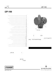
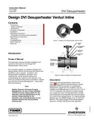
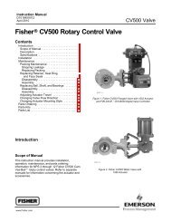
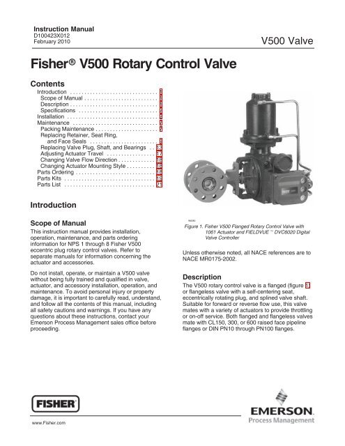
Instruction ManualD100423X012February 2010<strong>V500</strong> <strong>Valve</strong><strong>Fisher</strong> <strong>V500</strong> <strong>Rotary</strong> <strong>Control</strong> <strong>Valve</strong>ContentsIntroduction . . . . . . . . . . . . . . . . . . . . . . . . . . . . . . . 1Scope of Manual . . . . . . . . . . . . . . . . . . . . . . . . . . 1Description . . . . . . . . . . . . . . . . . . . . . . . . . . . . . . . 1Specifications . . . . . . . . . . . . . . . . . . . . . . . . . . . . 2Installation . . . . . . . . . . . . . . . . . . . . . . . . . . . . . . . . 2Maintenance . . . . . . . . . . . . . . . . . . . . . . . . . . . . . . 7Packing Maintenance . . . . . . . . . . . . . . . . . . . . . . 7Replacing Retainer, Seat Ring,and Face Seals . . . . . . . . . . . . . . . . . . . . . . . . 9Replacing <strong>Valve</strong> Plug, Shaft, and Bearings . . 13Adjusting Actuator Travel . . . . . . . . . . . . . . . . . 17Changing <strong>Valve</strong> Flow Direction . . . . . . . . . . . . . 18Changing Actuator Mounting Style . . . . . . . . . . 18Parts Ordering . . . . . . . . . . . . . . . . . . . . . . . . . . . . 18Parts Kits . . . . . . . . . . . . . . . . . . . . . . . . . . . . . . . . 19Parts List . . . . . . . . . . . . . . . . . . . . . . . . . . . . . . . . 21IntroductionScope of ManualThis instruction manual provides installation,operation, maintenance, and parts orderinginformation for NPS 1 through 8 <strong>Fisher</strong> <strong>V500</strong>eccentric plug rotary control valves. Refer toseparate manuals for information concerning theactuator and accessories.Do not install, operate, or maintain a <strong>V500</strong> valvewithout being fully trained and qualified in valve,actuator, and accessory installation, operation, andmaintenance. To avoid personal injury or propertydamage, it is important to carefully read, understand,and follow all the contents of this manual, includingall safety cautions and warnings. If you have anyquestions about these instructions, contact yourEmerson Process Management sales office beforeproceeding.W8380Figure 1. <strong>Fisher</strong> <strong>V500</strong> Flanged <strong>Rotary</strong> <strong>Control</strong> <strong>Valve</strong> with1061 Actuator and FIELDVUE DVC6020 Digital<strong>Valve</strong> <strong>Control</strong>lerUnless otherwise noted, all NACE references are toNACE MR0175-2002.DescriptionThe <strong>V500</strong> rotary control valve is a flanged (figure 1)or flangeless valve with a self-centering seat,eccentrically rotating plug, and splined valve shaft.Suitable for forward or reverse flow use, this valvemates with a variety of actuators to provide throttlingor on-off service. Both flanged and flangeless valvesmate with CL150, 300, or 600 raised face pipelineflanges or DIN PN10 through PN100 flanges.www.<strong>Fisher</strong>.com
<strong>V500</strong> <strong>Valve</strong>Instruction ManualFebruary 2010Table 1. Specifications<strong>Valve</strong> Sizes (1)NPS 1, 11/2, 2, 3, 4, 6, and 8.DN 25, 40, 50, 80, 100, 150 and 200 sizes arealso available.End Connection Style Raised-face flanges, ring-type joint flanges(ASME B16.5), or flangeless valve bodydesigned to fit between raised face flanges. CL150, CL300, or CL600; (CL600 is notavailable in NPS 6 and 8 flangeless valve bodies).DIN PN10 through PN100 flanges also available;consult your Emerson Process Managementsales officeMaximum Inlet Pressure (2)Consistent with applicable ASME or DIN flangeratings standardsShutoff ClassificationClass IV per ANSI/FCI 70-2 and IEC 60534-4(0.01% of valve capacity at full travel), for eitherflow direction. Leak rates for full and restrictedport valves are based on full port capacities.Reduced port valves seat at the full port diameter.Flow Direction Reverse Flow (Standard Direction): Pastvalve plug and through seat ring tends to closethe valve, recommended for erosive and generalservice Forward Flow: Through seat ring andpast valve plug; tends to open the valve,recommended for high pressure drop and highcycle serviceActuator Mounting Left-hand or right-hand as viewed from theupstream side of the valve. See figure 2<strong>Valve</strong> Plug RotationCounterclockwise to close (when viewed fromactuator side of valve) through 90 degrees ofvalve plug rotation<strong>Valve</strong>/Actuator ActionWith diaphragm or piston rotary actuator,field-reversible between push-down-to-close(extending actuator rod closes the valve) and push-down-to-open (extending actuator rodopens the valve)Flow CharacteristicModified linear1. The <strong>Valve</strong> Size shown in this manual refers to Nominal Pipe Size (NPS).2. The pressure or temperature limits in this manual and any applicable standard limitations should not be exceeded.3. Shaft diameter and spline end must match available shaft diameter of actuator.Shaft Diameters (3) and Approximate WeightsSee table 2InstallationWARNINGAlways wear protective gloves,clothing, and eyewear whenperforming any maintenanceoperations to avoid personal injury.To avoid personal injury or propertydamage resulting from the suddenrelease of pressure, do not install thevalve assembly where serviceconditions could exceed the limitsgiven on the appropriate nameplates,or the mating pipe flange rating. Usepressure-relieving devices as requiredby government or accepted industrycodes and good engineering practices.Check with your process or safetyengineer for any other hazards thatmay be present from exposure toprocess media.If installing into an existingapplication, also refer to the WARNINGat the beginning of the Maintenancesection in this instruction manual.CAUTIONWhen ordered, the valve configurationand construction materials wereselected to meet particular pressure,2
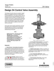
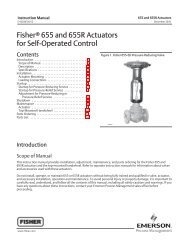
Instruction ManualFebruary 2010<strong>V500</strong> <strong>Valve</strong>VALVE SIZE,NPSSHAFT DIAMETERThrough<strong>Valve</strong>At SplineEndTable 2. Shaft Diameter and Approximate WeightsFlangedAPPROXIMATE WEIGHTFlangelessCL150 CL300 CL600 CL150 CL300 CL600mm kg kg1 12.7 12.7 5.4 5.9 5.9 3.6 3.6 3.611/2 15.9 15.9 8.6 9.5 10 5.4 5.4 5.42 15.9 15.9 9.5 11 13 8.2 8.2 8.2325.4 25.425.4 19.119 24 26 16 16 164 31.8 31.8 36 42 50 34 34 34638.1 38.138.1 31.854 69 93 50 50 8 38.1 38.1 79 98 135 57 68 Inches lbs lbs1 1/2 1/2 12 13 13 8 8 811/2 5/8 5/8 19 21 23 12 12 122 5/8 5/8 21 25 28 18 18 1831 11 3/442 52 57 35 35 354 1-1/4 1-1/4 79 93 111 75 75 7561-1/2 1-1/21-1/2 1-1/4120 152 204 110 110 8 1-1/2 1-1/2 75 217 298 125 150 temperature, pressure drop, andcontrolled fluid conditions.Responsibility for the safety ofprocess media and compatibility ofvalve materials with process mediarests solely with the purchaser andend-user. Since some valve body/trimmaterial combinations are limited intheir pressure drop and temperatureranges, do not apply any otherconditions to the valve without firstcontacting your Emerson ProcessManagement sales office.Key numbers in this procedure are shown infigure 11 (NPS 1 and 11/2 valves) or figure 13(NPS 2 through 8 valves) unless otherwiseindicated.CAUTIONTo prevent product damage duringstorage, keep the valve body cavity dryand clear of foreign material.1. If the valve is to be stored before installation,protect the flange mating surfaces and keep thevalve body cavity dry and clear of foreign material.2. Install a three-valve bypass around the controlvalve assembly if continuous operation will benecessary during inspection and maintenance of thevalve.3. A <strong>V500</strong> valve is normally shipped as part of acontrol valve assembly, with a power or manualactuator mounted on the valve. If the valve andactuator have been purchased separately or if theactuator has been removed from the valve, mountthe actuator according to the Actuator Mountingprocedure. Also, adjust the actuator travel using theAdjusting Actuator Travel procedure before installingthe valve. The necessary measurements cannot bemade with the valve installed.4. Before starting the actual installation of the valve,determine the proper installation orientation of thevalve plug (key 2) and actuator. Determine the flowdirection of the process fluid through the valve. Seefigure 2.NoteFor best shutoff performance and toreduce bearing wear, it isrecommended that you install thevalve shaft in a horizontal direction.See figure 1.3
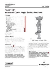
<strong>V500</strong> <strong>Valve</strong>Instruction ManualFebruary 201043A5323-DC0586-1 / ILFigure 2. Index Marks for Actuator Lever Orientation4
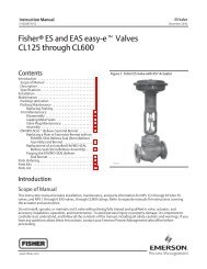
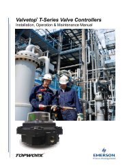
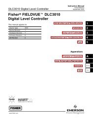
Instruction ManualFebruary 2010<strong>V500</strong> <strong>Valve</strong>Table 3. Line Stud (Key 36)M (1)<strong>Valve</strong> SizeBolt LengthPressure Rating Qty Bolt SizeNPSInchesCL150 4 5/811 UNC 10.623CL300 6 3/410 UNC 11.12CL600 6 3/410 UNC 11.50CL150 6 5/811 UNC 11.444CL300 6 3/410 UNC 12.12CL600 6 7/8 9 UNC 13.626CL150 5 3/410 UNC 13.62CL300 6 3/410 UNC 14.388CL150 8 3/410 UNC 13.62CL300 10 7/8 9 UNC 15.381. These bolts may be installed from either end of the valve.<strong>Valve</strong> SizeNPS681. Use instead of cap screws.Table 4. Line Stud (Key 36) (1)RPressure Rating Qty Bolt SizeBolt LengthInchesCL150 6 3/410 UNC 5.00CL300 6 3/410 UNC 5.00CL150 CL300 4 7/8 9 UNC 5.62Table 5. Cap Screw (Key 37)NP<strong>Valve</strong> SizeBolt Length Overall LengthPressure Rating Qty Bolt SizeNPS Inches InchesCL150 3CL300 4 3/410 UNC 2.38 2.88CL600 4 3/410 UNC 2.38 2.88CL150 4 5/811 UNC 2.00 2.444CL300 4 3/410 UNC 2.38 2.88CL600 4 7/8 9 UNC 2.75 3.38MLINESTUDS1LINE STUDSCAPSCREWSRNOTE:1 USED INSTEAD OF CAP SCREWSNPA4347/ILFigure 3. Line Bolt Dimensions for Flangeless <strong>Valve</strong> Bodies (also see tables 3, 4 and 5)5
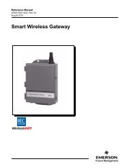
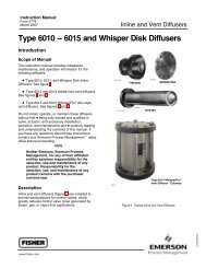
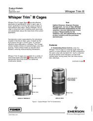
<strong>V500</strong> <strong>Valve</strong>Instruction ManualFebruary 2010VALVE BODYACTUATORAWARNING37A6528-AA3143-2/ILVIEW A-AFigure 4. Optional Shaft-to-Body Bonding Strap Assembly5. Before installing the valve, make sure the flowdirection arrow (key 32) on the valve matches theactual process fluid flow direction through the valvefor the application where the valve will be installed.6. Install the flange gaskets and insert the valvebetween the mating pipeline flanges. For flangelessvalve bodies, also make sure the mating line flangesare aligned. Use flat sheet gaskets compatible withthe process media, or spiral wound gaskets withcompression-controlling center rings.Ceramic TrimSome types of ceramic trim, including the VTC (verytough ceramic) variety, can create a spark undercertain circumstances. When the edge of a ceramicpart is struck against a second ceramic part withenough force, a spark can be created.WARNINGAvoid personal injury and propertydamage from ignition of process fluidcaused by sparks from ceramic trim.Do not use ceramic trim where theprocess fluid is unstable or if it is anexplosive mixture (such as air andether).AThe valve drive shaft is not necessarilygrounded to the pipeline wheninstalled. Personal injury or propertydamage could result if the processfluid or the atmosphere around thevalve is flammable, from an explosioncaused by a discharge of staticelectricity from the valve components.If the valve is installed in a hazardousarea, electrically bond the drive shaftto the valve.1. Prepare to install the line bolts and nuts. Forflangeless valves, consult figure 3 before installingthe line bolts and nuts. Figure 3 shows the line boltclearances required when installing flangelessvalves.NoteStandard PTFE packing is composedof a partially conductive carbon-filledPTFE female adaptor with PTFE V-ringpacking. Standard graphite packing iscomposed of all conductive graphiteribbon packing rings. Alternateshaft-to-valve body bonding isavailable for hazardous service areaswhere the standard packing is notsufficient to bond the shaft to thevalve (see the following step).2. For hazardous applications, attach the bondingstrap assembly (key 131) to the shaft with the clamp(key 130) and connect the other end of bondingstrap assembly to the valve body with the cap screw(key 25). See figure 4.For all valve bodies, install the line bolts and nuts;then, tighten them using accepted boltingprocedures. These procedures include, but are notlimited to, lubricating the line bolts and hex nuts andtightening the nuts in a crisscross sequence toensure proper gasket load.3. If a purge is desired for the purged bearingconstruction, remove the pipe plugs (keys 29and 24) and install the purge lines. Purge pressureshould be greater than the pressure within the valveand the purge fluid should be as clean as possible.4. Connect pressure lines to the actuator asindicated in the actuator instruction manual. When amanual actuator is used with a power actuator,6
Instruction ManualFebruary 2010<strong>V500</strong> <strong>Valve</strong>install a bypass valve on the power actuator (if notalready supplied) for use during manual operation.WARNINGPersonal injury could result frompacking leakage. <strong>Valve</strong> packing wastightened before shipment; however,the packing might require somereadjustment to meet specific serviceconditions. Check with your processor safety engineer for any otherhazards that may be present fromexposure to process media.If the valve has ENVIRO-SEAL live-loaded packinginstalled readjustment will probably not be required.See the Emerson Process Management instructionmanual entitled ENVIRO-SEAL Packing System for<strong>Rotary</strong> <strong>Valve</strong>s, D101643X012 for packinginstructions. If you wish to convert your presentpacking arrangement to ENVIRO-SEAL packing,refer to the retrofit kits listed in the Parts Kit sectionlater in this manual.MaintenanceWARNINGAvoid personal injury or propertydamage from sudden release ofprocess pressure or bursting of parts.Before performing any maintenanceoperations: Do not remove the actuator fromthe valve while the valve is stillpressurized. Always wear protective gloves,clothing and eyewear when performingany maintenance operations to avoidpersonal injury. Disconnect any operating linesproviding air pressure, electric power,or a control signal to the actuator. Besure the actuator cannot suddenlyopen or close the valve. Use bypass valves or completelyshut off the process to isolate thevalve from process pressure. Relieveprocess pressure from both sides ofthe valve. Drain the process mediafrom both sides of the valve. Vent the power actuator loadingpressure and relieve any actuatorspring precompression. Use lock-out procedures to besure that the above measures stay ineffect while you work on theequipment. The valve packing area maycontain process fluids that arepressurized, even when the valve hasbeen removed from the pipeline.Process fluids may spray out underpressure when removing the packinghardware or packing rings. Check with your process or safetyengineer for any other hazards thatmay be present from exposure toprocess media.<strong>Valve</strong> parts are subject to normal wear and must beinspected and replaced as necessary. Thefrequency of inspection and replacement dependsupon the severity of service conditions.As used in these instructions, the term ‘‘actuator’’refers to power actuators (such as pneumaticdiaphragm or piston actuators) or manual actuators(such as handwheel or handlever actuators).Packing MaintenanceKey numbers are referenced in figures 11 and 13unless otherwise indicated.NoteFor the ENVIRO-SEAL packing system,refer to the Parts Ordering section forretrofit kits and parts kits(see figure14). Refer to the separateENVIRO-SEAL instruction manual formaintenance instructions.Standard ENVIRO-SEAL packingsystems can be used in vacuumservice with packing rings in thestandard orientation. It is notnecessary to reverse theENVIRO-SEAL PTFE packing rings.Stopping LeakageAll maintenance procedures in this section may beperformed with the valve body (key 1) in the line.7
<strong>V500</strong> <strong>Valve</strong>Instruction ManualFebruary 2010For packing other than spring-loaded packings,leakage around the packing follower (key 14) can bestopped by tightening the packing flange nuts(key 16). If leakage cannot be stopped in thismanner, replace the packing according to theReplacing Packing procedure.If the packing is relatively new and tight on the valveshaft (key 3), and if tightening the packing nuts doesnot stop leakage, it is possible that the valve shaft isworn or nicked so that a seal cannot be made. If theleakage comes from the outside diameter of thepacking, it is possible that the leakage is caused bynicks or scratches on the packing box wall. Inspectthe shaft and packing box wall for nicks or scratcheswhen performing the following procedures.Replacing PackingNoteIf the valve has ENVIRO-SEALlive-loaded packing installed, see theseparate ENVIRO-SEAL instructionmanual.This procedure may be performed without removingthe actuator from the valve body if addingPTFE/composition packing rings as a temporarymeasure. However, the actuator must be removed ifreplacing any other kind of packing or if the metalpacking parts (keys 14, 17, and, if used, 18) need tobe replaced.Removing the Packing1. Isolate the control valve from the line pressure,release pressure from both sides of the valve, anddrain the process media from both sides of thevalve. If using a power actuator, also shut off allpressure lines to the power actuator, release allpressure from the actuator. Use lock-out proceduresto be sure that the above measures stay in effectwhile you work on the equipment.CAUTIONWhen the actuator is removed from thevalve, do not use a hammer or similartool to drive the lever or actuator offthe valve shaft. Driving the lever oractuator off the valve shaft coulddamage the valve plug, seal, and valve.If necessary, use a wheel puller toremove the lever or actuator from thevalve shaft. It is okay to tap the wheelpuller screw lightly to loosen the leveror actuator, but hitting the screw withexcessive force could damage thevalve plug, seal, and valve.2. If necessary, remove the cap screws (key 25)and hex nuts (key 26). Then remove the actuatorwhile referring to the actuator manual for assistance.3. Remove the packing nuts (key 16) and packingfollower (key 14).4. Remove the old packing rings (key 13), packingbox ring (key 17), and, if used, the lantern ring(key 18).CAUTIONDo not scratch the valve shaft orpacking box wall. Scratching thesesurfaces could cause leakage.5. Clean all accessible metal parts and surfaces toremove particles that would prevent the packingfrom sealing.6. If necessary, complete the steps in the Replacingthe <strong>Valve</strong> Plug, Shaft, and Bearings section, andreturn to the Installing Packing steps below.Installing Packing1. Install the new packing rings and packing boxring by stacking the parts as shown in figure 5. Makesure split rings are arranged so that the splits do notline up to form a leak path. Then slide the stack intothe packing box as far as will go while being carefulto avoid trapping air among the rings.2. Install the studs, packing follower, and nuts.CAUTIONTo prevent possible product damageor leakage, make sure the valve plugremains in the closed position wheninstalling new packing parts.3. Make sure the valve plug is in the closed positionwhen installing new packing parts.4. Insert a screw driver, pry bar, or similar toolbetween the lower ear of the plug and the valvebody (see figure 6). Use the pry to move the plugtightly against the thrust washer and bearing on theactuator side of the valve. Keep the valve plug inthat position until you have completed the packinginstallation.5. Tighten packing flange nuts enough to stopleakage under normal conditions.8
Instruction ManualFebruary 2010<strong>V500</strong> <strong>Valve</strong>6. Mount the actuator while referring to the actuatormounting procedures of the actuator instructionmanual. You must complete the Adjusting ActuatorTravel procedure in this manual before installing thevalve in the pipeline, due to the measurements thatmust be made during the actuator adjustmentprocess.7. When the control valve is being put back intooperation, check the packing follower for leakage,and retighten the packing nuts as necessary.Replacing Retainer, Seat Ring, andFace SealsThis procedure is to be performed if the control valveis not shutting off properly, if the port diameter is tobe changed by installing a different seat ring, or ifseat ring inspection is necessary. The actuator andvalve (key 1) must be removed from the pipeline;however, the actuator may remain mounted duringthis procedure.A retainer tool is required to remove the retainer(key 5), seat ring (key 4), and face seals (key 8). Ifspecifically ordered, a tool is supplied with the valve;a tool can also be ordered individually. If desired, atool can be machined using the dimensions shown infigure 7.During assembly, handle the retainer, seat ring, andface seals carefully. Critical areas that must beprotected are the threads and inner surface of theretainer (key 5), the sealing surfaces of the faceseals (key 8), the face seal grooves in the seat ring(key 4), the shutoff surface of the seat ring, and theface seal surface in the valve body (key 1).A new retainer gasket (key 11) is required wheneverthe retainer (key 5) is removed. Other parts in goodcondition can be reused.Disassembly of Retainer, Seat Ring, andFace SealsKey numbers are shown in figures 11 and 13 unlessotherwise noted.1. Isolate the control valve from the line pressure,release pressure from both sides of the valve body,and drain the process media from both sides of thevalve. If using a power actuator, also shut off allpressure lines to the power actuator, release allpressure from the actuator. Use lock-out proceduresto be sure that the above measures stay in effectwhile you work on the equipment.2. Remove line bolting. Then, remove the controlvalve from the pipeline and place the valve on a flatsurface with the retainer (key 5) facing up.3. Rotate the valve shaft (key 3) to move the valveplug (key 2) into the open position.NoteThe retainer (key 5) was installed atthe factory using the torque listed infigure 8.4. Remove the retainer by engaging the retainertool, attaching an impact wrench or other suitabletool, and unscrewing the retainer. Inspect theretainer.CAUTIONPlace the retainer on a protected, flatsurface where the threads and innersurface will not be contaminated ordamaged.5. Remove the retainer gasket (key 11). Inspect thegasket surfaces on the valve body (key 1).6. Lift out the seat ring (key 4) and both face seals(key 8). Inspect the parts and place them on a flat,protected surface.7. Inspect the shutoff surface of the valve plug. If itis worn, nicked, or scratched, proceed to theReplacing <strong>Valve</strong> Plug, Shaft, and Bearingsprocedure. If the parts are in good shape and do notrequire maintenance, continue to the Assemblyprocedure.Assembly of Retainer, Seat Ring, andFace SealsWARNINGSeat ring installation requires that thevalve plug (key 2) remain in the openposition.To avoid personal injury or damage totools, valve parts, or other itemsresulting from plug closing, preventplug travel by using travel stops,manual actuators, constant supplypressure to a pneumatic actuator, orother steps as appropriate. Wheninstalling the seat ring, keep hands,tools, and other objects out of thevalve.9
<strong>V500</strong> <strong>Valve</strong>Instruction ManualFebruary 2010C0587-5 / ILFigure 5. Packing Arrangements10
Instruction ManualFebruary 2010<strong>V500</strong> <strong>Valve</strong>C0774-1 / ILPTFE/COMPOSITION OR GRAPHITE ENVIRO‐SEAL PACKING ARRANGEMENTSFigure 5. Packing Arrangements (continued)PRY IN THISDIRECTIONTHRUSTWASHERACTUATORSIDE OFVALVENOTE:1. VALVE PLUG SHOULD BE IN THE OPEN POSITIONWHEN TIGHTENING THE PACKING FLANGE NUTS (KEY16).49A3685-DA7073 / ILFigure 6. Pry Bar UseVALVEPLUG1. Apply enough supply pressure to the actuator toopen the valve plug, or take other steps to hold thevalve plug open.2. Clean the valve body, the retainer threads, theretainer gasket surface, and the seat ring sealingsurface.3. Using either face seals (key 8) in good conditionor new face seals, place one seal in the seat ringcavity.11
<strong>V500</strong> <strong>Valve</strong>Instruction ManualFebruary 2010VALVESIZE, NPSA B C DE(HEX)mmTable 6. Data for Making Retainer ToolFGH(SQUARE)A B C D1 26.9 28.4 9.7 6.4 28.4 1.5 4.8 - - - 1.06 1.12 .38 .25 1.12 .06 .19 - - -11/2 (1) 36.6 28.4 9.7 6.4 38.1 3.0 4.8 - - - 1.44 1.12 .38 .25 1.50 .12 .19 - - -11/2 (2) 36.6 19.1 - - - 6.4 - - - 22.4 4.8 12.7 1.44 .75 - - - .25 - - - .88 .19 .502 55.6 19.1 - - - 6.4 - - - 22.4 4.8 12.7 2.19 .75 - - - .25 - - - .88 .19 .503 79.2 33.3 - - - 7.9 - - - 41.4 7.9 19.0 3.12 1.31 - - - .31 - - - 1.62 .31 .75E(HEX)InchesFGH(SQUARE)4 104.6 33.3 - - - 7.9 - - - 41.4 7.9 25.4 4.12 1.31 - - - .31 - - - 1.62 .31 1.006 155.4 38.1 - - - 11.2 - - - 63.5 11.2 25.4 6.12 1.50 - - - .44 - - - 2.50 .44 1.008 203.2 50.8 - - - 11.2 - - - 101.6 11.2 38.1 8.00 2.00 - - - .44 - - - 4.00 .44 1.501. Dimensions for 11/2 inch tool made from hex barstock, an optional material.2. Dimensions for 11/2 inch tool made from round barstock.Table 7. Retainer TorqueRETAINER TORQUEVALVE SIZE, NPSNmLbfft1 140 10011/2 185 1352 260 1903 515 3804 1170 8606 2305 17008 3120 2300RETAINER TOOL FORNPS 1 VALVE(OPTIONAL FOR NPS 11/2 VALVE)B1899-2 / ILRETAINER TOOL FOR NPS 11/2THROUGH 8 VALVESFigure 7. Data for Making and Using Retainer Tool (Key 33) (also see tables 6 and 7)12
Instruction ManualFebruary 2010<strong>V500</strong> <strong>Valve</strong>VALVE SIZETable 8. Assembly ClearanceSEAT RING AND RETAINER CLEARANCEmmInchesNPS Min Max Min Max2 0.05 0.17 0.002 0.0073, 4, 6, and 8 0.08 0.30 0.003 0.012NoteThe seat ring (key 4) may have one ortwo shutoff surfaces. The shutoffsurfaces are the narrow, roundededges of the seat ring bore. Inspect theseat ring and locate the shutoffsurfaces before proceeding.4. Insert the seat ring into the seat ring cavity withthe correct shutoff surface facing the valve plug andshaft. The seat ring will cover the face seal installedin step 3.5. Place the second face seal on the seat ring.6. Apply anti-seize lubricant to the gasket surface inthe valve body. Install the gasket (key 11), whilemaking certain that for NPS 2 through 8 sizes theconcave surface of the gasket is up (hump surfaceof gasket down).7. Apply anti-seize lubricant to the threads andbottom of the retainer (key 5). Thread the retainerinto the valve body.8. Refer to figure 7. With the appropriate torqueindicating tool, tighten the retainer to the torquelisted in table 7.9. A gap between the seat ring (key 4) and retainer(key 5) allows the seat ring to self-center. Applyingthe proper amount of torque during installationshould position the retainer and seat ring properly.However, for NPS 2 through 8 valves, use a feelergauge to measure between the parts as shown infigure 13, making certain the necessary clearanceexists. Compare the measured gap to the clearancein table 8 and proceed as follows: If the measured clearance is within tablevalues, proceed to the next step. If the measured gap is larger than themaximum, tighten the retainer—apply more torquethan that listed in table 7, if necessary—until theclearance is within maximum and minimum values. If the measured clearance is smaller than theminimum, remove the retainer, seat ring, and faceseals, clean the parts, and reassemble so as toobtain the necessary clearance.10. Perform the Adjusting Actuator Travel procedureand then install the control valve in the pipeline.Replacing <strong>Valve</strong> Plug, Shaft, andBearingsPerform this procedure to replace the valve plug(key 2), expansion pin assembly (keys 9 and 10),shaft (key 3), or bearings (key 6). These parts areindependently replaceable; for example, installing anew valve plug does not require replacing a reusablevalve shaft or expansion pin assembly. Key numbersrefer to figures 11 and 13 unless otherwiseindicated.Disassembly of <strong>Valve</strong> Plug, Shaft, andBearingsWARNINGTo avoid personal injury resulting fromcontact with edges of the valve plug(key 2) and seat ring (key 4) duringplug rotation, stay clear of the plugedges when rotating the plug. To avoiddamage to tools, valve parts, or otheritems resulting from valve plugrotation, keep tools and other propertyaway from the edges of the plug.CAUTIONTo avoid increased leakage, increasedvalve component wear or possibledamage to the valve body (key 1), plug(key 2), shaft (key 3), and bearings (key6) resulting from a sharp blow to theactuator body or valve parts, use awheel puller to separate the actuatorparts from the valve shaft.Do not drive the actuator parts off thevalve shaft since this could move thevalve bearings, shaft, and plug awayfrom proper alignment, causingimproper seating of the plug. Suchmisalignment may result in damage tovalve components if the valve isreturned to service withoutdisassembly and inspection of thevalve plug alignment.13
<strong>V500</strong> <strong>Valve</strong>Instruction ManualFebruary 2010VALVESIZE,NPSTable 9. Data for Tapped Hole in <strong>Valve</strong> ShaftSHAFT DIAMETERSThrough<strong>Valve</strong>BodyAt SplineEndThrough<strong>Valve</strong>BodyAt SplineEndTHREADSIZE,UNCmm mm Inches1 12.7 12.7 0.50 0.50 10-2411/2 15.9 15.9 0.62 0.62 1/4-202 15.9 12.7 0.62 0.62 10-24325.4 15.9 1.00 1.00 3/8-1625.4 25.4 1.00 0.75 5/16-184 31.8 19.1 1.25 1.25 3/8-16638.1 38.1 1.50 1.50 1/2-1338.1 31.8 1.50 1.25 3/8-168 38.1 38.1 1.50 1.50 1/2-13A3307-1 / ILFigure 8. Detail of <strong>Valve</strong> Plug for Pin RemovalNoteFollowing removal of the valve fromthe pipeline and partial disassembly,the valve shaft may be used to removebearings in accordance with theprocedure described in step 8, below.1. Isolate the control valve from the line pressure,release pressure from both sides of the valve body,and drain the process media from both sides of thevalve. If using a power actuator, also shut off allpressure lines to the power actuator, release allpressure from the actuator. Use lock-out proceduresto be sure that the above measures stay in effectwhile you work on the equipment.2. Remove the actuator cover. Note the actuatororientation with respect to the valve body and thelever orientation with respect to the valve drive shaft(see figure 2). Remove the lever but do not loosenthe actuator turnbuckle adjustment. Remove theactuator mounting screws and nuts, and remove theactuator. If necessary, refer to the actuatorinstruction manual for assistance.3. With the valve body (key 1) out of the pipeline,loosen the packing nuts (key 16). If the packing is tobe reused, do not remove it. However, EmersonProcess Management recommends that the packingbe replaced whenever the drive shaft is removed.4. Rotate the plug (key 2) to the fully open position.5. Refer to figure 8. Find the expansion pin (key 9)and the taper pin (key 10) inside of it. These partsare holding the valve plug in position on the shaft.Find the larger hole in the valve plug hub wherethese pins enter the hub. On the opposite side of theplug hub is a smaller hole where the chamfered endof the expansion pin rests on the inner lip of thehole. Using a pin punch and hammer, strike thechamfered end of the expansion pin through thesmaller hole. Remove both pins from the valve plughub in the direction shown in figure 8.Driving the pins in the other direction will tighten thepins.WARNINGTo avoid personal injury or damage totools, valve parts, or other items andplug damage resulting from the valveplug falling from the valve body,support the plug to prevent it fromfalling as the shaft (key 3) is beingremoved.6. Pull the shaft (key 3) from the valve body. If theshaft cannot be removed by hand, attach a slidehammer or similar tool to the spline end of the valveshaft. Each shaft, on the NPS 6 and 8 sizes, has atapped hole at the spline end of the shaft; refer totable 9 for thread sizes.7. Remove the plug and thrust washer (key 12) fromthe valve body.NoteTwo shaft bearings (key 6) are locatedinside the valve body on either side ofthe valve plug. Only one of these twobearings is identified by key 6. The14
Instruction ManualFebruary 2010<strong>V500</strong> <strong>Valve</strong>other bearing is located along thevalve shaft on the other side of thevalve plug.8. If the shaft bearings are to be replaced, removethe packing (key 13).9. If the bearing closest to the packing requiresreplacement and cannot be removed by hand, pressit out using a ram with dimensions given in figure 9and table 10.CAUTIONEnsure the bearing stop is not movedwhen pressing out the bearing.Movement may cause the new bearingand valve plug to not be centered withthe seal, causing possible leakage ordamage of the seal/plug.VALVESIZE, NPS111/223468A3308 / ILTable 10. Ram DimensionsA MAXIMUMLMINIMUMmm Inches mm Inches15.114.718.317.918.317.927.827.434.133.742.141.742.141.7.594.578.719.703.719.7031.0941.0781.3441.3281.6561.6411.6561.641114 4.50114 4.50127 5.00127 6.50165 6.50197 7.75129 9.00Insert the ram through the packing box and pressthe bearing into the valve body cavity. The bearingstop (key 7) does not need to be removed; take carenot to move the bearing stop when pressing out thebearing.10. If the second bearing (key 6) requiresreplacement and cannot be removed by hand, useone of the following methods: Knock or pry the bearing out, or Use the valve shaft as a piston to drive thebearing from the valve body. To accomplish this,first, fill the bearing bore with a heavy grease andthen insert the end of the shaft back through thevalve body and into the grease-filled bearing. Protectthe splined end of the shaft with, for example, ablock of wood; then strike the protected end. Whenthe shaft is struck, it will act as a piston, pushing thegrease into the bearing bore. The grease will thenforce the bearing out of the bore and farther alongthe shaft. Soon, the bearing will be positioned foreasy removal.11. If used, remove the O-rings (keys 19 and 20)from the bearings. Also, remove the pipe plug(key 29).Figure 9. Ram Dimension for Bearing Removal (also seetable 10)Assembly of <strong>Valve</strong> Plug, Shaft, andBearingsNoteBefore starting to assemble the valvecomponents, place the valve body(key 1) on a flat surface with theretainer (key 5) facing down as shownin figure 10. This orientation of thevalve body allows easier installation ofthe valve plug.1. Thoroughly clean the parts before assembly.2. If O-rings (keys 19 and 20) are used, apply asmall amount of lubricant to the O-rings so thebearings will easily slide into the valve body. Insertthe smaller O-ring (key 20) inside the bearing andthe larger O-ring (key 19) around the outside of thebearing.CAUTIONTo avoid damage to O-rings resultingfrom contact with sharp edges withinthe bearing holes, use appropriatecare when installing the O-rings.15
<strong>V500</strong> <strong>Valve</strong>Instruction ManualFebruary 20103. Slide the bearings (key 6) and O-rings (keys 19and 20), if used, into the valve body as shown infigures 13 and 12.NotePlace the valve body on a flat surfacewith the retainer (key 5) facing downso that you can look into the valvebody cavity. This orientation makesinstalling the valve plug easier.4. Inspect the valve shaft (key 3). Insert the shaftend opposite the splined end into the packing boxand through the set of bearings installed in thepacking box in step 3. Stop before the shaft entersthe main valve body cavity. Support the splined endof the shaft.5. Determine the correct orientation of the valveplug (key 2) required by the specific installationorientation of the valve and the flow direction of theprocess fluid. See figure 2.6. Inspect the valve plug. Note the location of thelarger hole on the valve plug hub. Place the valveplug in the valve body cavity.7. Position the valve plug so that the larger hole isfacing up, away from the seat ring and retainer. Thevalve plug must also be oriented so that the seatingsurface of the plug is correctly positioned for thespecific application as shown by the illustrations infigure 2.NoteBefore proceeding, inspect the valveplug position once again to ensure thecorrect orientation as described instep 6. If the valve plug is not properlyinstalled, it will not rotate properly andwill not shutoff in service.8. Hold the thrust washer(s) (key 12) between thevalve plug (key 2) and the bearing installed next tothe packing as shown in figures 11 and 13. Thenslide the valve shaft (key 3) from the packing boxinto the valve body through the thrust washer(s) andplug. If the shaft material is S17400, use two 0.7938mm (1/32 inch) 17-7 PH thrust washers. If the shaftA3309-1 / ILFigure 10. Detail of <strong>Valve</strong> Plug for Pin Insertionmaterial is S20910, use one 1.587 mm (1/16 inch)alloy 6 thrust washer.9. Secure the valve plug in the correct openposition. Inspect the splined end of the valve shaftand locate the slash mark on the splined end. Rotatethe valve shaft until the slash mark is vertical andfacing out from the center of the shaft in the samedirection as the valve plug seating surface. Seefigure 10.NoteWhen the valve shaft is correctlypositioned, the slash mark on thesplined end will be parallel with theplug shutoff surface. See figure 10.10. Look into the valve body and find the larger pinhole on one side of the valve plug hub. Find thesmaller hole on the opposite side of the hub. Theseholes should line up with the hole through the shaft(key 3).NoteIf the holes in the valve plug hub donot line up with the hole in the shaft,check the slash mark on the splinedend of the shaft. Make sure the shaftand plug are properly oriented.CAUTIONFor NPS 1 through 2, use only N10276expansion and taper pins (keys 9 and10) with VTC (ceramic) valve plug. With16
Instruction ManualFebruary 2010<strong>V500</strong> <strong>Valve</strong>any other pin material, there is dangerof the pins expanding and cracking theplug as temperature rises. For thatreason, the NPS 1 through 2 VTC valveplugs are sold only as a set thatincludes N10276 pins. Use only thepins that are furnished with the set.Components of the VTC valve plug assembly for theNPS 3 through 8 cannot be repaired in the field.11. Place the chamfered end of the expansion pin(key 9) into the larger hole in the plug hub (seefigure 11).CAUTIONTo avoid damage to the expansion pin,valve plug, or shaft resulting from theapplication of excessive force on theexpansion pin, use appropriate carewhen driving the expansion pinthrough the plug hub and shaft. Usethe right tool. Do not use excessiveforce.12. Drive the expansion pin into the larger hole untilthe chamfered end of the pin reaches the inner lip ofthe smaller hole on the opposite side of the plug.Closely observe the progress of the pin to avoidstriking it after it has reached the lip of the smallerhole.13. Place the taper pin (key 10) into the open end ofthe expansion pin. Drive the taper pin into theexpansion pin until the pins, plug, and shaft aresnug. Do not attempt to drive either pin flush with thehub.14. Rotate the plug by hand to check that it rotatesproperly. If rotation interferes with the valve body,drive out the pins (keys 9 and 10), remove the valveshaft (key 3), and repeat this procedure starting withstep 4.15. If used, install the pipe plug (key 29).16. If the seat ring (key 4), face seals (key 8), andretainer (key 5) need to be installed, complete theassembly instructions in the procedure for ReplacingRetainer, Seat Ring, and Face Seals. If the seat ringhas previously been installed, proceed to AdjustingActuator Travel.Adjusting Actuator TravelPerform this procedure whenever the actuator isremoved or disconnected from the valve andwhenever the seat ring and retainer (keys 4 and 5)are removed. Actuator travel that is too short willincrease shutoff leakage; too much travel will causeexcessive plug and seat ring torque.Any of the <strong>Fisher</strong> pneumatic (spring-and- diaphragm,piston, or spring-return piston), electric,electrohydraulic, or manual actuators--or any otheroperator--must be adjusted for use with a <strong>V500</strong>valve so that the valve plug is rotated to the fullyclosed position. The fully closed position is obtainedwhen a gap of 0.001 inch exists between the seatring (key 5) and retainer (key 4).Note that this gap is also measured whenassembling the seat ring, retainer, and face seals toensure correct assembly. Measure the gapaccording to this procedure to ensure properactuator adjustment. Merely completing theassembly measurement is not sufficient.Travel for different actuators is adjusted differently(some use turnbuckle assemblies; some useexternally adjusted travel stops; others use internallimit switches). Refer to the actuator instructionmanual for adjustment instructions.1. Mount the actuator following the instructions inthe actuator instruction manual. Refer to figure 3 toselect actuator mounting style and position and toorient the actuator lever with the valve shaft (key 3).2. For actuators with clamped levers,CAUTIONWhen installing the actuator onto thevalve, do not use a hammer or similartool to drive the lever or actuator ontothe valve shaft. Driving the lever oractuator onto the valve shaft coulddamage the valve plug, seal ring, andother valve components. Clean the valve shaft splines and actuator leversplines to be sure the actuator lever will slide oneasily. Pull the valve shaft (key 3), by hand, toward thepacking (key 13). Or, If the lever does not slide easily on the valveshaft, carefully wedge the valve plug solidly againstthe actuator-side thrust washer using a screwdriveror similar tool in the same direction as the pry barshown in figure 6.3. Clamp the lever to the valve shaft.17
<strong>V500</strong> <strong>Valve</strong>CAUTIONDo not apply full actuator signal(pressure or power) to the actuator inthe next step. Full signal may wedgethe valve plug into the seat ring. Use aregulated signal source and graduallyincrease the signal to slowly stroke theactuator.4. Adjust actuator travel and stroke the actuator sothat the plug is close to but not contacting the seatring at full actuator travel. If available on electricactuators, use a manual handwheel to position theplug.5. Adjust travel, using full actuator signal, until thevalve plug contacts the seat ring around its fullcircumference. This contact self-centers the seatring on the valve plug.6. Continue to adjust travel until a gap of 0.001 inchexists between the seat ring and retainer, as shownin figure 13, at full actuator travel.7. Refer to the actuator instruction manual to lockthe actuator travel adjustment.Changing <strong>Valve</strong> Flow DirectionThe <strong>V500</strong> valve may be installed in either forward orreverse flow service. Forward flow enters the seatring first, then flows past the valve plug. If changingflow direction is necessary, release all pressure fromthe valve and actuator. Remove the control valveassembly from the pipeline and rotate the assemblyabout the valve shaft to put the retainer end of thevalve where the other end was. Refer to theprocedure for Changing Actuator Mounting Style ifthe actuator must be repositioned, and refer to theInstallation section to install the control valveassembly. Be sure to reposition the flow directionarrow on the valve body.Instruction ManualFebruary 2010Changing Actuator Mounting StyleRefer to figure 3 of this manual and the actuatorinstruction manual when changing mounting stylesor positions. Right-hand mounting places theactuator on the right side of the valve as viewed fromthe upstream side of the valve; left-hand mountingplaces the actuator on the left side of the valve.Remember that the upstream side of the valve inletis the retainer end of the valve body for forward flowand the other end of the valve body is the upstreamside for reverse flow.Complete the Adjusting Actuator Travel procedurewhenever the actuator is removed.Parts OrderingA serial number is assigned to each valve andstamped on the nameplate. Always refer to the valveserial number when corresponding with yourEmerson Process Management sales office. Whenordering replacement parts, also specify the partname and desired material.WARNINGUse only genuine <strong>Fisher</strong> replacementparts. Components that are notsupplied by Emerson ProcessManagement should not, under anycircumstances, be used in any <strong>Fisher</strong>valve, because they may void yourwarranty, might adversely affect theperformance of the valve, and couldcause personal injury and propertydamage.NoteNeither Emerson, Emerson ProcessManagement, nor any of their affiliatedentities assumes responsibility for theselection, use, or maintenance of anyproduct. Responsibility for theselection, use, and maintenance of anyproduct remains with the purchaserand end user.18
Instruction ManualFebruary 2010Parts KitsRepair KitsRepair kits include recommended spares forstandard and sealed bearing constructions.Parts Included in KitsKey Number DescriptionQuantity in Kit9 Expansion pin 110 Taper pin 111 Retainer gasket 119 O-ring (sealed bearing only) 220 O-ring (sealed bearing only) 2<strong>Valve</strong> Size NPSKit Parts Number1 R<strong>V500</strong>X0001211/2 R<strong>V500</strong>X000222 R<strong>V500</strong>X000323 R<strong>V500</strong>X000424 R<strong>V500</strong>X000526 R<strong>V500</strong>X000628 R<strong>V500</strong>X00072Repair Kits for ENVIRO-SEAL PackingPacking boxes in these valves may be deep-drilled.If the valve being repaired has a deep packing box,additional parts are required. Refer to the PackingMaintenance section in this manual.<strong>V500</strong> <strong>Valve</strong>Retrofit Kits for ENVIRO-SEAL PackingRetrofit kits include parts to convert existing <strong>V500</strong>valves with single depth packing box to theENVIRO-SEAL packing box construction. Retrofitkits include single PTFE or graphite packing boxconstruction (see following table).Parts included in KitsQuantity in KitKeyNumberDescription PTFE Graphite100 Packing stud 2 2101 Packing nut 2 2102 Packing flange 1 1103 Spring pack assembly 1 1105 Packing set 1 1106 Antiextrusion washer 2 107 Packing box ring 1 1<strong>Valve</strong> Size NPSKit Parts Number1 RRTYXRT001211/2 & 2 RRTYXRT00223 RRTYXRT00524 RRTYXRT00626 & 8 RRTYXRT0072Parts included in KitsQuantity in KitKeyNumberDescription PTFE Graphite105 Packing Set 1 1106 Anti-Extrusion Washer 2 (1)1. Included in packing set, key 105.<strong>Valve</strong> Size NPSKit Parts Number1 RRTYX00001211/2 & 2 RRTYX0000223 RRTYX0000524 RRTYX0000626 & 8 RRTYX000072Table 11. Explanation of <strong>Valve</strong> Construction (1)For These Packing and Bearing ConstructionsUse These <strong>Valve</strong> ConstructionsSingle packing and standard bearingsStandard packing box without end tappingSingle packing and sealed bearingsStandard packing box with end tappingDouble packing and standard bearingsDeep packing box without lube or end tappingLeakoff packing and standard bearingsDeep packing box with only lube tappingDouble packing and sealed bearingsDeep packing box with only lube tappingLeakoff packing and sealed bearingsDeep packing box with both lube and end tappingPurged bearing and single packing for purged bearingsDeep packing box with both lube and end tapping1. Please contact your Emerson Process Management sales office for more information.19
<strong>V500</strong> <strong>Valve</strong>Instruction ManualFebruary 2010OPTIONALPIPE PLUGOPTIONAL APPLY LUBRICANT39A9677-D / DOCFigure 11. <strong>Fisher</strong> <strong>V500</strong> <strong>Rotary</strong> <strong>Control</strong> Flange <strong>Valve</strong>, NPS 1 and 11/220
Instruction ManualFebruary 2010<strong>V500</strong> <strong>Valve</strong>SHUTOFF SURFACEVALVE PLUGSEATING SURFACEHUB24B9722-B / DOCCAP SCREWB2423-1 / ILSTANDARDVALVE PLUG DETAIL(TOP VIEW)ALL SIZESVTC (CERAMIC) VALVE PLUGFOR NPS 3 THROUGH 8CERAMIC TRIM AVAILABLEPRE‐ASSEMBLED ONLYFigure 12. <strong>Valve</strong> Plug ViewsVTC (CERAMIC) VALVE PLUGFOR NPS 1, 1-1/2, AND 2(NPS 1 SHOWN)Parts ListNotePart numbers are shown for recommended sparesonly. For part numbers not shown, contact yourEmerson Process Management sales office.Key Description Part Number<strong>Valve</strong> Common Parts (figures 11 and13)1 <strong>Valve</strong> Body/Bearing AssemblyIf you need a valve body as a replacement part, order by valvesize, serial number, and desired material.2 <strong>Valve</strong> Plug3 <strong>Valve</strong> Shaft4* Seat RingFull Port, Metal seat construction See following table5 Retainer6* Bearing (2 req’d) See following table7 Bearing Stop, S31600 (316 SST)8* Face Seal, (2 req’d)MetalNPS 119A5160X022NPS 11/219A5145X022NPS 219A3747X022NPS 319A3716X022NPS 419A3680X042NPS 619A4243X032NPS 819A3649X022PTFENPS 110B9116X012NPS 11/210B9117X012NPS 210B8275X022NPS 310B9118X012NPS 410B9119X012NPS 610B9120X012NPS 810B9121X012Key Description Part Number9* Expansion Pin, S20910NPS 119A5163X012NPS 11/2 & 219A3750X012NPS 319A3717X012NPS 419A3681X012NPS 6 & 819A3687X01210* Taper Pin, S20910NPS 116A5511X012NPS 11/2 & 219A3749X012NPS 3F14114X0012NPS 416A5515X012NPS 6 & 8H13748K003211* Retainer GasketNPS 1, graphite laminate19A5162X022NPS 11/2, graphite laminate19A5176X022NPS 2, S3160019A5197X012NPS 3, S3160019A5198X012NPS 4, S3160019A5199X012NPS 6, S3160019A5200X012NPS 8, S3160019A6401X01212 Thrust Washer (1)13* Packing SetPTFE & carbon-filled V-ring set (conductive)Single & purged bearing construction - 1 req’dDouble - 2 req’dNPS 112A9016X022NPS 11/2 & 21R5795X0012NPS 312A8832X022NPS 412A8951X022NPS 6 & 812A8935X022PTFE V-ring set (nonconductive)Single & purged bearing construction - 1 req’dDouble - 2 req’dNPS 112A9016X012NPS 11/2 & 21R5795D1012NPS 312A8832X012NPS 412A8951X012NPS 6 & 812A8935X012*Recommended spare parts1. A single quantity of the part number is needed you will receive twothrust washers when you specify 17-7PH.21
<strong>V500</strong> <strong>Valve</strong>Instruction ManualFebruary 2010PIPE PLUGOPTIONALOPTIONAL49A3686-F / DOCFigure 13. <strong>Fisher</strong> <strong>V500</strong> <strong>Rotary</strong> <strong>Control</strong> <strong>Valve</strong>, NPS 2, 3, 4, 6, and 822
Instruction ManualFebruary 2010<strong>V500</strong> <strong>Valve</strong>Key Description Part Number13* Packing Set (continued)PTFE/bound composition ringsSingle & purged bearing constructionConductive - 3 req’d & graphite filament ringNonconductive - 4 req’dDouble or LeakoffConductive - 5 req’d & graphite filament ringNonconductive - 6 req’dNPS 11P3905X0172NPS 11/2 & 21J8225X0142NPS 314A0915X012NPS 414A0916X012NPS 6 & 814A1933X012Graphite filament ring - 1 req’duse with PTFE/bound composition conductive packingNPS 11P3905X0172NPS 11/2 & 21J8225X0182NPS 314A0915X042NPS 414A0916X072NPS 6 & 814A1933X022Graphite ribbon ringsSingle & purged bearing construction - 4 req’dDouble or Leakoff - 6 req’dNPS 112A9134X012NPS 11/2 & 212A9135X012NPS 312A9137X012NPS 412A9138X012NPS 6 & 812A9139X01214 Packing Follower, CF8M (316 SST)15 Packing Flange Stud (2 req’d)16 Packing Flange Nut (2 req’d)17* Packing Box Ring, S31600NPS 116A6082X012NPS 11/2 & 216A6083X012NPS 316A6085X012NPS 416A6086X012NPS 6 & 816A6087X01218 Lantern Ring, S3160019* O-Ring (for sealed bearings; 2 req’d)NitrileNPS 111A8741X052NPS 11/2 & 21F4636X0032NPS 310A3804X012NPS 41W1932X0032NPS 6 & 813A2331X022FluorocarbonNPS 111A8741X012NPS 11/2 & 21N571406382NPS 310A3804X032NPS 41W1932X0032NPS 6 & 813A2331X01220* O-Ring (for sealed bearings; 2 req’d)NitrileNPS 11J4888X0052NPS 11/2 & 211A8741X052NPS 310A8217X042NPS 410A3803X012NPS 6 & 81F1153X0012FluorocarbonNPS 11J4888X0032NPS 11/2 & 211A8741X012NPS 310A8217X012NPS 410A3803X032NPS 6 & 81F1153X0022Key Description Part Number21 Anti-seize lubricant(not furnished with valve)22 Nameplate, SST23 Drive Screw, SST (6 req’d)24 Pipe Plug, S3170024 Isolator/Lubricator <strong>Valve</strong> (not shown)Pipe nipple (not shown)25 Cap Screw26 Hex Nut28* Packing Washer (not shown)Zinc (for graphite/ribbon pkg only)Single - 3 req’dDouble or leakoff - 4 req’dNPS 114A8362X012NPS 11/2 & 214A9771X012NPS 314A8365X012NPS 414A8366X012NPS 6 & 814A8367X01229 Pipe Plug (for sealed or purged bearing constructions) Optional30 Nameplate (not req’d when actuator is furnished)31 Nameplate Wire, steel (not req’d when actuator is furnished)32 Flow Arrow, SST33 Retainer Tool, steel (not shown)36 Line Studs (for flangeless valve bodies) - see following table fornumber required37 Cap Screws (for flangeless valve bodies) - see following tablefor number required130 Clamp SST (req’d w/ nonconductive packing)131 Bonding Strap Assembly (req’d w/nonconductive packing)ENVIRO-SEAL Packing System(figure 14)100 Packing Flange Stud (2 req’d)SA193 B7 zn plNPS 1, 11/2 & 2NPS 3NPS 4NPS 6 & 8SA193 B8MNPS 1, 11/2 & 2NPS 3NPS 4NPS 6 & 8SA193 B7M (NACE MR0175-2002)NPS 1, 11/2 & 2NPS 3NPS 4NPS 6 & 8101 Packing Flange Nut (2 req’d)SA193 2H zn plNPS 1, 11/2 & 2NPS 3NPS 4, 6, & 8SA193 8MNPS 1, 11/2 & 2NPS 3NPS 4, 6, & 8SA193 2HM (NACE MR0175-2002)NPS 1, 11/2 & 2102 Packing Flange, SST103 Spring Pack Assembly105* Packing SetPTFENPS 111B3814X10216A1061X08212A8926X0121P56823103211B3814X10216A1061X02212A8926X0221P56823522211B3814X03216A1061X04212A8926X0321P5682X00621E9440241121A3753241121A3412241121E9440352521A3753352521A3412352521E9440X001212B7053X012*Recommended spare parts23
<strong>V500</strong> <strong>Valve</strong>Instruction ManualFebruary 2010Figure 14. ENVIRO-SEAL <strong>Rotary</strong> Packing Arrangements with PTFE and Graphite Packing.Key Description Part NumberKey Description Part Number105* Packing Set (continued)PTFENPS 11/2 & 2NPS 3NPS 4NPS 6 & 8GraphiteNPS 1NPS 11/2 & 2NPS 3NPS 4NPS 6 & 812B7402X01212B7438X01212B7450X01212B7462X01213B8816X01213B8816X03213B8816X09213B8816X11213B8816X142106* Anti-Extrusion Ring, Composition/graphitefilled PEEK (2 req’d)Single PTFE packing w/std packing boxNPS 1NPS 11/2 & 2NPS 3NPS 4NPS 6 & 8Double PTFE packing w/std & deep pkg boxNPS 1NPS 11/2 & 2NPS 3NPS 412B7504X01212B7406X01212B7442X01212B7454X01212B7466X01212B7504X01212B7406X01212B7442X01212B7454X01224*Recommended spare parts
Instruction ManualFebruary 2010<strong>V500</strong> <strong>Valve</strong>Key Description Part Number107* Packing Box RingSingle PTFE packing w/std packing boxNPS 116A6082X012NPS 11/2 & 216A6083X012NPS 316A6085X012NPS 416A6086X012NPS 6 & 816A6087X012Double PTFE packing w/std packing boxNPS 116A6082X012NPS 11/2 & 216A6083X012NPS 316A6085X012NPS 416A6086X012Double PTFE packing w/deep packing box (2 req’d)NPS 112B7062X012NPS 11/2 & 212B7412X012NPS 312B7448X012NPS 412B7460X012Graphite packing w/std packing boxNPS 116A6082X012NPS 11/2 & 216A6083X012NPS 316A6085X012NPS 416A6086X012NPS 6 & 816A6087X012Key Description Part Number108* Packing RingDouble PTFE packing w/std & deep pkg box (2 req’d)NPS 11H7844X0012NPS 11/2 & 21R5794X0012NPS 312A8831X022NPS 412A8953X022109* Anti-Extrusion RingDouble PTFE packing w/std & deep pkg boxNPS 112B7473X012NPS 11/2 & 212B7410X012NPS 312B7446X012NPS 412B7458X012110 Lantern Ring111 Tag112 Cable Tie113 LubricantKey 2. <strong>Valve</strong> Plug (1)<strong>Valve</strong> Size, NPS R30006 (Alloy 6) CF8M (S31600) Cr Pl CG8M (S31700) Cr Pl CF3M (S31603) Cr Pl VTC Ceramic1 39A5148X022 39A5148X012 39A5148X032 39A5148X082 31B6268X022 (2)11/2 39A5139X022 39A5139X012 39A5139X032 39A5139X092 31B6270X022 (2)2 39A3731X022 39A3731X012 39A3731X042 39A3731X082 31B6272X022 (2)3 39A3700X022 39A3700X012 39A3700X032 39A3700X082 - - -4 39A3663X022 39A3663X012 39A3663X042 39A3663X092 - - -6 39A4226X022 39A4226X012 39A4226X032 39A4226X082 - - -8 39A3630X022 39A3630X012 39A3630X032 39A3630X072 - - -10 47B0933X012 47B0933X022 47B0933X032 47B0933X042 - - -1. Additional materials are available upon request by contacting your Emerson Process Management sales office.2. The valve plug is formed of solid VTC. This parts set includes N10276 expansion and taper pins.VALVE SIZE,NPSCF8M(S31600)R30006(Alloy 6 Cast)FULL PORTKey 4*. Seat Ring, Metal Seat ConstructionCF8Mw/CoCr-A SeatVTC CeramicCF8M(S31600)RESTRICTED PORTR30006(Alloy 6 Cast)CF8Mw/CoCr-A SeatVTC Ceramic1 29A5165X012 29A5165X022 - - - 29A5165X082 20B1688X012 20B1688X022 - - - 20B1688X09211/2 29A5142X012 29A5142X022 - - - 29A5142X102 20B1690X012 20B1690X022 - - - 20B1690X0822 29A3735X012 29A3735X022 - - - 29A3735X082 20B1692X012 20B1692X022 - - - 20B1692X0823 29A3703X012 29A3703X022 - - - 29A3703X082 20B1694X012 20B1694X022 - - - 20B1694X0724 29A3667X012 29A3667X022 - - - 29A3667X092 20B6184X012 20B6184X022 - - - 20B6184X0726 29A4230X012 29A4230X032 29A4231X012 29A4230X082 20B1686X012 20B1686X022 21B0320X012 20B1686X0728 29A3635X012 29A3635X022 29A3635X012 29A3635X072 20B1698X012 20B1698X022 21B0321X012 20B1698X07210 22B6836X022 22B6836X032 22B6837X012 - - - - - - - - - - - - - - -*Recommended spare parts25
<strong>V500</strong> <strong>Valve</strong>Instruction ManualFebruary 2010VALVE SIZE, NPS111/2 & 23468BEARING TYPE1. Also used for purged bearing constructions.Key 6*. Bearing (2 req’d)R30006MATERIALS44004 SSTPTFE/ Composition LinedS31700Standard (1) 19A5178X012 19A5157X012 19A5159X052Sealed 29A5179X012 19A5158X012 - - -Standard (1) 19A5181X012 19A3744X012 19A3746X052Sealed 29A5182X012 19A3745X012 - - -Standard (1) 19A5184X012 19A3713X012 19A3715X052Sealed 29A5185X012 19A3714X012 - - -Standard (1) 19A5187X012 19A3677X012 19A3679X042Sealed 29A5188X012 19A3678X012 - - -Standard (1) 19A5190X012 19A4239X012 19A4241X052Sealed 29A5191X012 19A4240X012 - - -Standard (1) 19A5193X012 19A3645X012 19A3647X052Sealed 29A5194X012 19A3646X012 - - -26*Recommended spare parts
Instruction ManualFebruary 2010<strong>V500</strong> <strong>Valve</strong>27
<strong>V500</strong> <strong>Valve</strong>Instruction ManualFebruary 2010<strong>Fisher</strong>, FIELDVUE, and ENVIRO-SEAL are marks owned by one of the companies in the Emerson Process Management business division ofEmerson Electric Co. Emerson Process Management, Emerson, and the Emerson logo are trademarks and service marks of Emerson Electric Co.All other marks are the property of their respective owners.The contents of this publication are presented for informational purposes only, and while every effort has been made to ensure their accuracy, theyare not to be construed as warranties or guarantees, express or implied, regarding the products or services described herein or their use orapplicability. All sales are governed by our terms and conditions, which are available upon request. We reserve the right to modify or improve thedesigns or specifications of such products at any time without notice. Neither Emerson, Emerson Process Management, nor any of their affiliatedentities assumes responsibility for the selection, use or maintenance of any product. Responsibility for proper selection, use, and maintenance ofany product remains solely with the purchaser and end user.Emerson Process ManagementMarshalltown, Iowa 50158 USASorocaba, 18087 BrazilChatham, Kent ME4 4QZ UKDubai, United Arab EmiratesSingapore 128461 Singaporewww.<strong>Fisher</strong>.com<strong>Fisher</strong> 28 <strong>Control</strong>s International LLC 1984, 2010; All Rights Reserved