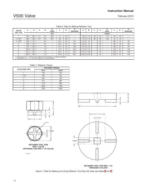
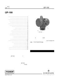
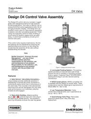
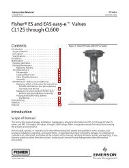
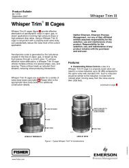
<strong>V500</strong> <strong>Valve</strong>Instruction ManualFebruary 2010VALVESIZE, NPSA B C DE(HEX)mmTable 6. Data for Making Retainer ToolFGH(SQUARE)A B C D1 26.9 28.4 9.7 6.4 28.4 1.5 4.8 - - - 1.06 1.12 .38 .25 1.12 .06 .19 - - -11/2 (1) 36.6 28.4 9.7 6.4 38.1 3.0 4.8 - - - 1.44 1.12 .38 .25 1.50 .12 .19 - - -11/2 (2) 36.6 19.1 - - - 6.4 - - - 22.4 4.8 12.7 1.44 .75 - - - .25 - - - .88 .19 .502 55.6 19.1 - - - 6.4 - - - 22.4 4.8 12.7 2.19 .75 - - - .25 - - - .88 .19 .503 79.2 33.3 - - - 7.9 - - - 41.4 7.9 19.0 3.12 1.31 - - - .31 - - - 1.62 .31 .75E(HEX)InchesFGH(SQUARE)4 104.6 33.3 - - - 7.9 - - - 41.4 7.9 25.4 4.12 1.31 - - - .31 - - - 1.62 .31 1.006 155.4 38.1 - - - 11.2 - - - 63.5 11.2 25.4 6.12 1.50 - - - .44 - - - 2.50 .44 1.008 203.2 50.8 - - - 11.2 - - - 101.6 11.2 38.1 8.00 2.00 - - - .44 - - - 4.00 .44 1.501. Dimensions for 11/2 inch tool made from hex barstock, an optional material.2. Dimensions for 11/2 inch tool made from round barstock.Table 7. Retainer TorqueRETAINER TORQUEVALVE SIZE, NPSNmLbfft1 140 10011/2 185 1352 260 1903 515 3804 1170 8606 2305 17008 3120 2300RETAINER TOOL FORNPS 1 VALVE(OPTIONAL FOR NPS 11/2 VALVE)B1899-2 / ILRETAINER TOOL FOR NPS 11/2THROUGH 8 VALVESFigure 7. Data for Making and Using Retainer Tool (Key 33) (also see tables 6 and 7)12
Instruction ManualFebruary 2010<strong>V500</strong> <strong>Valve</strong>VALVE SIZETable 8. Assembly ClearanceSEAT RING AND RETAINER CLEARANCEmmInchesNPS Min Max Min Max2 0.05 0.17 0.002 0.0073, 4, 6, and 8 0.08 0.30 0.003 0.012NoteThe seat ring (key 4) may have one ortwo shutoff surfaces. The shutoffsurfaces are the narrow, roundededges of the seat ring bore. Inspect theseat ring and locate the shutoffsurfaces before proceeding.4. Insert the seat ring into the seat ring cavity withthe correct shutoff surface facing the valve plug andshaft. The seat ring will cover the face seal installedin step 3.5. Place the second face seal on the seat ring.6. Apply anti-seize lubricant to the gasket surface inthe valve body. Install the gasket (key 11), whilemaking certain that for NPS 2 through 8 sizes theconcave surface of the gasket is up (hump surfaceof gasket down).7. Apply anti-seize lubricant to the threads andbottom of the retainer (key 5). Thread the retainerinto the valve body.8. Refer to figure 7. With the appropriate torqueindicating tool, tighten the retainer to the torquelisted in table 7.9. A gap between the seat ring (key 4) and retainer(key 5) allows the seat ring to self-center. Applyingthe proper amount of torque during installationshould position the retainer and seat ring properly.However, for NPS 2 through 8 valves, use a feelergauge to measure between the parts as shown infigure 13, making certain the necessary clearanceexists. Compare the measured gap to the clearancein table 8 and proceed as follows: If the measured clearance is within tablevalues, proceed to the next step. If the measured gap is larger than themaximum, tighten the retainer—apply more torquethan that listed in table 7, if necessary—until theclearance is within maximum and minimum values. If the measured clearance is smaller than theminimum, remove the retainer, seat ring, and faceseals, clean the parts, and reassemble so as toobtain the necessary clearance.10. Perform the Adjusting Actuator Travel procedureand then install the control valve in the pipeline.Replacing <strong>Valve</strong> Plug, Shaft, andBearingsPerform this procedure to replace the valve plug(key 2), expansion pin assembly (keys 9 and 10),shaft (key 3), or bearings (key 6). These parts areindependently replaceable; for example, installing anew valve plug does not require replacing a reusablevalve shaft or expansion pin assembly. Key numbersrefer to figures 11 and 13 unless otherwiseindicated.Disassembly of <strong>Valve</strong> Plug, Shaft, andBearingsWARNINGTo avoid personal injury resulting fromcontact with edges of the valve plug(key 2) and seat ring (key 4) duringplug rotation, stay clear of the plugedges when rotating the plug. To avoiddamage to tools, valve parts, or otheritems resulting from valve plugrotation, keep tools and other propertyaway from the edges of the plug.CAUTIONTo avoid increased leakage, increasedvalve component wear or possibledamage to the valve body (key 1), plug(key 2), shaft (key 3), and bearings (key6) resulting from a sharp blow to theactuator body or valve parts, use awheel puller to separate the actuatorparts from the valve shaft.Do not drive the actuator parts off thevalve shaft since this could move thevalve bearings, shaft, and plug awayfrom proper alignment, causingimproper seating of the plug. Suchmisalignment may result in damage tovalve components if the valve isreturned to service withoutdisassembly and inspection of thevalve plug alignment.13