Fisher V500 Rotary Control Valve
Fisher V500 Rotary Control Valve
Fisher V500 Rotary Control Valve

Create successful ePaper yourself
Turn your PDF publications into a flip-book with our unique Google optimized e-Paper software.
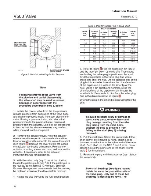
<strong>V500</strong> <strong>Valve</strong>Instruction ManualFebruary 2010VALVESIZE,NPSTable 9. Data for Tapped Hole in <strong>Valve</strong> ShaftSHAFT DIAMETERSThrough<strong>Valve</strong>BodyAt SplineEndThrough<strong>Valve</strong>BodyAt SplineEndTHREADSIZE,UNCmm mm Inches1 12.7 12.7 0.50 0.50 10-2411/2 15.9 15.9 0.62 0.62 1/4-202 15.9 12.7 0.62 0.62 10-24325.4 15.9 1.00 1.00 3/8-1625.4 25.4 1.00 0.75 5/16-184 31.8 19.1 1.25 1.25 3/8-16638.1 38.1 1.50 1.50 1/2-1338.1 31.8 1.50 1.25 3/8-168 38.1 38.1 1.50 1.50 1/2-13A3307-1 / ILFigure 8. Detail of <strong>Valve</strong> Plug for Pin RemovalNoteFollowing removal of the valve fromthe pipeline and partial disassembly,the valve shaft may be used to removebearings in accordance with theprocedure described in step 8, below.1. Isolate the control valve from the line pressure,release pressure from both sides of the valve body,and drain the process media from both sides of thevalve. If using a power actuator, also shut off allpressure lines to the power actuator, release allpressure from the actuator. Use lock-out proceduresto be sure that the above measures stay in effectwhile you work on the equipment.2. Remove the actuator cover. Note the actuatororientation with respect to the valve body and thelever orientation with respect to the valve drive shaft(see figure 2). Remove the lever but do not loosenthe actuator turnbuckle adjustment. Remove theactuator mounting screws and nuts, and remove theactuator. If necessary, refer to the actuatorinstruction manual for assistance.3. With the valve body (key 1) out of the pipeline,loosen the packing nuts (key 16). If the packing is tobe reused, do not remove it. However, EmersonProcess Management recommends that the packingbe replaced whenever the drive shaft is removed.4. Rotate the plug (key 2) to the fully open position.5. Refer to figure 8. Find the expansion pin (key 9)and the taper pin (key 10) inside of it. These partsare holding the valve plug in position on the shaft.Find the larger hole in the valve plug hub wherethese pins enter the hub. On the opposite side of theplug hub is a smaller hole where the chamfered endof the expansion pin rests on the inner lip of thehole. Using a pin punch and hammer, strike thechamfered end of the expansion pin through thesmaller hole. Remove both pins from the valve plughub in the direction shown in figure 8.Driving the pins in the other direction will tighten thepins.WARNINGTo avoid personal injury or damage totools, valve parts, or other items andplug damage resulting from the valveplug falling from the valve body,support the plug to prevent it fromfalling as the shaft (key 3) is beingremoved.6. Pull the shaft (key 3) from the valve body. If theshaft cannot be removed by hand, attach a slidehammer or similar tool to the spline end of the valveshaft. Each shaft, on the NPS 6 and 8 sizes, has atapped hole at the spline end of the shaft; refer totable 9 for thread sizes.7. Remove the plug and thrust washer (key 12) fromthe valve body.NoteTwo shaft bearings (key 6) are locatedinside the valve body on either side ofthe valve plug. Only one of these twobearings is identified by key 6. The14