Fisher V500 Rotary Control Valve
Fisher V500 Rotary Control Valve
Fisher V500 Rotary Control Valve

Create successful ePaper yourself
Turn your PDF publications into a flip-book with our unique Google optimized e-Paper software.
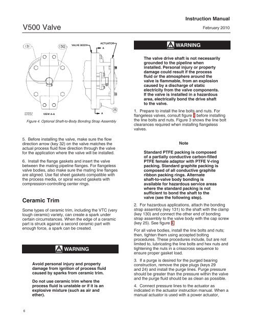
<strong>V500</strong> <strong>Valve</strong>Instruction ManualFebruary 2010VALVE BODYACTUATORAWARNING37A6528-AA3143-2/ILVIEW A-AFigure 4. Optional Shaft-to-Body Bonding Strap Assembly5. Before installing the valve, make sure the flowdirection arrow (key 32) on the valve matches theactual process fluid flow direction through the valvefor the application where the valve will be installed.6. Install the flange gaskets and insert the valvebetween the mating pipeline flanges. For flangelessvalve bodies, also make sure the mating line flangesare aligned. Use flat sheet gaskets compatible withthe process media, or spiral wound gaskets withcompression-controlling center rings.Ceramic TrimSome types of ceramic trim, including the VTC (verytough ceramic) variety, can create a spark undercertain circumstances. When the edge of a ceramicpart is struck against a second ceramic part withenough force, a spark can be created.WARNINGAvoid personal injury and propertydamage from ignition of process fluidcaused by sparks from ceramic trim.Do not use ceramic trim where theprocess fluid is unstable or if it is anexplosive mixture (such as air andether).AThe valve drive shaft is not necessarilygrounded to the pipeline wheninstalled. Personal injury or propertydamage could result if the processfluid or the atmosphere around thevalve is flammable, from an explosioncaused by a discharge of staticelectricity from the valve components.If the valve is installed in a hazardousarea, electrically bond the drive shaftto the valve.1. Prepare to install the line bolts and nuts. Forflangeless valves, consult figure 3 before installingthe line bolts and nuts. Figure 3 shows the line boltclearances required when installing flangelessvalves.NoteStandard PTFE packing is composedof a partially conductive carbon-filledPTFE female adaptor with PTFE V-ringpacking. Standard graphite packing iscomposed of all conductive graphiteribbon packing rings. Alternateshaft-to-valve body bonding isavailable for hazardous service areaswhere the standard packing is notsufficient to bond the shaft to thevalve (see the following step).2. For hazardous applications, attach the bondingstrap assembly (key 131) to the shaft with the clamp(key 130) and connect the other end of bondingstrap assembly to the valve body with the cap screw(key 25). See figure 4.For all valve bodies, install the line bolts and nuts;then, tighten them using accepted boltingprocedures. These procedures include, but are notlimited to, lubricating the line bolts and hex nuts andtightening the nuts in a crisscross sequence toensure proper gasket load.3. If a purge is desired for the purged bearingconstruction, remove the pipe plugs (keys 29and 24) and install the purge lines. Purge pressureshould be greater than the pressure within the valveand the purge fluid should be as clean as possible.4. Connect pressure lines to the actuator asindicated in the actuator instruction manual. When amanual actuator is used with a power actuator,6