TPV GENERATORS USING THE RADIANT TUBE ... - JX Crystals
TPV GENERATORS USING THE RADIANT TUBE ... - JX Crystals
TPV GENERATORS USING THE RADIANT TUBE ... - JX Crystals

Create successful ePaper yourself
Turn your PDF publications into a flip-book with our unique Google optimized e-Paper software.
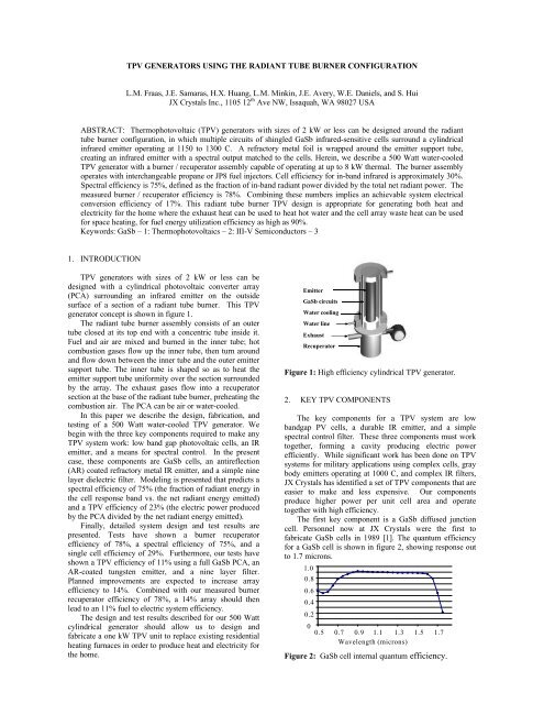
The process used to fabricate this cell replicates siliconsolar cell processing, using inexpensive diffusion stepswith no toxic gases, in contrast with epitaxy. <strong>JX</strong> <strong>Crystals</strong>has patents and licenses on GaSb cells and circuits [2].The second key component in our <strong>TPV</strong> system is anantireflection (AR) coated refractory metal emitter. Theconcept resembles the incandescent light bulb. Metals liketungsten (W) have low emittance at long wavelengths andhigher emittance at shorter wavelengths. In our IR emitter,the AR coating amplifies the material emittance in the cellconvertible band for wavelengths less than 1.7 microns [3],as detailed in <strong>JX</strong> <strong>Crystals</strong>’ issued patent [4].Referring to the measured emittance curve in figure 3,our IR emitter has an emittance over 0.7 in the cellconvertible band and a low emittance below 0.2 beyond 3.5microns. However, it is necessary to recycle the energyemitted in the 1.7 to 3.5 micron mid-wavelength band. Thiscan be done with a simple nine layer dielectric filter asshown in figure 4. This filter is fabricated with alternatinglayers of silicon and silicon dioxide.1.00.80.60.40.201 2 3 4 5micronsFigure 3: Measured emittance for AR coated tungsten.1.00.80.60.40.201 2 3 4 5micronsFigure 4: Reflectance for nine layer dielectric filter.3. BASIC <strong>THE</strong>ORY OF SPECTRAL CONTROLThe power spectrum passing through our filter from ourAR/W emitter can be calculated in two ways. The easierway is to assume normal incidence and perform an infinitesum for each wavelength. The second method uses aMonte Carlo program called TracePro, allows us to accountfor rays emitted at all angles given a 3D geometry. Infigure 5, the power spectra are displayed for both methodsassuming a 1300 C emitter. The geometry assumed for the3D case is a 3.3” φ cylindrical emitter with a 5” φphotovoltaic array and perfect end mirrors (an idealizedrepresentation). The filter suppresses the absorbed powerin the mid-wavelength band and the emitted power at longwavelengths is low. This means that there is good spectralcontrol; most of the power arriving at the cell array is in thecell response band. Also, note that the effect of rays withvarying angles (3D) is to broaden the power spectra peakrelative to the normal incidence (1D) case.Table I shows the predicted results using <strong>JX</strong> <strong>Crystals</strong>’three key components. Spectral efficiency is 75% and a<strong>TPV</strong> conversion efficiency of approximately 23% shouldbe possible. Note that the 3D case actually has slightlyhigher efficiency and power densities than the 1D case, apleasant surprise. These calculations are theoretical, usingreal component measured data. In the following sections,we describe a real and more complete <strong>TPV</strong> system.7654321Monte Carlo Model1D model01 2 3 4 5microns micronsFigure 5: Absorbed power spectra for 1D and 3D models.Table I: Model results for Temitter=1300° C, Tcell=50° C,3.3” φ emitter, 5” φ cell array (view factor=0.66),and perfect end mirrors.1D 3DIsc (A/cm 2 ) 3.52 3.98Voc 0.444 0.447Fill factor 0.728 0.725Pmax (W/cm 2 ) 1.15 1.30Pin(total) (W/cm 2 ) 5.16 5.53Pin(inband) (W/cm 2 ) 3.80 4.17Spectral efficiency 73.6% 75.4%Pmax / Pin(total) 22.3% 23.4%Pmax / Pin(inband) 30.3% 31.1%4. GENERATOR DESIGN AND FABRICATIONA tungsten emitter can not be operated in air. Thisintroduces a requirement for operation in an inert gas andconsequently a need for a tightly sealed enclosure. Whilethis requirement may appear daunting, it is encouragingthat common light bulbs are sealed and operate with thetungsten filament at 2800 C. Furthermore, conduction andconvection losses from the emitter to the PCA aresignificant in air and can be reduced by a factor of threewith Krypton backfill.The vertical cross section depicted in Figure 6 showsmore detail for our <strong>TPV</strong> generator design. Note that inorder to keep the hermetic seal between the PCA and theemitter support tube from overheating and to avoid heatlosses at this seal, there is a fold back section in the emittersupport tube. Besides reducing heat losses at the seal, thisfold back section also leads to a more efficient and compactdual-disc recuperator design.Figure 7 shows the inner disc stack that is used in ourrecuperator. In this inner stack, hot exhaust gases flowdown in contact with the outer fins which capture heat andtransfer it to the combustion air flowing upward inside incontact with the inner fins. Referring to figure 6, there is asecond larger diameter finned disc stack concentric withthis inner finned stack.
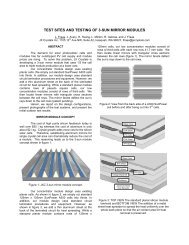
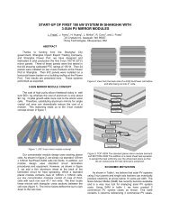
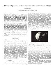
At the base of the recuperator, the hot but now coolerexhaust gases turn and enter the inside of the outer discstack, transfering heat outward to the incoming combustionair. Note that the inner stack temperature is higher than theouter stack temperature. The inner stack is fabricated usingInconel at its top and stainless steel at its bottom, whereasthe outer stack can be fabricated from aluminum. Theoperating unit discussed in the next section uses Kanthalfor the emitter support tube in the burner/recuperator.5. EXPERIMENTAL RESULTSUsing the design in figure 6, we have fabricated theburner-recuperator shown under test in figure 9a. Thisburner can operate at fuel flow rates of up to 8 kW thermal.By measuring the exhaust temperature at various burnrates, we have measured a burner-recuperator efficiencyranging between 73% and 78%, with the higher efficiencyoccurring at the lower flow rates. Figure 9b shows theassembled system, with the surrounding PCA.In our first experiment, we surrounded our burnerrecuperatorunit with an AR coated tungsten foil emitterand surrounded that with a quartz envelope. We coated thequartz envelope with a simple dielectric filter and backfilled the space between the emitter and the quartz withArgon. We then operated the emitter at 1275 C andmeasured the electrical output from a single water-cooledGaSb cell, as previously reported [3]. We measured a cellelectrical power output of one W/cm 2 and we measured aburner recuperator efficiency of 75%. We deduced aspectral efficiency of 74% and a cell efficiency of 29%.These single cell measurements are in very good agreementwith the performance predictions presented in Table I.Figure 6: Vertical cross section of the cylindrical <strong>TPV</strong>generator with recuperator.Figure 9a: Figure 9b:Glowing IR emitter. Water-cooled PCA.Figure 7: Laser cut rings and finned discs, pressedtogether for heat exchanger column.The PCA shown in figure 8 can generate 600 Watts. Itis an octagonal copper tube, 15 cm in diameter and 30 cmlong, with eight <strong>TPV</strong> circuits bonded to the inner facets.Each circuit is 5 cm by 27.5 cm and has three parallel rowsof 24 series connected GaSb cells, for a total of 72 cells percircuit and 576 cells in all. The back edge of each cellconnected to a front bus at the edge of the next cell. Thenine layer filters are deposited directly onto each cell at thewafer level before wafer dicing.Figure 8: <strong>JX</strong> <strong>Crystals</strong>’ <strong>TPV</strong> array with 576 GaSb cells.While our single cell measurements are encouraging, asingle cell is not a full array. We have tested our 576 cellPCA in a test station equipped with halogen lamps, thoughwe have not yet tested this array in combination with ourradiant tube burner. In a companion paper [5] in thisconference, we describe related PCA tests done incombination with an AR/W emitter. In those tests, wereport a <strong>TPV</strong> circuit efficiency of 11%. Through thistesting, we have identified the following issues associatedwith a full array operation:1. Emitter temperature must be uniform, as in figure 9a.While we can obtain good uniformity, this takes someiterative development and testing.2. Cell quantum efficiencies are somewhat lower than thebest research cell QE shown in fig. 2. System work canproceed using today’s cells.3. Circuit series resistance must be low. While this is not afundamental problem, development time is required.4. End mirrors are required to avoid non-uniformity andend losses; they must be highly reflective and wellconnected to the PCA for cooling. This is especiallyimportant for smaller systems, but not yet addressed.5. Cracks and steps between cells in circuits representparasitic losses that increase cavity absorption. This candegrade system performance. We discuss this more fullyin the next section.
6. PLANNED IMPROVEMENTSReferring to the PCA shown in figure 8, notice that thesteps in the shingle circuits are clearly visible. It is clearthat there are steps and cracks in the circuits where thereare no filter coatings. Depositing our nine layer filters onglass slides and silicone bonding these glass slides on topof the shingle circuits can cover the steps and cracks. Wehave run a TracePro analysis for two different PCAs withand without planar filters, as summarized in Table II.TracePro analysis shows that an improvement in <strong>TPV</strong>efficiency from 12.8% to 14.4% should result when planarfilters are used. We have fabricated a circuit with planarfilter covers as shown in figure 10 and tested it for output at50 C. The I vs. V results shown in figure 11 indicate thateight of these circuits in a PCA are capable of producing600 Watts of electrical power.Table II: TracePro energy flow and efficiency for PCAwith shingle circuits with steps and cracks vs. PCA withthe same circuits with a planar filter covers.Temitter=1200 C and Tcell=50 C.ShinglecircuitsCircuitswith filtersPCA Ptotal (W) 7,276.4 7,277.8End escape (W) 265.8 340.7Recycled (W) 2,914.6 3,267.7Pmax (W) 557.0 575.0Pwater (W) 4,096.1 3,648.9Ptotal-Precycle (W) 4,361.9 3,990.1Pmax/(Ptotal-Precycle) 12.77% 14.41%Efficiency(burner/recup) 75% 75%Efficiency(system) 9.58% 10.81%Figure 10: Shingle circuit with and without planar filters.7. ECONOMICS AND MARKETSResidential <strong>TPV</strong> systems are replacements for homefurnaces, but offer two significant benefits. First, theelectricity that is generated will offset electric utilitypayments, with a payback period for the <strong>TPV</strong> system ofjust three to five years. And second, <strong>TPV</strong> systems canoperate independent of the electric grid; traditional naturalgas furnaces stop working without electricity for their fans.We forecast that a 1 kW <strong>TPV</strong> cogenerator of heat andelectricity could be sold for $2,000 more than the cost of atraditional furnace with the same heat output. An analysisof natural gas consumption in the central and northeasternUnited States indicates that such a system wouldcogenerate $675 worth of electricity (at 2004 rates), for apayback of three years. In new construction, it would bevery simple to include the capital cost into a home loan,with the annual electric bill savings far outstripping theadditional annual cost on the loan. The additional benefitof reliable heat, even when the power grid is down, isworth at least the cost of traditional 1 kW generators.8. CONCLUSIONSHerein, we have described three <strong>TPV</strong> key componentsthat together represent a novel approach to obtaining high<strong>TPV</strong> conversion efficiency. The newest component is theAR coated refractory metal emitter. A TracePro 3D modelfor a complete system using these components indicatesthat a <strong>TPV</strong> efficiency of 23% should be achievable. Wehave fabricated a radiant tube burner and measured itschemical to radiation efficiency to be 75%. When wesurround this full size burner with a full size AR/W emitterfoil and filter cylinder, operate it at 1275° C, and measurethe output from a single cell, we measure a cell output ofone W/cm 2 which is very consistent with the TraceProprediction. However, there are issues in building a full sizearray that a single cell measurement does not address.We further described the design and fabrication of acomplete <strong>TPV</strong> generator, including a full-size PCA andprovisions for operating the AR/W emitter in an inertatmosphere. Modeling of this system implies that a <strong>TPV</strong>efficiency of 14.4% for a full array should be possibleusing today’s components. This would yield a system fuelto electric efficiency of 10.8%. Higher system efficiency ispossible through an increase in average cell quantumefficiency and/or a decrease in circuit series resistance.REFERENCESPmax = 75.49Vmax = 7.44Imax = 10.15Voc = 10.46Isc = 11.52FF = 0.626Figure 11: I vs. V for circuit with planar filter at 50 C.1. L.M. Fraas, J.E. Avery, V.S. Sundaram, et. al.“Fundamental Characterization Studies of GaSb SolarCells”, 22 nd IEEE PVSC (1991) p. 80.2. US Patents #5,217,539, #5,389,158, #6,057,507,#6,232,545 B1, and PCTs.3. L.M. Fraas, J.E. Samaras, J.E. Avery, andL.M. Minkin, “AR Coated Refractory Metal MatchedEmitter for Use with GaSb <strong>TPV</strong> Generators”,28 th IEEE PVSC (2000) p. 1020.4. US Patent # 6,177,628 and PCT.5. L.M. Fraas et. al., companion paper in this conference.