SAILOR 500/250 FleetBroadband
SAILOR 500/250 FleetBroadband
SAILOR 500/250 FleetBroadband

Create successful ePaper yourself
Turn your PDF publications into a flip-book with our unique Google optimized e-Paper software.
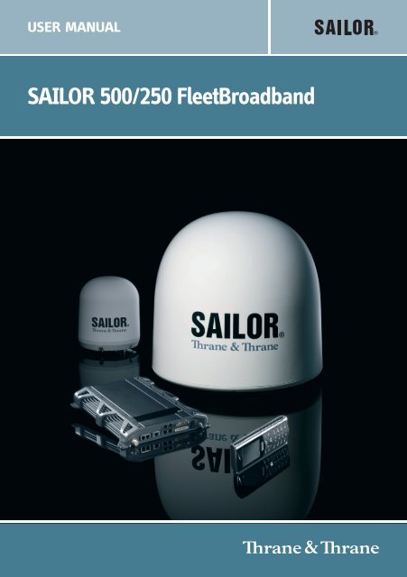
USER MANUAL<strong>SAILOR</strong> <strong>500</strong>/<strong>250</strong> <strong>FleetBroadband</strong>
Thrane & Thrane A/S<strong>SAILOR</strong> ® <strong>500</strong> <strong>FleetBroadband</strong><strong>SAILOR</strong> ® <strong>250</strong> <strong>FleetBroadband</strong>User manualDocument number: TT98-125645-CRelease date: December 12, 2007
Information in this document is subject to change without notice and does not representa commitment on the part of Thrane & Thrane A/S. We recommend downloading thelatest version of the manual from the Thrane & Thrane Extranet.Copyright © 2007 Thrane & Thrane A/S. All rights reserved.Trademark acknowledgements:• Thrane & Thrane is a registered trademark of Thrane & Thrane A/S in the EuropeanUnion and the United States.• <strong>SAILOR</strong> is a registered trademark of Thrane & Thrane A/S in the European Union, theUnited States and other countries.• Windows and Outlook are registered trademarks of Microsoft Corporation in theUnited States and other countries.• Inmarsat is a registered trademark of International Maritime Satellite Organisation(IMSO) and is licensed by IMSO to Inmarsat Limited and Inmarsat Ventures plc.• Inmarsat’s product names are trademarks or registered trademarks of Inmarsat.• Other product and company names mentioned in this manual may be trademarks ortrade names of their respective owners.Company addresseswww.thrane.comDenmarkThrane & Thrane Aalborg A/SPorsvej 2DK-9200 Aalborg SVDenmarkDenmarkCompany headquartersThrane & Thrane A/SLundtoftegårdsvej 93 DDK-2800 Kgs. LyngbyDenmarkNorwayThrane & Thrane NorwayBergerveien 12PO Box 911375 Billingstad,NorwayUSAThrane & Thrane, Inc.509 Viking Drive, SuitesK, L and MVirginia Beach, VA 23452USAChinaThrane & Thrane ShanghaiUnit 602 - Building 4,289 Bisheng Rd.Zhangjiang High-tech Park,Pudong201204 ShanghaiP. R. China
Safety summary 1The following general safety precautions must be observed during allphases of operation, service and repair of this equipment. Failure to complywith these precautions or with specific warnings elsewhere in this manualviolates safety standards of design, manufacture and intended use of theequipment. Thrane & Thrane A/S assumes no liability for the customer'sfailure to comply with these requirements.Observe marked areasUnder extreme heat conditions do not touchareas of the terminal or antenna that aremarked with this symbol, as it may result ininjury.Microwave radiation hazardsDuring transmission the antenna in this system radiates MicrowavePower.This radiation may be hazardous to humans close to the antenna.During transmission, make sure that nobody gets closer than therecommended minimum safety distance.On the <strong>SAILOR</strong> <strong>500</strong> <strong>FleetBroadband</strong>, theminimum safety distance on the focal line tothe antenna panel is 1.3 m, based on aradiation level of 10 W/m 2 . The radiation level is100 W/m 2 at a distance of 0.4 m from theantenna panel. Refer to the drawing on thenext page.On the <strong>SAILOR</strong> <strong>250</strong> <strong>FleetBroadband</strong>, theminimum safety distance on the focal line tothe antenna panel is 0.6 m, based on aradiation level of 10 W/m 2 . The radiation level is100 W/m 2 at a distance of 0.2 m from theantenna panel. Refer to the drawing on thenext page.iii
MICROWAVE RADIATIONNo personnel within safety distanceSafety distance:<strong>SAILOR</strong> <strong>500</strong>:1.3 m, 10 W/m 2(0.4 m, 100 W/m 2 )<strong>SAILOR</strong> <strong>250</strong>:0.6 m, 10 W/m 2(0.2 m, 100 W/m 2 )25° for <strong>SAILOR</strong> <strong>500</strong>60° for <strong>SAILOR</strong> <strong>250</strong>Distance to other equipmentDo not move the antenna closer to radars than the minimum safe distancespecified in the installation manual - it may cause damage to the antenna.The equipment must be installed with the following minimum safe distancesto magnetic steering compass:<strong>SAILOR</strong> <strong>FleetBroadband</strong> terminal: min. 0.3 m.<strong>SAILOR</strong> <strong>500</strong> <strong>FleetBroadband</strong> antenna: min. 1.0 m<strong>SAILOR</strong> <strong>250</strong> <strong>FleetBroadband</strong> antenna: min. 1.1 mServiceUser access to the interior of the terminal is prohibited. Only a technicianauthorized by Thrane & Thrane A/S may perform service - failure to complywith this rule will void the warranty. Access to the interior of the antenna isallowed, but only for replacement of certain modules - as described in theInstallation manual. General service may only be performed by a technicianauthorized by Thrane & Thrane A/S.Do not service or adjust aloneDo not attempt internal service or adjustments unless another person,capable of rendering first aid resuscitation, is present.iv
Grounding, cables and connectionsTo minimize shock hazard, the equipment chassis and cabinet must beconnected to an electrical ground. Both terminal and antenna must begrounded to the ship. For further grounding information refer to theInstallation manual.Do not extend the cables beyond the lengths specified for the equipment.The cable between the terminal and antenna can be extended if it complieswith the specified data concerning cable losses etc.All cables for the <strong>SAILOR</strong> <strong>FleetBroadband</strong> system are shielded and shouldnot be affected by magnetic fields. However, try to avoid running cablesparallel to AC wiring as it might cause malfunction of the equipment.Power supplyThe voltage range is 10.5 - 32 V DC; 14 A - 5.5 A. It is recommended that thevoltage is provided by the 24 V DC power bus on the ship. Be aware of highstart-up peak current: 20 A@24 V, 5 ms.If a 24 V DC power bus is not available, an external 115/230 VAC to 24 V DCpower supply can be used.Equipment ventilationTo ensure adequate cooling of the terminal, 5 cm of unobstructed spacemust be maintained around all sides of the unit (except the bottom side).The ambient temperature range of the terminal is: -25° to +55°C.Do not operate in an explosive atmosphereDo not operate the equipment in the presence of flammable gases or fumes.Operation of any electrical equipment in such an environment constitutes adefinite safety hazard.Keep away from live circuitsOperating personnel must not remove equipment covers. Componentreplacement and internal adjustment must be made by qualifiedmaintenance personnel. Do not replace components with the power cableconnected. Under certain conditions, dangerous voltages may exist evenwith the power cable removed. To avoid injuries, always disconnect powerand discharge circuits before touching them.Failure to comply with the rules above will void the warranty!v
Mandatory safety instructions to installers &users of <strong>SAILOR</strong> ® <strong>250</strong> <strong>FleetBroadband</strong> 2Use only manufacturer or dealer supplied antenna.Antenna minimum safe distance: 0.415 m.Antenna gain 12.2 dBi referenced to isotropic.Antenna mountingAntenna substitutionThe Federal Communications Commission has adopted a safetystandard for human exposure to RF (Radio Frequency) energy,which is below the OSHA (Occupational Safety and Health Act)limits.The antenna supplied by the manufacturer or radio dealer mustnot be mounted at a location such that during radio transmission,any person or persons can come closer than the above indicatedminimum safe distance to the antenna i.e. 0.415 m.To comply with current FCC RF Exposure limits, the antenna mustbe installed at or exceeding the minimum safe distance shownabove, and in accordance with the requirements of the antennamanufacturer or supplier.Base Station Installation: The antenna should be fixed-mountedon an outdoor permanent structure. RF Exposure compliance mustbe addressed at the time of installation.Do not substitute any antenna for the one supplied orrecommended by the manufacturer or radio dealer. You may beexposing person or persons to excess radio frequency radiation.You may contact your radio dealer or the manufacturer for furtherinstructions.vi
WarningMaintain a separation distance from the antenna to a person(s) ofat least 0.415 m.NoteThrane & Thrane recommends a minimum safetydistance of 0.6 m to the <strong>SAILOR</strong> <strong>250</strong> <strong>FleetBroadband</strong>antenna.You, as the qualified end-user of this radio device must control theexposure conditions of bystanders to ensure the minimumseparation distance (above) is maintained between the antennaand nearby persons for satisfying RF Exposure compliance. Theoperation of this transmitter must satisfy the requirements ofOccupational/Controlled Exposure Environment, for work-relateduse. Transmit only when person(s) are at least the minimumdistance from the properly installed, externally mounted antenna.vii
About the manual 3Intended readersManual overviewThis manual is a user manual for the <strong>SAILOR</strong> <strong>500</strong> <strong>FleetBroadband</strong>system and the <strong>SAILOR</strong> <strong>250</strong> <strong>FleetBroadband</strong> system. The readers ofthe manual include anyone who is using or intends to use one ofthese two systems. No specific skills are required to operate the<strong>SAILOR</strong> <strong>FleetBroadband</strong> system. However, it is important that youobserve all safety requirements listed in the beginning of thismanual, and operate the system according to the guidelines in thismanual.Note that this manual does not cover installation nor does it coverhow to use the IP handset that comes with the system. Forinformation on installation refer to the installation manual and forinformation on the IP handset refer to the user manual for the IPhandset. Part numbers for both manuals are listed in the nextsection.This manual has the following chapters:• Introduction contains an overview of the BGAN services and abrief description of the system.• Getting started explains how to insert SIM card and start up theunit. It also contains a short guide to making the first call.• Operating the system explains how to use the system.• Using the web interface explains how to use the built-in webinterface of the terminal, and describes the available menusand settings, including advanced setup of interfaces.• Troubleshooting contains a short troubleshooting guide andexplains how to update software. It also describes the functionsof the light indicators and the Reset button, and givesinformation on where to get further help if needed.viii
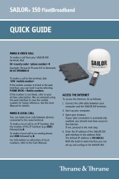
Related documentsThis manual may not always reflect the latest softwarefunctionality of your terminal. To obtain the latest version of themanual, please enter the Thrane & Thrane Extranet and downloadthe latest version, or acquire it from your distributor.The below list shows the documents related to this manual and tothe <strong>SAILOR</strong> <strong>500</strong> <strong>FleetBroadband</strong> and <strong>SAILOR</strong> <strong>250</strong> <strong>FleetBroadband</strong>systems.Title and description<strong>SAILOR</strong> <strong>500</strong> <strong>FleetBroadband</strong><strong>SAILOR</strong> <strong>250</strong> <strong>FleetBroadband</strong>Installation ManualExplains how to install the<strong>SAILOR</strong> <strong>FleetBroadband</strong> terminal, the<strong>SAILOR</strong> <strong>500</strong> <strong>FleetBroadband</strong> antenna and the<strong>SAILOR</strong> <strong>250</strong> <strong>FleetBroadband</strong> antenna.<strong>SAILOR</strong> <strong>500</strong>/<strong>250</strong> <strong>FleetBroadband</strong>, Quick GuideA short guide to the most important functionsof the <strong>SAILOR</strong> <strong>FleetBroadband</strong> systems.Thrane & Thrane IP Handset, User ManualExplains the features and functions of theThrane & Thrane IP handset. The IP handsetworks as a standard IP handset, but also servesas a user interface for the<strong>SAILOR</strong> <strong>FleetBroadband</strong> systems.DocumentnumberTT 98-125646TT98-125647TT98-126059ix
TypographyIn this manual, typography is used as indicated below:Bold is used for the following purposes:• To emphasize words.Example: “Do not touch the antenna”.• To indicate what the user should select in the user interface.Example: “Select SETTINGS > LAN”.Italic is used to emphasize the paragraph title in cross-references.Example: “For further information, see Connecting Cables onpage...”.COURIER is used to indicate low level commands such as ATcommands.Example: “In your terminal program, type ATD”.x
Table of ContentsSafety summary ................................................................iiiMandatory safety instructions to installers & users of<strong>SAILOR</strong> ® <strong>250</strong> <strong>FleetBroadband</strong> ............................................ viAbout the manual ............................................................ viiiChapter 1Chapter 2IntroductionWelcome ............................................................................ 1In this chapter ....................................................................2Features and interfaces ......................................................3Main units ..........................................................................4<strong>SAILOR</strong> ® <strong>500</strong> <strong>FleetBroadband</strong>/ <strong>SAILOR</strong> ® <strong>250</strong> <strong>FleetBroadband</strong> ......4Units overview ......................................................................4<strong>SAILOR</strong> <strong>FleetBroadband</strong> antennas ...........................................5<strong>SAILOR</strong> <strong>FleetBroadband</strong> terminal ............................................7IP handset and cradle ...........................................................9The Inmarsat BGAN system ............................................... 11What is BGAN? .................................................................... 11The Inmarsat <strong>FleetBroadband</strong> service ..................................... 11Coverage ............................................................................12Overview of the <strong>FleetBroadband</strong> system ..................................13The BGAN services ...............................................................14Matrix of services and interfaces ......................................17What’s next? .................................................................... 18Getting startedIn this chapter ...................................................................19xi
Table of ContentsGetting started with the terminal ..................................... 19Operation at high temperatures ............................................ 19Connector panel ................................................................ 20Starting up the terminal ...................................................... 20Connecting the IP handset ................................................22Power supply ......................................................................22Starting up the IP handset ....................................................22Making the first data connection (LAN) .............................23Before connecting to the LAN interface ..................................23Connecting a computer to the LAN interface ...........................23Entering the SIM PIN for the terminal ...............................24Overview ............................................................................24Entering the PIN using a phone or IP handset ........................24Entering the PIN using the web interface ...............................26Connecting to the BGAN network ......................................27Making the first call .........................................................29Introduction .......................................................................29Making a call from the terminal ............................................29Making a call to the terminal ................................................29Making a call from one terminal to another ........................... 30What’s next? ................................................................... 30Chapter 3Operating the systemIn this chapter .................................................................. 31General ............................................................................ 31Tools for setup and use ........................................................ 31Services and interfaces ........................................................33xii
Table of ContentsUsing a phone or fax machine ..........................................34Available interfaces .............................................................34Selecting the call type .........................................................35Making or receiving a phone call ..........................................38Making a call to the terminal ................................................40Dialing functions .................................................................41Sending or receiving a fax message ......................................46Using a computer .............................................................48Available interfaces .............................................................48Standard or Streaming data on LAN ......................................48Working with network groups ..............................................50Using the IP handset .........................................................51What’s next? .....................................................................51Chapter 4Using the web interfaceIn this chapter ..................................................................53Introduction .....................................................................53The web interface ...............................................................53Accessing and navigating the web interface ...........................55Entering the SIM PIN in the web interface ........................58The Dashboard .................................................................59Overview ...........................................................................59Properties ..........................................................................60Managing data sessions .......................................................61Using the phone book ......................................................65General usage ....................................................................65Editing phone book entries ..................................................68Viewing and editing the mobile numbers ...............................69Using the Call log .............................................................70Information on total usage ...................................................70Exporting the call log ...........................................................71Viewing the lists of calls ...................................................... 72xiii
Table of ContentsHandling messages ..........................................................73Sending an SMS message ....................................................73Options for messages in the Outbox .......................................74Options for messages in the Sent folder .................................75Sending an SMS message to the terminal ..............................75Receiving a message ...........................................................76Options for new SMS messages ............................................77Options for SMS messages in the Inbox ..................................77Configuring message settings ...............................................78Setting up the interfaces .................................................. 80The SETTINGS page (Antenna properties) .............................. 80Enabling or disabling the L-Band interface ............................ 80Configuring the LAN interface ............................................... 81Configuring the Phone/Fax interface .................................... 85Configuring the ISDN interface .............................................87Setting the common interface settings .................................. 90Setting up call services ........................................................92Managing LAN network users ......................................... 99Overview ........................................................................... 99Setting up the network user groups ..................................... 100Managing network devices ................................................. 104The Network classification table .......................................... 106Definitions for network terms .............................................. 109Software upload and event log .........................................111Uploading software .............................................................111Viewing the Event list or the Event log .................................. 114Selecting the preferred BGAN satellite ............................. 116Administration ................................................................ 118Accessing the administration settings ................................... 118Call charges ......................................................................122Log handling .....................................................................123Using profiles ....................................................................124Using traffic flow filters ...................................................... 128Setting up user permissions ................................................ 131xiv
Table of ContentsHelp desk and diagnostic report ......................................133Accessing the Help desk .....................................................133Generating a diagnostic report ............................................134What’s next? ...................................................................134Chapter 5TroubleshootingIn this chapter .................................................................135Getting support ...............................................................135Overview ..........................................................................135Airtime support .................................................................135System support ..................................................................135Uploading software .........................................................136Viewing software version status ...........................................136Uploading software using the web interface ..........................136Spare parts, <strong>SAILOR</strong> ® <strong>500</strong> <strong>FleetBroadband</strong> ......................137Antenna spare parts ...........................................................137Cables ..............................................................................137Spare parts, <strong>SAILOR</strong> ® <strong>250</strong> <strong>FleetBroadband</strong> ......................138Cables ..............................................................................138Options and accessories ..................................................139Troubleshooting guide ....................................................140Status signaling ..............................................................146Overview ..........................................................................146Light indicators .................................................................146Event messages .................................................................150Logging of events ............................................................ 151Diagnostic report ............................................................... 151Event log .......................................................................... 151Reset button ....................................................................152How to access the Reset button ...........................................152Function of the Reset button ...............................................153xv
Table of ContentsChapter 6Conformity<strong>SAILOR</strong> ® <strong>500</strong> <strong>FleetBroadband</strong> ......................................... 155CE (R&TTE) ....................................................................... 155<strong>SAILOR</strong> ® <strong>250</strong> <strong>FleetBroadband</strong> ...........................................157CE (R&TTE) ........................................................................157FCC ..................................................................................157Glossary ....................................................................................... 159Index ....................................................................................... 163xvi
1111Chapter 1Introduction 1WelcomeIntroductionCongratulations on the purchase of your <strong>SAILOR</strong> <strong>FleetBroadband</strong> system!<strong>SAILOR</strong> <strong>500</strong> <strong>FleetBroadband</strong> and <strong>SAILOR</strong> <strong>250</strong> <strong>FleetBroadband</strong> are maritimebroadband systems, providing simultaneous high-speed data and voicecommunication via satellite through the Broadband Global Area Network(BGAN).1
Chapter 1: IntroductionApplications include:• Internet browsing• E-mail• Phone and fax services• Large file transfers• Video conferencing and Streaming• VPN (Virtual Private Network) access to corporate serversIn this chapterThis chapter introduces the <strong>SAILOR</strong> <strong>500</strong> <strong>FleetBroadband</strong> system and the<strong>SAILOR</strong> <strong>250</strong> <strong>FleetBroadband</strong> system, and gives an overview of the physicalunits and their features and functions.It also gives an overview of the BGAN system and services.2 In this chapter
Features and interfaces1111Chapter 1: IntroductionThe <strong>SAILOR</strong> <strong>FleetBroadband</strong> system offers the following features andinterfaces:• Simultaneous voice and data communication over BGAN• Full duplex, single or multi-user, up to:<strong>SAILOR</strong> <strong>500</strong> <strong>FleetBroadband</strong>: 432 kbps<strong>SAILOR</strong> <strong>250</strong> <strong>FleetBroadband</strong>: 284 kbps• Support for streaming IP at:<strong>SAILOR</strong> <strong>500</strong> <strong>FleetBroadband</strong>: 32, 64, 128, 256 kbps<strong>SAILOR</strong> <strong>250</strong> <strong>FleetBroadband</strong>: 32, 64, 128 kbps• ISDN service, only <strong>SAILOR</strong> <strong>500</strong> <strong>FleetBroadband</strong>: 64 kbps• Voice: Standard Voice (4.0 kbps) or 3.1 kHz Audio• 4 LAN ports with Power over Ethernet (PoE) for computers, e-hubs, IPhandsets etc.• 2 Standard Phone/Fax ports for standard phones, fax machines or analogmodems• 1 Euro ISDN port for ISDN phones or, for <strong>SAILOR</strong> <strong>500</strong> <strong>FleetBroadband</strong> only:G4 fax or ISDN modem• 1 L-Band output for connecting a broadcast receiver for maritime data• 1 multi-purpose I/O connector with 5 configurable inputs/outputs• 1 SIM slot for your BGAN SIM card• Integral DHCP/NAT router• Built-in web interface allowing you to manage your phone book,messages and calls, and customize the terminal to your specific needs• Input power: 10.5 - 32 V DC (14 A - 5.5 A)• CE certifiedIntroductionFeatures and interfaces 3
Chapter 1: IntroductionMain units<strong>SAILOR</strong> ® <strong>500</strong> <strong>FleetBroadband</strong>/ <strong>SAILOR</strong> ® <strong>250</strong> <strong>FleetBroadband</strong>The main difference between the <strong>SAILOR</strong> <strong>500</strong> <strong>FleetBroadband</strong> system and the<strong>SAILOR</strong> <strong>250</strong> <strong>FleetBroadband</strong> system lies in the antenna.• <strong>SAILOR</strong> <strong>500</strong> <strong>FleetBroadband</strong> uses the TT-3052A antenna, which is amaritime BGAN Class 8 antenna.This antenna is larger and provides more bandwidth than the TT-3050Aused for the <strong>SAILOR</strong> <strong>250</strong> <strong>FleetBroadband</strong> system.• <strong>SAILOR</strong> <strong>250</strong> <strong>FleetBroadband</strong> uses the TT-3050A antenna, which is amedium size, maritime BGAN Class 9 antenna.The <strong>SAILOR</strong> <strong>500</strong> <strong>FleetBroadband</strong> system and the <strong>SAILOR</strong> <strong>250</strong> <strong>FleetBroadband</strong>system basically use the same type of terminal, except that the<strong>SAILOR</strong> <strong>500</strong> <strong>FleetBroadband</strong> offers a few more features than the<strong>SAILOR</strong> <strong>250</strong> <strong>FleetBroadband</strong>. See Features and interfaces on page 3.Units overviewThe <strong>SAILOR</strong> <strong>500</strong> <strong>FleetBroadband</strong> system TT-3740A includes the following mainunits:• TT-3052A <strong>SAILOR</strong> <strong>500</strong> <strong>FleetBroadband</strong> antenna• TT-3738A <strong>SAILOR</strong> <strong>FleetBroadband</strong> terminal• TT-3670A IP handset with cradleThe <strong>SAILOR</strong> <strong>250</strong> <strong>FleetBroadband</strong> system TT-3742A includes the following mainunits:• TT-3050A <strong>SAILOR</strong> <strong>250</strong> <strong>FleetBroadband</strong> antenna• TT-3738A <strong>SAILOR</strong> <strong>FleetBroadband</strong> terminal• TT-3670A IP handset with cradle4 Main units
<strong>SAILOR</strong> <strong>FleetBroadband</strong> antennas1111Chapter 1: Introduction<strong>SAILOR</strong> ® <strong>500</strong> <strong>FleetBroadband</strong> antenna<strong>SAILOR</strong> <strong>500</strong> <strong>FleetBroadband</strong> system uses the TT-3052A antenna, which is amaritime BGAN antenna that complies with Inmarsat’s Class 8 definition formaritime antennas. The antenna contains all functions for satellite trackingincluding a GPS system. A single coaxial cable carries all RF communication,supply voltage and modem communication between the antenna and theterminal.IntroductionThis antenna is larger and provides more bandwidth than the TT-3050A usedfor the <strong>SAILOR</strong> <strong>250</strong> <strong>FleetBroadband</strong> system.Main units 5
Chapter 1: Introduction<strong>SAILOR</strong> ® <strong>250</strong> <strong>FleetBroadband</strong> antenna<strong>SAILOR</strong> <strong>250</strong> <strong>FleetBroadband</strong> system uses the TT-3050A antenna, which is amedium size, maritime BGAN Class 9 antenna.6 Main units
<strong>SAILOR</strong> <strong>FleetBroadband</strong> terminal1111Chapter 1: IntroductionOverviewWhether you have purchased a <strong>SAILOR</strong> <strong>500</strong> <strong>FleetBroadband</strong> system or a<strong>SAILOR</strong> <strong>250</strong> <strong>FleetBroadband</strong> system, the terminal is basically the same. Forthis reason this section covers both systems.The <strong>SAILOR</strong> <strong>FleetBroadband</strong> terminal is the controlling unit in the<strong>SAILOR</strong> <strong>FleetBroadband</strong> system. It contains all user interfaces and LEDindicators and stores configuration data.IntroductionTools for setup and daily useThe Thrane & Thrane IP handset is used for displaying status and for changingsimple parameters. For information on how to use the handset menus, see theuser manual for the IP handset.The built-in web interface is used for easy configuration and daily use. Theweb interface is accessed from a computer connected to the terminal, using anInternet browser. No installation of software is needed.For further information on the web interface, see Chapter 4, Using the webinterface.Main units 7
Chapter 1: IntroductionSIM cardThe terminal has a SIM slot (Subscriber Identity Module) located in theconnector panel behind a small cover plate.The terminal requires a dedicated <strong>FleetBroadband</strong> SIM card, which is acquiredfrom your Airtime Provider.The system requires a SIM card to go online and to access the settings of theterminal. However, using the web interface you can view the Dashboard andupload software without inserting a SIM card. Upload of software requires anAdministrator user name and password.For information of features and interfaces, see The Inmarsat BGAN system onpage 11.8 Main units
IP handset and cradle1111Chapter 1: IntroductionIP handsetIntroductionThe Thrane & Thrane IP handsetcommunicates using Internet protocols. Thehandset is not strictly dedicated to the<strong>SAILOR</strong> <strong>FleetBroadband</strong> system, but can alsobe used in a public network as a standard IPtelephone.When the IP handset is used with theterminal, it communicates using Internetprotocol between the handset and theterminal. However, on the BGAN networkside of the terminal, calls are transmitted ascircuit switched calls.The IP handset is powered directly from theLAN interface using Power over Ethernet(PoE).When connected to the terminal the IPhandset provides a dedicated menu with asubset of the terminal configuration options.For more information on the functions of theIP handset, refer to the user manual for theIP handset.Main units 9
Chapter 1: IntroductionIP cradleThe IP cradle serves as a holder for the IP handset.The handset is connected to the cradle with a coil cord. The cradle connects tothe terminal using an Ethernet cable.10 Main units
The Inmarsat BGAN systemWhat is BGAN?1111Chapter 1: IntroductionThe Broadband Global Area Network (BGAN) is a mobile satellite service thatoffers high-speed data up to 492 kbps and voice telephony. BGAN enablesusers to access e-mail, corporate networks and the Internet, transfer files andmake telephone calls.IntroductionThe Inmarsat <strong>FleetBroadband</strong> service<strong>FleetBroadband</strong> is a maritime communications service offered in the BGANsystem. Based on 3G standards, <strong>FleetBroadband</strong> provides cost-effectivebroadband data and voice simultaneously.The Inmarsat BGAN system 11
Chapter 1: IntroductionCoverageThe Inmarsat BGAN services are based on geostationary satellites situatedabove the equator. Each satellite covers a certain area (footprint). Thecoverage map below shows the footprints of the BGAN system.(Launch dateto be finalized)NoteNoteThe map depicts Inmarsat's expectations of coverage, but does notrepresent a guarantee of service. The availability of service at theedge of coverage areas fluctuates depending on various conditions.The launch date of the F3 satellite (POR) will be determined in duecourse.Certain <strong>FleetBroadband</strong> services are not available in areas with lowelevation. For further information, see Limitations on page 16.12 The Inmarsat BGAN system
Overview of the <strong>FleetBroadband</strong> system1111Chapter 1: IntroductionA complete BGAN <strong>FleetBroadband</strong> system may include the<strong>SAILOR</strong> <strong>FleetBroadband</strong> terminal with connected peripherals, a<strong>SAILOR</strong> <strong>500</strong> <strong>FleetBroadband</strong> antenna or a <strong>SAILOR</strong> <strong>250</strong> <strong>FleetBroadband</strong>antenna, the BGAN satellite, and the Satellite Access Station (SAS). Thesatellites are the connection between your terminal and the SAS, which is thegateway to the worldwide networks (Internet, telephone network, cellularnetwork, etc.).IntroductionPacket Switched NetworkSatelliteIP RouterPC<strong>SAILOR</strong> <strong>250</strong><strong>FleetBroadband</strong>antenna<strong>SAILOR</strong> <strong>500</strong><strong>FleetBroadband</strong>antennaSatellite Access Station(SAS)SwitchStandard voiceand ISDN<strong>SAILOR</strong><strong>FleetBroadband</strong>terminalCircuit Switched NetworkIP HandsetThe Inmarsat BGAN system 13
Chapter 1: IntroductionThe BGAN servicesSupported servicesThe services currently supported by BGAN comprise:• A Packet Switched connection to the Internet• A Circuit Switched (Dialed) connection for voice, fax or data• Short Messaging Service (SMS)Packet data serviceThe BGAN network supports different classes of data connection to theInternet.• Using a Standard data connection several users can share the dataconnection simultaneously. This type of connection is ideal for e-mail, filetransfer, and Internet and intranet access. The user pays for the amount ofdata sent and received.• Using a Streaming data connection you get an exclusive high-priorityconnection ensuring seamless transfer of data. This type of connection isideal for time critical applications like live video over IP. The user pays forthe duration of the connection (per minute charge).NoteThe BGAN system supports maximum 11 concurrent PS connectionsat a time per <strong>SAILOR</strong> <strong>FleetBroadband</strong> system.14 The Inmarsat BGAN system
Circuit switched (dialed) service1111Chapter 1: IntroductionTwo types of circuit switched connection are available:• Standard Voice. A low-tariff connection for voice only. The voice signal iscompressed to 4.0 kbps, which reduces the bandwidth use andconsequently the tariff.• 3.1 kHz Audio. A high quality connection which can be used for PremiumVoice, G3 fax or analog modems. The signal is uncompressed 3.1 kHzaudio, which allows for optimum voice quality.• ISDN. A high quality connection which can be used for voice (3.1 kHzAudio), G4 fax or 64 kbps UDI/RDI data.IntroductionNoteThe BGAN system only supports one CS call at a time per<strong>SAILOR</strong> <strong>FleetBroadband</strong> system.SMS serviceThe BGAN system provides a Short Messaging Service (SMS) for sending andreceiving SMS messages.Supplementary servicesThe BGAN system also provides the following supplementary services:• Call hold• Call waiting• Call forwarding• Voice mail• Call barringThe Inmarsat BGAN system 15
Chapter 1: IntroductionLimitationsSIM lockThe supplier may SIM lock the terminal to a specific provider. For furtherinformation, contact your supplier.Limitations in available servicesThe services available depend on your airtime subscription. Your SIM cardmay not allow for all the services described in this manual.Further, for <strong>FleetBroadband</strong> Class 9, the following limitations apply:Service Elevation < 15 15 < Elevation < 20 Elevation ≥ 203.1 kHz Audiofor voice andfaxNot supported Not supported SupportedISDN Not supported Not supported Not supportedStandard IP Up to 284 kbps Up to 284 kbps Up to 284 kbpsStreaming 32, 64 kbps 32, 64, 128 kbps 32, 64, 128 kbpsFor <strong>FleetBroadband</strong> Class 8, Streaming 256 kbps can only be guaranteed inelevations > 15°.Note The <strong>SAILOR</strong> <strong>250</strong> <strong>FleetBroadband</strong> system is a <strong>FleetBroadband</strong> Class 9system.The <strong>SAILOR</strong> <strong>500</strong> <strong>FleetBroadband</strong> system is a <strong>FleetBroadband</strong> Class 8system.16 The Inmarsat BGAN system
1111Matrix of services and interfacesChapter 1: IntroductionThe following table shows which services can be accessed from whichinterfaces on the terminal, and which types of equipment can be used.IntroductionServiceInterface on the terminalPhone/Fax LAN (PoE) ISDNAnalogtelephoneIP handsetISDN telephone3.1 kHzAudio aG3 Fax machineG3 Fax machineCircuit SwitchedStandardVoiceComputer withanalog modemAnalogtelephoneIP handsetISDN telephoneData, UDI aor RDIG4 fax machineor computer withISDN modemPacket SwitchedDatamulti-userDatasingleuserComputerComputerSMSComputer withweb interfacea. Notes for <strong>SAILOR</strong> <strong>250</strong> <strong>FleetBroadband</strong>: UDI data is not available. In lowelevations (< 20°), 3.1 kHz Audio is not available.Matrix of services and interfaces 17
Chapter 1: IntroductionWhat’s next?This chapter has provided an overview of the BGAN system and of the<strong>SAILOR</strong> <strong>FleetBroadband</strong> systems.The next chapters will go into more detail about how to set up and use yoursystem. The following chapter, Getting started, explains how to start up thesystem.18 What’s next?
2222Chapter 2Getting started 2In this chapterThis chapter describes how to start up the system and make the first call ordata session.For information on how to install the system, insert SIM card and connectcables, refer to the installation manual for the <strong>SAILOR</strong> <strong>500</strong> <strong>FleetBroadband</strong>and <strong>SAILOR</strong> <strong>250</strong> <strong>FleetBroadband</strong> systems.Getting started with the terminalGetting startedOperation at high temperaturesIn very high ambient temperatures, do not touch areas ofthe terminal that are marked with this symbol.If the terminal is installed in a location where the ambient temperature mayrise above 50°C, we recommend placing the terminal where unintentionalcontact is avoided. Note that the maximum allowed ambient temperature is55° C.If the maximum ambient temperature does not exceed 50°C, the terminal canbe placed in a public area.For further information on installation, refer to the installation manual for the<strong>SAILOR</strong> <strong>FleetBroadband</strong> systems.19
Chapter 2: Getting startedConnector panelThe drawing below shows the connector panel of the terminal.Reset buttonSIM slotDC inputPowerswitchL-BandAntennaPhone 1 Phone 2ISDN4 x LAN w. PoEI/OGrounding studFor information on how to connect to each interface, refer to the installationmanual for the <strong>SAILOR</strong> <strong>500</strong> <strong>FleetBroadband</strong> and <strong>SAILOR</strong> <strong>250</strong> <strong>FleetBroadband</strong>systems.Starting up the terminalSIM cardNote that the <strong>SAILOR</strong> <strong>FleetBroadband</strong> terminal requires a SIM card dedicatedto <strong>FleetBroadband</strong>. The terminal can only access the BGAN network when theright type of SIM card is installed. For information on how to insert the SIMcard, refer to the installation manual.20 Getting started with the terminal
Switching on the terminal2222Chapter 2: Getting startedTo switch on the terminal, use the Power switch in the connector panel. Itnormally takes one or two seconds for the terminal to switch on.Getting startedIf a switch for the remote on/off function is installed, you may leave the powerswitch in the “on” position and use the remote switch to turn the terminal onand off. For further information on the remote on/off function, refer to theinstallation manual for the <strong>SAILOR</strong> <strong>FleetBroadband</strong> systems.When the terminal is switched on, the Power indicator in the LED panel of theterminal lights green.You can now access the terminal settings, but the terminal is not ready formaking calls or running data sessions until the system is registered on theBGAN network. This normally requires that you enter a SIM PIN. For furtherinformation, see Entering the SIM PIN for the terminal on page 24 andConnecting to the BGAN network on page 27.To switch off the terminal tip the Power switch back, or use the remote on/offfunction mentioned above. It takes 5 to 10 seconds to power down theterminal.Getting started with the terminal 21
Chapter 2: Getting startedConnecting the IP handsetPower supplyThe Thrane & Thrane IP handset is powered from the LAN interface, usingPower over Ethernet.Starting up the IP handsetThe following procedure is for the Thrane & Thrane IP handset. The proceduremay be different for another type of IP handset.Do as follows:1. Connect the Thrane & Thrane IP handset to one of the LAN (PoE)connectors on the terminal as described in the user manual for thehandset.The handset starts up automatically.2. If the PIN has not been entered in the terminal, you can enter the PIN fromthe IP handset from the BGAN menu of the handset. If your SIM card usesa PIN, you cannot connect to the terminal until the PIN is entered.To enter the PIN, enter the BGAN menu, type in the Administrator username and password followed by the PIN for the terminal.For further information on the IP handset, refer to the user manual for thehandset.22 Connecting the IP handset
2222Making the first data connection (LAN)Before connecting to the LAN interfaceChapter 2: Getting startedFor the LAN (Local Area Network) interface to work without any further setup,the computer must be set up to obtain an IP address and a DNS server addressautomatically.Connecting a computer to the LAN interfaceGetting startedDo as follows:1. Power up your computer.2. Connect your LAN cable between the network connector on your computerand one of the LAN connectors on the terminal.3. When the computer and the terminal are ready, check the connection e.g.by accessing the built-in web interface of the terminal with your browser.For further information, see Accessing the web interface on page 55.You may have to disable the Proxy server settings in your browser. Forfurther information, see Browser settings on page 54.For information on how to configure the LAN interface on the terminal, seeConfiguring the LAN interface on page 81.Making the first data connection (LAN) 23
Chapter 2: Getting startedEntering the SIM PIN for the terminalOverviewDepending on your SIM card, you may have to enter a SIM PIN to use thesystem. You can enter the PIN using a standard phone or ISDN phone, the IPhandset or the web interface. Note that you always have to enter the PIN atstart-up if the system has been powered off.For information on how to connect the IP handset or computer you are goingto use, see Connecting a computer to the LAN interface on page 23 orConnecting the IP handset on page 22.Entering the PIN using a phone or IP handsetIf you have a phone connected to the terminal, you can use it to enter the PINat start up.Do as follows:Dial the PIN the same way you would dial a phone number:• For an analog or ISDN phone:Pick up the phone. When the terminal is waiting for a PIN, you will hear 2beeps - pause - 2 beeps - etc.Dial followed by #.When you hear a “busy” tone or a dialing tone, the PIN has been acceptedand you can hang up or dial a number.• For an IP handset:Select the BGAN menu, select Enter PIN and enter the user name andpassword for the terminal. Then enter the PIN for the terminal.Wrong PINAnalog phone or ISDN phone: If, instead of the busy tone or dialing tone, youcontinue to hear 2 beeps - pause - 2 beeps - etc., it means the PIN was notaccepted. Check that you have the correct PIN and try again.24 Entering the SIM PIN for the terminal
2222Chapter 2: Getting startedIf a wrong PIN has been entered three times, you will hear 3 beeps - pause - 3beeps - etc. This means you have to enter the PUK (PIN Unblocking Key)provided with your SIM card.After entering the PUK, you must enter a new PIN of your own choice (4 to 8digits long).Dial the following: * * followed by # or off-hook key.Example: If the PUK is 87654321 and the new PIN is 1234, dial87654321 * 1234 * 1234 followed by # or off-hook key.If you enter 10 wrong PUKs, the SIM card will no longer be functional. Contactyour Airtime Provider for a new SIM card.IP handset: After having entered the user name and password for the terminalyou have 3 attempts to enter the SIM PIN, before you are asked to enter thePUK (Pin Unblocking Key). The PUK is supplied with your terminal SIM card.Enter the PUK followed by a new PIN of your own choice. The PIN must befrom 4 to 8 digits long.If you enter a wrong PUK 10 times, the SIM card will no longer be functional,and you have to contact your Airtime Provider for a new SIM card.Getting startedEntering the SIM PIN for the terminal 25
Chapter 2: Getting startedEntering the PIN using the web interfaceDo as follows:1. On a computer connected to the terminal, open your browser and enterthe IP address of the terminal. Refer to Using the web interface on page 53.The default IP address is 192.168.0.1.If your SIM card uses a PIN and the PIN has not yet been entered, the webinterface will open on the PIN page.2. Type in the PIN and click OK.When the PIN is accepted, the web interface opens the Dashboard and isready for use. If the PIN is not accepted, see the next section Wrong PIN.Wrong PINYou have 3 attempts to enter the PIN, before you are asked to enter the PUK(Pin Unblocking Key). The PUK is supplied with your SIM card.Enter the PUK followed by a new PIN of your own choice. The PIN must befrom 4 to 8 digits long.If you enter a wrong PUK 10 times, the SIM card will no longer be functional,and you have to contact your Airtime Provider for a new SIM card.26 Entering the SIM PIN for the terminal
2222Connecting to the BGAN networkChapter 2: Getting startedWhen the SIM PIN is accepted by the terminal, the <strong>SAILOR</strong> <strong>FleetBroadband</strong>system starts the connection procedure on the BGAN network.NoteWe recommend keeping the vessel on a steady course while theantenna is performing a sky scan. If the vessel is turning during skyscan, it increases the total duration of the sky scan process.You can monitor the connection procedure by looking at the Antenna andTerminal indicators in the LED panel of the terminal.Getting startedNote that this procedure may take several minutes.The table on the next page shows the normal sequence.Connecting to the BGAN network 27
Chapter 2: Getting startedThis table shows how the startup procedure is signaled with the lightindicators. If errors occur, the indicators will light yellow or red, depending onthe severity of the errors.Status Antenna indicator Terminal indicatorThe antenna is starting upThe antenna isperforming a sky scanFlashing slowly greenFlashing rapidly greenThe terminal isregistering on thenetworkFlashing greenThe antenna is tracking.The system is registeredand ready for use.Steady greenSteady greenSteady greenFor further information on the indicators, see Light indicators on page 146.28 Connecting to the BGAN network
Making the first callIntroduction2222Chapter 2: Getting startedWhen the Antenna and Terminal indicators in the LED panel on the terminalboth light steady green, you are ready to make or receive the first call.The following sections provide a short guide to making calls. For moredetailed information, see Making or receiving a phone call on page 38.Getting startedMaking a call from the terminalTo make a call from a phone or handset connected to the terminal, dial00 followed by # or off-hook key (# onanalog phones and ISDN phones, off-hook key on IP handsets).Example: To call Thrane & Thrane in Denmark (+45 39558800) from ananalog phone,dial 00 45 39558800 #Making a call to the terminalNoteBy default all handsets connected to the terminal will ring onincoming calls. If you have connected a fax, set the incoming calltype on that Phone/Fax interface to 3.1 kHz Audio to avoid that thefax rings and answers an incoming Standard call. For furtherinformation, see Selecting the call type on page 35To make a call to a phone connected to the terminal, dial+ • + is the prefix used in front of the country code for international calls. Thisis 00 when calling from most countries in Europe and from many othercountries.Making the first call 29
Chapter 2: Getting started• Mobile number: The mobile number of the terminal you are calling. Thefirst part of the number is always 870, which is the “country code” for theBGAN system.NoteThere are two Voice numbers, one for 3.1 kHz Audio and one forStandard Voice.Example: If you are calling from Denmark and the mobile number for 3.1 kHzAudio is 870782105234 on your terminal, and you want to make acall to the terminal using 3.1 kHz Audio, dial 00 870 782105234.If the mobile numbers are listed in the web interface, you can look them up byselecting PHONE BOOK > Mobile numbers.If the numbers are not listed, refer to your airtime subscription. Werecommend using the web interface to save the mobile numbers for futurereference. See Viewing and editing the mobile numbers on page 69.Making a call from one terminal to anotherTo make a call from one terminal to another,dial 00 .Unanswered callsYou can see unanswered calls under CALLS > Missed calls in the webinterface.What’s next?After reading this chapter you should be able to start up the terminal andmake a simple data or voice connection.The next chapters provide more information on the user interfaces and thesetup of the terminal. The following chapter, Operating the system, explainshow to use the system30 What’s next?
Chapter 33333Operating the system 3In this chapterThis chapter describes how to use the <strong>SAILOR</strong> <strong>FleetBroadband</strong> systems.It does not describe advanced configuration of interfaces. For this type ofinformation, refer to the “Configuring...” sections for the data interfaces inChapter 4, Using the web interface.GeneralTools for setup and useOperating the systemOverviewYou can use the Thrane & Thrane IP handset for viewing status, using thephone book of the terminal and for entering the PIN, but for enhanced useand for configuration of interfaces, you need to connect a computer.With a computer and a browser, you can use the built-in web interface to setup the terminal.31
Chapter 3: Operating the systemThe IP handsetWhen you connect the Thrane & Thrane IP handset to one of the LAN (PoE)connectors on the terminal you can use the handset display and keypad toenter the PIN or to view the status of the terminal.The IP handset includes the following items for the terminal:• Viewing C/No (signal strength) and UMTS status (“Ready”, “Registering”etc.) for the <strong>SAILOR</strong> <strong>FleetBroadband</strong> system• Entering the PIN and PUK for the terminal• Inclusion of the terminal phone book (not editable) in the IP handsetContacts.For further information on the IP handset, see the user manual for the IPhandset.The web interface of the terminalThe web interface is a built-in web server for setting up and controlling theterminal, using a connected computer with a browser. No installation ofsoftware is required.With the web interface you can access the same settings as with the IPhandset, and additionally:• edit the phone book• view properties of the terminal and antenna• set up the interfaces of the terminal• upload softwareWith an administrator password you can also:• set up user rights• set up network user groupsFor information on how to use the web interface, see Using the web interfaceon page 53.32 General
Services and interfacesChapter 3: Operating the system3333The following table shows the possible combinations of services andinterfaces, and which types of equipment can be used.Circuit SwitchedService3.1 kHzAudio aStandardVoiceInterface on the terminalPhone/Fax LAN (PoE) ISDNAnalogtelephoneG3 Fax machineComputer withanalog modemAnalogtelephoneIP handsetIP handsetISDN telephoneG3 Fax machineISDN telephoneOperating the systemData, UDI aor RDIG4 fax machineor computer withISDN modemPacket SwitchedDatamulti-userDatasingleuserComputerComputerSMSComputer withweb interfacea. Notes for <strong>SAILOR</strong> <strong>250</strong> <strong>FleetBroadband</strong>: UDI data is not available. In lowelevations (< 20°), 3.1 kHz Audio is not available.General 33
Chapter 3: Operating the systemUsing a phone or fax machineAvailable interfacesThree types of voice equipment connect to the terminal:Standard analog phone or G3 fax machine: The terminal has two phoneconnectors for connecting standard analog phones or fax machines.IP handset: The terminal has four LAN connectors with Power over Ethernet forconnecting IP handsets or other IP equipment. For information on the featuresand functions of the Thrane & Thrane IP handset, refer to the user manual forthe handset.ISDN phone or G4 fax machine: The terminal has one ISDN connector forconnecting an ISDN phone, a modem or a fax machine. Note that only<strong>SAILOR</strong> <strong>500</strong> <strong>FleetBroadband</strong> supports G4 fax (UDI).Port 1 Port 2For information on how to connect to the interfaces, see the installationmanual for the <strong>SAILOR</strong> <strong>500</strong> <strong>FleetBroadband</strong> and <strong>SAILOR</strong> <strong>250</strong> <strong>FleetBroadband</strong>systems.34 Using a phone or fax machine
Selecting the call typeDefinitionChapter 3: Operating the system3333The phone connection can use one of the following call types:• Standard Voice, which is a low-tariff voice connection compressed to4.0 kbps,• 3.1 kHz Audio, which is a high quality connection used for Premium Voice,G.3 fax or analog modem,• UDI or RDI (only on ISDN interface), which is used for G4 fax or data.In the web interface you can set up which type of connection to use by defaultwhen you make or receive a call from the Phone/Fax or ISDN interface.When connecting a fax or a modem to the Phone/Fax interface you must use3.1 kHz Audio.Example: If you always have a fax connected to the same Phone/Faxinterface you can set this interface to 3.1 kHz Audio only. This willmean that if an incoming Standard Voice call is received, thisPhone/Fax interface will not ring.When connecting a G4 fax or a modem to the ISDN interface in the<strong>SAILOR</strong> <strong>500</strong> <strong>FleetBroadband</strong> system you must use UDI.Operating the systemNoteUDI and RDI are not available with the <strong>SAILOR</strong> <strong>250</strong> <strong>FleetBroadband</strong>system, so you cannot connect a G4 fax machine nor a modem to theISDN interface on the <strong>SAILOR</strong> <strong>250</strong> <strong>FleetBroadband</strong> system.Selecting the default outgoing call typeTo select the default call type for outgoing calls, do as follows:• ISDN. Select the call type in the web interface under SETTINGS > ISDN.For further information, see Configuring the ISDN interface on page 87.• Phone/Fax. Select the call type for each port in the web interface underSETTINGS > Phone/Fax.Using a phone or fax machine 35
Chapter 3: Operating the systemFor further information, see Configuring the Phone/Fax interface onpage 85.• IP handset. Currently not possible. The default call type is Standard Voice.However, using a prefix before the dialed number, you can override thedefault outgoing call type as explained below.Overriding the default outgoing call typeTo override the default setting for a specific outgoing call, do as follows:• To use Standard Voice for the call,dial 1* before the number.• To use 3.1 kHz Audio for the call,dial 2* before the number.Example: To make a call to Thrane & Thrane in Denmark (+45 39558800),forcing the connection to use Standard Voice, dial 1* 004539558800 followed by # if calling from an analog or ISDN phone,or off-hook key if calling from an IP handset.NoteThis will not change the default call type, only the type used for theongoing call.36 Using a phone or fax machine
Chapter 3: Operating the system3333Phone numbers for incoming 3.1 kHz Audio and Standard Voice3.1 kHz Audio and Standard Voice have separate phone numbers. This way, aperson calling a phone connected to the terminal can select whether to use 3.1kHz Audio or Standard Voice, simply by using the dedicated phone number.NoteIf the mobile numbers are listed in the web interface, you can look them up asfollows:Connect a computer, access the web interface, select PHONE BOOK > Mobilenumbers. For further information, see Viewing and editing the mobile numberson page 69.If the mobile numbers are not available in the web interface, refer to yourairtime subscription.NoteThe call type you are using must be selected in the web interface(refer to the next section).There are two Voice numbers, one for 3.1 kHz Audio and one forStandard Voice.For information on how to make a call to the terminal, see Making a call to theterminal on page 40.Operating the systemSelecting the incoming call typeTo select which call types are accepted for an incoming call, use a computerand the web interface.• ISDN. Select the call type under SETTINGS > ISDN.For further information, see Configuring the ISDN interface on page 87.• Phone/Fax. Select the call type for each port under SETTINGS > Phone/Fax.For further information, see Configuring the Phone/Fax interface onpage 85.• IP handset. Currently not possible. The default call type is Standard Voice.Using a phone or fax machine 37
Chapter 3: Operating the systemMaking or receiving a phone callAnalog phone, ISDN phone or IP handsetThere are different methods for activating a call, depending on the type ofphone:• Analog phone or ISDN phone: Dial # after the number.• IP handset: Press the off-hook key after the number.Making a callFirst connect your phone to the relevant interface. For further information, seethe Installation Manual.You have different options for making a call:• Short Dial. If the number is in the phone book of the terminal, you can usethe Short Dial number, which is found in the first column of the phonebook in the web interface. See Short dial on page 67.Simply dial 00 followed by # or off-hook key.Example: To call entry number 4 in the phone book,dial 004 followed by # or off-hook key.• Manual Dial. To make a call, dial00 followed by # or off-hook key.Example: To call Thrane & Thrane in Denmark (+45 39558800) from ananalog or ISDN phone, dial 00 45 39558800 #• Call from phone book or call log (only IP handset).• Enter the phone book of the IP handset, scroll to the wanted numberand press the off-hook key, or• press the off-hook key from the main screen to display the latest callsin the call log. Then scroll to the wanted number and press the offhookkey again.If there was an error establishing the connection, refer to the TroubleshootingGuide on page 142.38 Using a phone or fax machine
Chapter 3: Operating the system3333If you are using the IP handset, the handset may show an error message.Depending on the type of error, the web interface may also show an errormessage. See Viewing the Event list or the Event log on page 114.Receiving a callCall logTo be able to receive a call, the phone must be connected to the relevantinterface on the terminal.By default, all devices connected to the Phone/Fax interface, the ISDNinterface or the LAN with PoE interface will ring when one of the mobilenumbers is called. Note, however, that this depends on the call type settings.Refer to Selecting the incoming call type on page 37.Information of missed calls is stored in the call log of the terminal. You canview the call log in the web interface under CALLS. For further information,see Viewing the lists of calls on page 72.Operating the systemUsing a phone or fax machine 39
Chapter 3: Operating the systemMaking a call to the terminalTo make a call to a phone connected to the terminal, dial+ • + is the prefix used in front of the country code for international calls. Thisis 00 when calling from countries in Europe and from many othercountries.• Mobile number. The first part of the mobile number is always 870, which isthe “country code” for the BGAN system. If the mobile numbers are listedin the web interface, you can look them up as follows:Connect a computer, access the web interface and select PHONE BOOK >Mobile numbers. For further information, see Viewing and editing themobile numbers on page 69.If the mobile numbers are not available in the web interface, refer to yourairtime subscription.NoteThere are two Voice numbers, one for 3.1 kHz Audio and one forStandard Voice.40 Using a phone or fax machine
Dialing functionsSpecial-purpose numbersNumberChapter 3: Operating the system3333There are a number of dialing functions available in the terminal. Thefollowing list shows the allocated special-purpose numbers for the terminal.Function0 * followed by # or off-hook key Redial last called number on this interface.00 * followed by # or off-hook key Redial last answered call on this interface.Note: If the last answered number is anunlisted number, you will not be allowed todial back.00 followed by one of the numbers1-199 and # or off-hook keyShort dial phone numbers in phone book.Operating the system0300 followed by # or off-hook key Local call broadcast to both analog phones.0 followed by one of the numbers301-302 and # or off-hook keyLocal call to analog phone.0400 followed by # or off-hook key Local call broadcast to all ISDN phones.0 followed by one of the numbers401-402 and # or off-hook keyLocal call to ISDN phone.0<strong>500</strong> followed by # or off-hook key Local call broadcast to all IP handsets.0 followed by one of the numbers501-516 and # or off-hook keyLocal call to IP handset.0900 followed by # or off-hook key Local call broadcast to all handsets.Using a phone or fax machine 41
Chapter 3: Operating the systemDialing prefixesApart from the numbers above, the terminal uses the following dialingprefixes:• 1* before the phone number will force the connection to use StandardVoice.• 2* before the phone number will force the connection to use 3.1 kHzAudio.• #31# before the phone number will hide the callers phone number to therecipient.• *31# before the phone number will show the callers phone number to therecipient where it would otherwise be hidden, e.g. because the number isan ex-directory number.• R is used during a call to indicate that the following key-presses shouldactivate a supplementary services function. The supplementary servicesfunctions supported by the terminal are described in the subsequentsections.Making local phone callsYou can make local calls between various phones connected to the terminal.Local phone numbers always start with 0.For an overview of the numbers, see Special-purpose numbers on page 41.To make a local call, dial followed by # or off-hook key.Local numbers of analog phones, ISDN phones and IP handsets are assignedaccording to the table in Special-purpose numbers on page 41. Note that if youare using local numbers for ISDN devices, the numbers must be programmedin the devices. For further information refer to the documentation for yourISDN device.42 Using a phone or fax machine
Handling waiting callsNoteChapter 3: Operating the system3333During a call, if a second party attempts to make contact with you, you mayhear a Call Waiting indication. The Call Waiting indication is two beeps and apause of 3 seconds, then two beeps again etc. If no action is taken, the waitingcall is released after a time out period.In the web interface you can enable or disable the call waiting indication. Forfurther information, see Call waiting on page 95.When you receive a Call Waiting indication, you have the following options:If you want to:The phone must have an R key to be able to use these functions.Clear the current call,and accept the waiting call.Do as follows:Press R 1 #, within the time out period.Operating the systemHold the current call,and accept the waiting call.Ignore the waiting call.Reject the waiting call.Press R 2 #, within the time out period.Take no action.Press R 0 #, within the time out period.NoteThe BGAN system only supports one external call at a time.Using a phone or fax machine 43
Chapter 3: Operating the systemHolding a callNote The phone must have an R key to be able to use these functions.During a call, you may place the initial call on hold while another call is made.If you want to:Do as follows:Place a call on hold. Press R 2 #.Place the existing call onhold and establish a newcall.Shuttle between the twocalls.Clear the held call, if nowaiting call exists.Clear an active call andreturn to the held call.Press R and dial the second phone numberfollowed by #.Press R 2 #(irrespective of whether the second call wasacquired using Call Hold or acceptance ofCall Waiting.)Press R 0 #.Press R 1 #.Note that this is only possible if no waitingcall exists.NoteThe BGAN system only supports one external call at a time.44 Using a phone or fax machine
Transferring a callNoteChapter 3: Operating the system3333The phone must have an R key to be able to use these functions.When you receive a call, you can transfer this call to another phone connectedto the terminal.To transfer the incoming call to another phone or headset, do as follows:1. Press R 4 * #.The phone with the local number you dialed starts to ring.2. You now have two options.• Hang up. The phone or headset you transferred the call to continues toring. When the call is answered, a connection is established betweenthe initial caller and the new recipient.• Do not hang up. When the new recipient answers, you can have aconversation before hanging up. When you hang up, the call is handedover to the initial caller.Operating the systemNoteThe BGAN system only supports one external call at a time.Using a phone or fax machine 45
Chapter 3: Operating the systemSending or receiving a fax messageHandling delaysWhen sending or receiving fax messages over satellite, both fax units must becapable of handling longer delays without timing out. Some fax machineshave an Overseas mode, which enables the unit to handle the long delays.Sending a fax message from the terminalNoteIf the default setting in the web interface is not 3.1 kHz Audio, youcan dial 2 * before the number, to force the connection to use 3.1 kHzAudio. For further information, see Overriding the default outgoingcall type on page 36.The fax machine must be connected to the Phone/Fax interface or the ISDNinterface of the terminal. Refer to the installation manual.3.1 kHz Audio must be used for an analog fax machine. Refer to Selecting thedefault outgoing call type on page 35.UDI must be used for an ISDN G4 fax machine, Note that this is not possible ina <strong>SAILOR</strong> <strong>250</strong> <strong>FleetBroadband</strong> system. Refer to Configuring the ISDN interfaceon page 87.To send a fax from a fax machine connected to the terminal, dial00 #Example: To send a fax to Thrane & Thrane in Denmark (+45 39558888),dial 00 45 39558888 #46 Using a phone or fax machine
Sending a fax message to the terminalChapter 3: Operating the system3333To send a fax message to the terminal, dial+ #• + is the prefix used in front of the country code for international calls. Thisis 00 when calling from countries in Europe and from many othercountries.• Mobile number. The first part of the mobile number is always 870, which isthe “country code” for the BGAN system. Use the 3.1 kHz mobile number ifyou are calling a G3 fax and the UDI number if you are calling an ISDN G4fax connected to the terminal. If the mobile numbers are listed in the webinterface, you can look them up as follows:Connect a computer, access the web interface and select PHONE BOOK >Mobile numbers. For further information, see Viewing and editing themobile numbers on page 69.If the mobile numbers are not available in the web interface, refer to yourairtime subscription.Operating the systemNoteThere are four mobile numbers, one for 3.1 kHz Audio, one forStandard Voice, one for UDI and one for RDI.Receiving a fax messageAn analog fax machine connected to the terminal can only receive a fax with3.1 kHz Audio. Refer to Selecting the incoming call type on page 37.An ISDN G4 fax machine connected to the <strong>SAILOR</strong> <strong>500</strong> <strong>FleetBroadband</strong>terminal can only receive a fax with UDI. <strong>SAILOR</strong> <strong>250</strong> <strong>FleetBroadband</strong> does notsupport UDI and cannot be used with a G4 fax machine.Using a phone or fax machine 47
Chapter 3: Operating the systemUsing a computerAvailable interfacesThe terminal has four LAN connectors for connecting computers or other LANequipment.For information on how to connect to the interfaces, see the installationmanual for the <strong>SAILOR</strong> <strong>500</strong> <strong>FleetBroadband</strong> and <strong>SAILOR</strong> <strong>250</strong> <strong>FleetBroadband</strong>systems.Standard or Streaming data on LANDefinitionThe BGAN network supports different classes of data connection to theInternet. The main classes are Standard data and Streaming data.• Using a Standard data connection, several users can share the dataconnection simultaneously. This type of connection is ideal for TCP/IPtraffic such as e-mail, file transfer, and Internet and intranet access.The user pays for the amount of data sent and received.• Using a Streaming data connection, you get an exclusive, high-priorityconnection, ensuring seamless transfer of data. This type of connection is48 Using a computer
Chapter 3: Operating the system3333ideal for time critical applications like live video over IP.The user pays for the duration of the connection (per minute charge).NoteYou can set up various types of connection using the profiles and traffic flowfilters. For further information, see Using profiles on page 124 and Using trafficflow filters on page 128.Setting up and activating a Streaming connectionThe <strong>SAILOR</strong> <strong>250</strong> <strong>FleetBroadband</strong> system supports 32, 64 and 128 kbpsStreaming.The <strong>SAILOR</strong> <strong>500</strong> <strong>FleetBroadband</strong> system supports 32, 64, 128 and 256 kbpsStreaming.NoteFor optimum performance it is important that you select the righttraffic class when defining profiles for your connection.You may have difficulties establishing the fastest Streamingconnection if you are located close to the edges of the satellite beam.256 kbps Streaming on <strong>SAILOR</strong> <strong>500</strong> <strong>FleetBroadband</strong> and 128 kbpsStreaming on <strong>SAILOR</strong> <strong>250</strong> <strong>FleetBroadband</strong> normally require anelevation angle of more than 15 degrees.By default, any data connection on the terminal is a Standard data connection.If you want to set up a Streaming connection, select a Streaming profile whensetting up your network user group. See Managing LAN network users onpage 99.To start or stop a Streaming session on the LAN interface, do as follows:Operating the system1. Access the web interface.2. In the Dashboard, locate the field STREAMING PROFILES ON LAN.Using a computer 49
Chapter 3: Operating the system3. Click the Start or Stop link of the relevant Streaming profile.NoteIf another primary profile is active you must stop it before youcan start your new profile.NoteWhen running a Streaming session you are charged for the timeyou are connected. A started Streaming session will stay activeuntil you stop it.For further information, see Using profiles on page 124 and Setting up thenetwork user groups on page 100.Working with network groupsThe LAN users of the <strong>SAILOR</strong> <strong>FleetBroadband</strong> system can be organized innetwork user groups with different setup and different access rights.Each user can only see and start/stop the profiles configured for the networkuser group he/she belongs to.Using the built-in web interface with an Administrator password you canconfigure the network user groups and network devices.For further information, see Managing LAN network users on page 99.50 Using a computer
Using the IP handsetChapter 3: Operating the system3333You can use the Thrane & Thrane IP handset as user interface for the<strong>SAILOR</strong> <strong>FleetBroadband</strong> system as well as for making calls.The IP handset has a dedicated menu for the <strong>SAILOR</strong> <strong>FleetBroadband</strong> system.For information on how to start up the IP handset, see Connecting the IPhandset on page 22.For further information on how to use the IP handset, refer to the IP HandsetUser Manual.What’s next?This chapter has described the basics of how to use the<strong>SAILOR</strong> <strong>FleetBroadband</strong> system.The following chapter, Using the web interface, describes how to use the builtinweb interface for setting up and using the system.Operating the systemUsing the IP handset 51
Chapter 3: Operating the system52 What’s next?
Chapter 44444Using the web interface 4In this chapterThis chapter describes how to use the web interface to operate, set up andconfigure your <strong>SAILOR</strong> <strong>FleetBroadband</strong> system.IntroductionThe web interfaceWhat is the web interface?The web interface is built into the terminal, and is used for operating, settingup and configuring the system.You can access the web interface from a computer with a standard Internetbrowser. Internet Explorer 6.0, Mozilla Firefox 1.0 and Apple Safari 2.0 havebeen tested successfully with the web interface. You may be able to use otherbrowser versions as well.Using the web interfaceConnectingConnect your computer to the terminal, using the LAN interface. Forinformation on how to connect to the LAN interface, see the installationmanual.To access the web interface, an Internet browser must be installed on thecomputer.53
Chapter 4: Using the web interfaceBrowser settingsIf you are connecting your computer using the LAN interface, the Proxy serversettings in your browser must be disabled before accessing the web interface.Most browsers support disabling of the Proxy server settings for one specific IPaddress, so you can disable Proxy server settings for the web interface only, ifyou wish. Consult your browser help for information.To disable the use of a Proxy server completely, do as follows:NoteThe following description is for Microsoft Internet Explorer. If youare using a different browser, the procedure may be different.1. In Microsoft Internet Explorer, select Tools > Internet Options >Connections > LAN Settings.2. Uncheck the box labeled Use a proxy server for your LAN.3. Click OK.54 Introduction
Chapter 4: Using the web interface4444When the proxy server settings are disabled, close your browser.You may need to change this setting back on return to your Internetconnection.Accessing and navigating the web interfaceAccessing the web interfaceTo access the web interface, do as follows:1. Connect your computer to the terminal.2. Start up the terminal.For further information, see Getting started on page 19.3. Open your browser and enter the IP address of the terminal.The standard IP address is 192.168.0.1.NoteIf the IP address is changed and you do not have the new address,you can temporarily set the IP address to the default value bypressing the Reset button next to the SIM slot in the connector panelof the terminal. You can then access the web interface and changethe IP address.Note that if you do not change the IP address, the default IP addresswill only be valid until the terminal is powered off. Then the terminalreturns to the IP address from before the Reset button was pressed.For further information on the Reset button, see Reset button onpage 152.Using the web interfaceIntroduction 55
Chapter 4: Using the web interfaceOverview of the web interfaceWhen the web interface opens, the title bar shows the name of the product.NoteIf no antenna is connected, the web interface will assume that thesystem is a <strong>SAILOR</strong> <strong>500</strong> <strong>FleetBroadband</strong> system.The web interface consists of the following sections.Title barIcon barContents sectionStatusfieldNavigationpane• The navigation pane holds the main menu. Clicking an item in the menuopens a submenu in the navigation pane or a new page in the contentssection.• The status field shows the signal strength.• The icon bar shows icons for new SMS messages and for active events,when relevant. For explanations of the icons, see the next section, Icons inthe icon bar.• The contents section shows the page selected in the navigation pane. Thissection is used for viewing or changing settings, or for performing actions.56 Introduction
Chapter 4: Using the web interfaceIcons in the icon bar4444The following icons may appear in the icon bar in the web interface:IconNavigating the web interfaceExplanationA new SMS message, or information of Voice mail, has arrived.Click the icon to see new messages or information of Voice mail.For further information, see Receiving a message on page 76.An event is active.Click the icon to see a list of active events. For explanations of theevent messages, see Logging of events on page 151.Note that this icon will remain in the icon bar as long as theevent is still active.• To expand a menu, click the menu in the navigation pane.• To access status and settings, click the relevant subject in the navigationpane or click the relevant icon in the icon bar. The status or settings aredisplayed in the contents section.• To see the site map, click SITE MAP in the navigation pane. Click on itemsin the site map to go directly to the relevant location.Using the web interfaceIntroduction 57
Chapter 4: Using the web interfaceEntering the SIM PIN in the web interfaceIf a computer is connected when you start up the terminal, you can access theweb interface and enter the SIM PIN here.If your SIM card requires a PIN: Until you enter the PIN you can only uploadsoftware and view the Dashboard. Access to all other parts of the webinterface requires a PIN.Type in the PIN and click OK.If you enter a wrong PIN 3 times you are asked for a PUK (PIN UnblockingKey). For further information, see Wrong PIN on page 26.If the PIN has already been entered in the terminal, or the PIN is disabled, theweb interface goes directly to the Dashboard at start-up.When the correct PIN is entered, the web interface opens the Dashboard andis ready for use.NoteSome parts of the web interface may be greyed out if the userpermissions are limited. For information on how to set up userpermissions, see Setting up user permissions on page 131.58 Entering the SIM PIN in the web interface
Chapter 4: Using the web interfaceThe DashboardOverview4444The Dashboard is used for control and inspection of ongoing communicationand for viewing properties and status of the terminal and antenna.Using the web interfaceThe Dashboard 59
Chapter 4: Using the web interfacePropertiesThe PROPERTIES section of the DASHBOARD shows the following information:• Airtime provider. The name of your Airtime Provider.• GPS position. The GPS position of your <strong>SAILOR</strong> <strong>FleetBroadband</strong> system.• Status. The status of the terminal and antenna.Examples of status information are: Scanning, Ready and Data active.• Satellite selection. The satellite selected for logon. For further information,see Selecting the preferred BGAN satellite on page 116.• Unit serial number. The serial number of the terminal.• Software version. The version of the software embedded in the terminal.• Local IP address. The local IP address of the terminal. This is the IPaddress used to access the terminal from a device connected to theterminal.• IMEI number. The IMEI number (International Mobile Equipment Identity)of the terminal. This is a unique number that identifies your terminal.• MAC address for the LAN interface in the terminal.• Antenna. The type of antenna connected to the terminal, and the status ofthe antenna.60 The Dashboard
Chapter 4: Using the web interfaceManaging data sessionsOverview4444Data sessions are displayed under PROFILES ON LAN or STREAMING PROFILESON LAN at the bottom of the Dashboard.• Primary profiles are listed in the left side and secondary profiles (if any)are listed to the right.• Profiles that are currently active are displayed as a link with the text “Stop”.• Profiles that are ready to be activated are displayed as a link with the text“Start ”.Using the web interfaceThe Dashboard 61
Chapter 4: Using the web interfaceStart/stop a Streaming session on the LAN interfaceNoteBefore starting a Streaming session, make sure you have set up aStreaming profile for your user group in the SETTINGS > LAN >Network user groups page.To start or stop a Streaming session, click the link with the name of yourStreaming profile under STREAMING PROFILES ON LAN.Note that if another primary profile is active you must stop it before you canstart your new profile!If a primary profile is already active, your new profile will not appear as a linkbut as plain text. The active primary profile is displayed as a link with the text“Stop ”. Click this link first to stop the active profile. Thenclick your new profile, which is now displayed as a link.For information on setup of the user groups, see Managing LAN network userson page 99. For information on how to set up a profile, see Using profiles onpage 124.NoteYou may have difficulties establishing the fastest Streamingconnection if you are located close to the edges of the satellite beam.256 kbps Streaming on <strong>SAILOR</strong> <strong>500</strong> <strong>FleetBroadband</strong> and 128 kbpsStreaming on <strong>SAILOR</strong> <strong>250</strong> <strong>FleetBroadband</strong> normally require anelevation angle of more than 15 degrees.62 The Dashboard
Chapter 4: Using the web interfaceStart/stop Standard data on the LAN interface4444By default, Standard data is always activated on the terminal. If you only wantStandard data to be activated when you have specifically enabled it, you candisable automatic activation using the SETTINGS > LAN > Network user groupspage.When automatic activation is disabled in the LAN page, you can manuallystart/stop your Standard data profile from the Dashboard by clicking Start or Stop under PROFILES ON LAN at thebottom of the page.NoteIf another primary profile is active you must stop it before you canstart your new profile.Using the web interfaceIf a primary profile is already active, your new profile will not appear as a linkbut as plain text. The active primary profile is displayed as a link with the text“Stop ”. Click this link first to stop the active profile. Thenclick your new profile, which is now displayed as a link.The Dashboard 63
Chapter 4: Using the web interfaceViewing information on calls and data sessionsThe following sections in the Dashboard show information on calls and datasessions.• ONGOING CALLS is a list of calls that are currently active. The list shows thecall type and the time connected for each call.• ONGOING DATA SESSIONS is a list of data profiles that are currently active,including the IP address that is assigned to each profile.• SESSIONS TOTAL lists the totals for each connection. The list shows thetime connected for voice and Streaming data, and MB transferred forStandard data.The counters show totals for connections since the counters were last cleared.64 The Dashboard
Chapter 4: Using the web interfaceUsing the phone bookGeneral usageOverview4444In the phone book you can:• Look up phone numbers.• Look up short dial numbers for easy dialing from a handset.• Modify or delete existing names and phone numbers, or enter new namesand phone numbers.Using the web interfaceUsing the phone book 65
Chapter 4: Using the web interfaceAccessing the phone bookTo access the phone book, select PHONE BOOK from the left navigation pane.The phone book shows all entries with entry number, name and phonenumber. Empty place holders are also included.To sort the phone book, click the title of the column you wish to sort by. Forexample, to sort by the names in the phone book alphabetically, click on Namein the top row of the phone book.The phone book holds 199 entries divided into subpages. To select thesubpages you want, click the relevant link at the bottom of the page.66 Using the phone book
Chapter 4: Using the web interfaceShort dial4444The entry number in the phone book is the Short dial number. When making acall from the terminal you can use this number instead of dialing the entirephone number.Simply dial 00 followed by # or off-hook key.Example:To call the third entry in the phone book from an analog phone,take the phone off hook and dial 003 #.Using the web interfaceUsing the phone book 67
Chapter 4: Using the web interfaceEditing phone book entriesAdding a new entryTo add a new entry, do as follows:1. In the phone book, locate the empty entry number where you want to addthe new phone number and click New.2. Type in the name and phone number of the new entry and click Saveentry.The new name and number are now listed at the specified entry number inthe phone book.Modifying an entry in the phone bookTo modify an entry, do as follows:1. In the phone book, click Edit next to the entry you want to modify.2. Modify the name or number as wanted and click Save entry.The name and/or number in the selected entry is now replaced with thenew information.Deleting an entry in the phone bookTo delete an entry, click Delete next to the entry you want to delete.Deleting all entries in the phone bookTo delete all the entries in the phone book, click Delete all entries in phonebook at the bottom of the PHONE BOOK page.68 Using the phone book
Chapter 4: Using the web interfaceViewing and editing the mobile numbersTo view the mobile numbers4444To view the mobile numbers of the terminal, select PHONE BOOK > Mobilenumbers from the left navigation pane. The mobile numbers are the phonenumbers to use when making a call to the terminal.NoteThese numbers are not listed at delivery. The user must enter thenumbers received from the Airtime Provider.Using the web interfaceTo enter or edit the mobile numbersTo enter or edit the mobile numbers, click Edit at the bottom of the page, typein the numbers received from your Airtime Provider and click OK.Using the phone book 69
Chapter 4: Using the web interfaceUsing the Call logInformation on total usageTo enter the CALLS page select CALLS from the left navigation pane. The CALLSpage contains information on usage for circuit switched connections.For an explanation of the circuit switched services, see Circuit switched(dialed) service on page 15.The listed information includes:• Time connected using Standard Voice and• time connected using 3.1 kHz Audio.70 Using the Call log
Chapter 4: Using the web interfaceExporting the call log4444The system logs all calls and data sessions. For information on how to view thelists of calls and data sessions, see the next section.To export the entire call log to a file, do as follows:1. In the CALLS page, click the link Export call log to file.2. Browse to the location where you want to save the log.3. Click OK.Using the web interfaceUsing the Call log 71
Chapter 4: Using the web interfaceViewing the lists of callsTo see information on outgoing, received or missed calls or data sessions,select one of the following lists from the left navigation pane in the CALLSpage:• Outgoing calls shows the start time, receiving end phone number,duration, type (Standard or 3.1 kHz Audio) and estimated charge of eachoutgoing call.• Received calls shows the start time, calling phone number, duration andtype (Standard or 3.1 kHz Audio) of each incoming call.• Missed calls shows the start time, calling phone number and type(Standard or 3.1 kHz Audio) of each incoming call that was not received.• Standard data sessions shows the start time, bytes in, bytes out andestimated charge of each Standard data session.• Streaming data sessions shows the start time, duration, type (Streaming32, 64, 128 or 256 kbps) and estimated charge of each Streaming datasession.Date and time is UTC time, received from the satellite.For information on the available types of service, see The BGAN services onpage 14.NoteThe estimated charge is based on your entries underADMINISTRATION > Call charges. Thrane & Thrane does not takeresponsibility for the correctness of this estimated charge.You can sort each of the lists by clicking the title of the column you wish to sortby.If a list covers more than one page, you can click the relevant link at thebottom of the page, to go to another page.When there are more than 100 calls in the total list, the oldest calls areautomatically removed to make room for new calls.72 Using the Call log
Chapter 4: Using the web interfaceHandling messagesSending an SMS messageImportant4444If the terminal is not online when you attempt to send amessage, the message is moved to the Outbox in stead of theSent folder. Messages in the Outbox are not automatically sentwhen the terminal goes online. For further information on theOutbox, see the next section, Options for messages in theOutbox.To make sure a message has been sent, check that it has beenmoved to the Sent folder.To send an SMS message from the terminal, do as follows:1. Click MESSAGES from the left navigation pane.This page contains new incoming messages.2. In the left navigation pane, click Write message.Using the web interfaceHandling messages 73
Chapter 4: Using the web interface3. Type in the message in the Write new message field.If the message text is too long for one SMS, the message is sent as two ormore SMS messages. The field below the message field shows the numberof SMS messages used to send the message.4. Type in the phone number in the Recipient field.Remember 00 and country code (e.g. 00 45 to call Denmark or 00 1 to callUSA).5. Select whether or not you want Delivery notification for this SMS message.If you click Yes, the Status column in the Sent folder will show the status ofyour message when it has been sent.You can set up delivery notification generally for all SMS messages. Thissetting is used by default when you send a message. For furtherinformation, see Configuring message settings on page 78.6. Click Send.The message is now sent and moved to the Sent folder.Options for messages in the OutboxMessages in the Outbox are messages that have not been sent, e.g. becausethe terminal was not online when you attempted to send the messages.To access the Outbox, click MESSAGES > Outbox from the navigation pane.You have the following options for messages in the Outbox:• When the terminal is online, click Resend next to the message you want tosend. When the Write message page opens, click Send.The terminal now attempts to send the message again. To make sure themessage has been sent, look in the Sent folder.NoteThe original message remains in the Outbox. When you havesucceeded in sending the message you may want to delete itfrom the Outbox.• Click Delete next to a message to delete it.• Click Delete all messages in Outbox to delete all the messages.74 Handling messages
Chapter 4: Using the web interfaceOptions for messages in the Sent folder4444The Sent folder contains SMS messages that have been sent.To access the Sent folder, select MESSAGES > Sent from the navigation pane.The Status column shows the status of each message, if you have selectedDelivery notification when sending the message.From the Sent folder you have the following options:• Click Resend next to a message you want to send again.When the Write message page opens, click Send.The terminal now attempts to send the message again. To make sure themessage has been sent, look in the Sent folder. There should now be twocopies of the sent message.• Click Forward next to a message you want to forward.Type in the phone number of the new recipient and click Send.The terminal now attempts to send the message to the new recipient. Tomake sure the message has been sent, look in the Sent folder.• Click Delete next to a message to delete it.• Click Delete all sent messages to delete all the messages.Using the web interfaceSending an SMS message to the terminalYou can send an SMS message to the terminal e.g. from a mobile phone,using one of the mobile numbers for voice. Dial+ The first part of the mobile number is always 870, which is the “country code”for the BGAN system. If the mobile numbers are listed in the web interface,you can look them up as follows:Select PHONE BOOK > Mobile numbers. If the mobile numbers are not listed inthe web interface, refer to your airtime subscription.NoteThere are two Voice numbers, one for 3.1 kHz Audio and one forStandard Voice.Handling messages 75
Chapter 4: Using the web interfaceReceiving a messageIf a message has arrived, the icon bar at the top of the web interface shows anunopened envelope. Click the envelope to see the new message(s).Otherwise, to see new messages click MESSAGES from the left navigationpane.The page shows new incoming messages.NoteThe terminal does not accept more than 100 incoming messages(including read and unread messages). If you have received 100messages, you have to delete some of them in order to free spacefor new messages. Otherwise, the new messages are rejected.If the message is not an SMS message but information of voice mail, call yourvoice mail service number to hear the voice mail.To find your voice mail number, select MESSAGES > Message settings from theleft navigation pane and locate the Voice mail number.Note that the voice mail number is only shown if it is available on the SIMcard. Otherwise, refer to the information included with your Airtimesubscription.76 Handling messages
Chapter 4: Using the web interfaceOptions for new SMS messages4444To see new messages, click MESSAGES from the left navigation pane.Besides viewing the new messages, you have a number of options for what todo with each message:• Click Read to move it to your Inbox containing read messages.• Click Reply to reply to a message.Then type in your reply and click Send.For information on how to include the original message in your reply, seeSetting up the default message options on page 78.• Click Forward to forward a message to someone.Then type in the phone number in the Recipient field and click Send.• If you want to move all the new messages, click Move all new messages toInbox.NoteNew messages cannot be deleted until they have been moved tothe Inbox.Options for SMS messages in the InboxThe messages in the Inbox are the incoming messages that have been readand moved from the list of new messages (refer to the previous section).From the Inbox, you have the following options:• Click Reply to reply to a message.Then type in your reply and click Send.For information on how to include the original message in your reply, seeSetting up the default message options on page 78.• Click Forward to forward a message to someone.Then type in the phone number in the Recipient field and click Send.• Click Delete to delete the message.• Click Delete all messages in Inbox to delete all read messages in the Inbox.Using the web interfaceHandling messages 77
Chapter 4: Using the web interfaceConfiguring message settingsSetting up the default message optionsYou can set up general options for your outgoing messages. These settingsapply by default to all your outgoing messages. Note, however, that you canchange the Delivery notification setting for an individual message. For furtherinformation, see Sending an SMS message on page 73.Do as follows:1. Select MESSAGES > Message settings from the left navigation pane.2. If you want to include the original message when you reply, select Yesnext to Include message in reply.3. Select whether or not you want Delivery notification for SMS messages.If you click Yes, the Status column in the Sent folder will show the status ofyour message when it has been sent.4. Click Apply.78 Handling messages
Chapter 4: Using the web interface4444Viewing or changing SMS service center numberThe SMS service center number identifies the SMS service center used whensending and receiving SMS messages. The SMS service center number isstored on the SIM card.• To see the SMS service center number, selectMESSAGES > Message settings from the left navigation pane.• To change the number, click Edit next to SMS service center, change thenumber and click Save. Then click Apply to apply all changes in the page.The SMS service center number is provided from your Airtime Provider.Viewing the Voice mail numberThe Voice mail number is the number you call to hear your incoming voicemails.NoteThe Voice mail number is only listed if it is available on the SIMcard. Otherwise, refer to the information included with your Airtimesubscription.To see the Voice mail number, selectMESSAGES > Message settings from the left navigation pane.Using the web interfaceHandling messages 79
Chapter 4: Using the web interfaceSetting up the interfacesThe SETTINGS page (Antenna properties)The SETTINGS page shows properties of the connected antenna and contains afield for enabling or disabling the L-Band interface on the terminal.To access the SETTINGS page, select SETTINGS from the left navigation pane.Enabling or disabling the L-Band interfaceThe L-Band interface is used for connecting a broadband receiver forreception of position data. To enable or disable the L-Band interface, do asfollows:1. In the L-BAND CONNECTOR field of the SETTINGS page, select Enable orDisable.2. Click Apply.80 Setting up the interfaces
Chapter 4: Using the web interfaceConfiguring the LAN interfaceOverview4444The <strong>SAILOR</strong> <strong>FleetBroadband</strong> terminal has 4 LAN connectors with PoE (Powerover Ethernet).The major part of the LAN parameters are set up in the network managementpages, which are protected by Administrator password. For information onthese settings, refer to Managing LAN network users on page 99.Caution!All connections to the LAN interface may be affected whenyou change the settings below. This also includes your owncurrent connection.Using the web interfaceSetting up the interfaces 81
Chapter 4: Using the web interfaceSetting up the LAN interfaceDo as follows:1. From the left navigation pane, select SETTINGS > LAN.2. At DHCP status, select Enabled (recommended), or Disabled.• If you select Enabled, the terminal assigns dynamic IP addresses todevices connected to the terminal.• If you select Disabled, you need to set up a static IP address in theconnected device.3. Type in the Local IP address and the Netmask.The Local IP address is the IP address used for accessing the webinterface.4. Click Apply.82 Setting up the interfaces
Chapter 4: Using the web interfacePort forwarding4444Port forwarding enables you to setup a server connected to the terminal whilethe terminal is in Shared mode. Without port forwarding it would not bepossible to contact the server from the internet.For information on how to set the terminal in Shared mode, see Setting up thenetwork user groups on page 100.The following example shows how to allow internet access to a mail server(smtp) connected to the terminal.The mail server in this example has the IP address 192.168.0.100.1. Select LAN > Port forwarding in the left navigation pane.Using the web interface2. Select Enabled to generally enable port forwarding.3. Type in the port number of the Incoming port.4. Type in the Destination IP address, which in this example is the IP addressof the mail server: 192.168.0.100.Setting up the interfaces 83
Chapter 4: Using the web interface5. Type in the Destination port number.6. Repeat step 3 to step 5 to set up port forwarding to additional servers.7. In the Active column, select which ports should have port forwardingactivated.8. Click Apply.You can now access the mail server from the Internet, using the external IPaddress of the terminal.84 Setting up the interfaces
Chapter 4: Using the web interfaceConfiguring the Phone/Fax interfaceDo as follows:44441. Select SETTINGS > Phone/Fax from the left navigation pane.Using the web interface2. For each Phone/Fax port, set the call type for incoming and outgoing calls.NotePort 1 is the connector closest to the antenna connector, and Port2 is the connector closest to the ISDN connector.The call types are described in more detail in Selecting the call type onpage 35.• For Incoming calls, you can check Standard or 3.1 kHz Audio or both.If you check both, any device connected to the Phone/Fax interface willreact (ring) on incoming calls.If you select e.g. Standard, the Phone/Fax interface will only react oncalls made to the Standard phone number.Setting up the interfaces 85
Chapter 4: Using the web interface• For Outgoing calls, you can select either Standard or 3.1 kHz Audio.The selected type will be used by default, if possible, for any outgoingcall. Note, however, that fax machines and modems must use 3.1 kHzAudio.Note3. Click Apply.You can override the default setting for outgoing calls by dialing1* (force the call to Standard) or 2* (force the call to 3.1 kHzAudio) before the number. For further information, seeOverriding the default outgoing call type on page 36.86 Setting up the interfaces
Chapter 4: Using the web interfaceConfiguring the ISDN interfaceNote4444For information on how to set up call services (supplementaryservices), see Setting up call services on page 92. These settingsapply to both the Phone/Fax interface, the ISDN interface and theLAN w. PoE interface.To configure the ISDN interface, do as follows:1. Select SETTINGS > ISDN.Using the web interface2. Set the call type(s) for incoming calls.You can select Standard, 3.1 kHz Audio, UDI and/or RDI. Note that for<strong>SAILOR</strong> <strong>250</strong> <strong>FleetBroadband</strong> you can only select Standard or 3.1 kHz Audio.NoteConnected devices will only receive incoming calls with the calltypes that are selected here.For example, if only Standard is selected, and a G4 fax call(using call type UDI) arrives, a fax connected to the ISDN portwill not receive the incoming call.Setting up the interfaces 87
Chapter 4: Using the web interface3. Set the MSN numbers that are to be assigned to each call type.Note that this setting only applies to the call type selected above the MSNnumber, and only if the connected device supports the call type used.ImportantIf you set an MSN number to anything other than ,connected devices must be programmed with these MSNnumbers.You have the following options with the MSN numbers:• . No MSN numbers are used. An incoming call is accepted in alldevices connected to this port.• 1*, 2*, 3* or 4*: If, for example, you select 1* at Standard call type, anincoming Standard call is accepted by all devices that are programmedwith the number 1* and connected to the ISDN interface.• 0401, 0402: These are local numbers for separate devices connected tothe ISDN interface.An incoming call is accepted by devices that are programmed with theselected number and connected to the ISDN interface.You can combine the MSN settings.Example: You have two devices connected to the ISDN interface. One isprogrammed with the numbers 1* and 0401, the other isprogrammed with 1* and 0402.In the web interface, you select the MSN number 1* underStandard.If an incoming Standard call arrives, both devices will acceptthe call.If you make a local call to one of the local numbers 0401 or0402, only the called device will accept the call.4. Set the call type for outgoing calls.• If you select Automatic, the call type will be determined by the callingdevice.• If you select Standard, all outgoing calls, except UDI/RDI, will use thecall type Standard. If you make a 3.1 kHz Audio call it will be convertedto a Standard call.Outgoing UDI or RDI sessions will be not be influenced by this setting.88 Setting up the interfaces
Chapter 4: Using the web interface4444• If you select 3.1 kHz Audio, all outgoing calls, except UDI/RDI, will usethe call type 3.1 kHz Audio. If you make a Standard call it will beconverted to a 3.1 kHz Audio call. Outgoing UDI or RDI sessions will benot be influenced by this setting.Note5. Click Apply.You can override the call type setting for outgoing calls bydialing one of the following prefixes before the number:• 1* (force the call to Standard)• 2* (force the call to 3.1 kHz Audio)Refer to Overriding the default outgoing call type on page 36.Using the web interfaceSetting up the interfaces 89
Chapter 4: Using the web interfaceSetting the common interface settingsThe common APNThe common APN setting is defined here and can be selected for each networkuser group. If you are using the same APN for many user groups, it is easier todefine it once, and then simply select it for the relevant user groups. Also, ifyou change the common APN at a later stage, it is automatically updated forall user groups where the Common setting is selected.To set up the common interface settingsDo as follows:1. Select SETTINGS > Common.90 Setting up the interfaces
Chapter 4: Using the web interface44442. Select the APN. You have the following options:• SIM default. The APN is taken from the SIM card. This is therecommended option, unless you have special requirements.• Network assigned. The APN is assigned from the network.• User defined. Type in the APN. APNs are provided from the AirtimeProvider.3. At Buffering on Streaming profiles, select Enabled or Disabled.• If you select Enabled, your Streaming connection will be buffered. Thismeans that the transmission is slightly delayed in order to ensure aprecise and continuous data stream.• If you select Disabled, your Streaming connection will not be buffered.This means the data is delivered immediately, but may vary slightly intransmission speed.4. Click Apply.How to use the common APNWhen you configure the APN for your individual network user group, selectCommon to use the setting from this page.Where Common is selected in the individual groups, the setting willautomatically be updated when the Common APN is changed.Using the web interfaceSetting up the interfaces 91
Chapter 4: Using the web interfaceSetting up call servicesOverviewNoteThe terminal must be registered on the BGAN network before youcan set up the call services in the web interface.In the web interface you can set up the following supplementary services:• Call forwarding• Call barring• Call waiting• Line identification• Closed user groupNote that, depending on the network, some of these call service settings mayprevent others from being activated.The settings apply for all connected devices using a circuit-switched service.92 Setting up the interfaces
Chapter 4: Using the web interfaceCall forwarding4444You can set up the terminal to automatically forward incoming calls to anotherphone number. Do as follows:1. Select SETTINGS > Common > Call forward from the left navigation pane.Using the web interface2. For each call type, select Enabled next to the situation(s) in which youwant to forward incoming calls.3. Next to the enabled items, type in the phone number you want to forwardthe call to.4. If you have selected Forward if no reply, select from the drop-down list theperiod of time the system should wait before forwarding the call.5. Click Apply.Setting up the interfaces 93
Chapter 4: Using the web interfaceCall barringDo as follows to bar incoming and/or outgoing calls to and from the terminal:1. Select SETTINGS > Common > Call barring from the left navigation pane.2. Click OK next to Read current settings, to make sure the page is updated.3. For each call type, select which calls should be barred.4. In the Barring PIN field, type in a PIN for your call barring setup.Note5. Click Apply.This is not the SIM PIN entered at startup, but a network PINwhich is supplied together with your SIM PIN.94 Setting up the interfaces
Chapter 4: Using the web interfaceCall waiting4444You can set up whether or not you want to receive notification of waiting callswhile you are making a call or transmitting data.Do as follows:1. Select SETTINGS > Common > Call waiting from the left navigation pane.Using the web interface2. Click OK next to Read current settings to make sure the page is updated.3. For each call type, select Call waiting enabled if you want to getnotification of waiting calls while you are making a call or transmittingdata.4. Click Apply.Setting up the interfaces 95
Chapter 4: Using the web interfaceLine identificationYou can set up the terminal to show your number when you are making a callor transmitting data.Do as follows:1. Select SETTINGS > Common > Line identification from the left navigationpane.2. Select Show my number and click Apply.96 Setting up the interfaces
Chapter 4: Using the web interfaceClosed user group4444Your subscription may include one or more closed user groups. A closed usergroup is a group of users permitted to make calls to each other but not tousers outside the group.To define the settings for these user groups, do as follows:1. Select SETTINGS > Common > Closed user group from the left navigationpane.Using the web interface2. Type in your user group number(s) under Group no.3. Select which group(s) should be active.If you select Subscribed, the group(s) included in your subscription will beactive.Setting up the interfaces 97
Chapter 4: Using the web interface4. To allow outgoing access for the activated user group(s), select OutgoingAccess under SETTINGS FOR ACTIVE CLOSED USER GROUP. Note that if youselected Subscribed above, this setting will not be used.5. Select Preferential if you want the activated user group to be selectedwhen a member of a user group does not specify the group number duringcall set up. Note that if you selected Subscribed above, this setting will notbe used.6. Click Apply.98 Setting up the interfaces
Chapter 4: Using the web interfaceManaging LAN network usersOverviewNetwork user groups and profiles4444The LAN users of the <strong>SAILOR</strong> <strong>FleetBroadband</strong> system can be organized innetwork user groups with different setup and different access rights.The steps necessary for managing network users include:1. Defining a network user group. See Setting up the network user groups onpage 100.2. Identifying a network device. See Managing network devices on page 104.3. Associating the network user group and the network device. See TheNetwork classification table on page 106.Access to the network management settingsAccess to the network management settings requires an Administratorpassword.The Administrator can create and manage network user groups and set up aNetwork Classification table defining priorities for devices, network groupsand LAN ports.Using the web interfaceCaution!All user connections to the LAN interface may be affectedwhen you change the settings below, including your owncurrent connection.Managing LAN network users 99
Chapter 4: Using the web interfaceSetting up the network user groupsOverviewA network user group, in this context, is a group of network users sharing thesame Quality of Service profile and network parameters.There are 11 configurable network user groups. For the Default user group,certain settings are locked, to make sure there is always one functional usergroup available. For example, the Default user group does not allow you toselect a direct connection.The network user groups cannot be deleted. If you do not want to use them,click Edit and select Disabled at Status in the NETWORK USER GROUP field.Editing a network user groupDo as follows:1. Select SETTINGS > Network user groups.100 Managing LAN network users
Chapter 4: Using the web interface44442. Click Edit next to the user group you want to set up.NoteFor further explanation of the below settings, see Definitions fornetwork terms on page 109.Using the web interface3. Type in a name for the group.4. Select Enabled or Disabled.5. Select the type of Internet connection.• Shared means the connection will be shared with other users, and theNAT module of the terminal will make the necessary addresstranslations. Use this mode if one or more computers are connectedusing the LAN interface, and the terminal should act as a router.• Direct is an exclusive connection, with NAT disabled. Use this modetogether with a network classification entry that selects a singlecomputer. This mode is not available in the Default user group.Managing LAN network users 101
Chapter 4: Using the web interface• No internet access means no connection to the Internet is allowed. Usethis setting e.g. for IP handsets, where an Internet connection is notrequired. The external voice connection is still available; this settingonly affects communication over the Internet.6. Select Dynamic IP address.This is the IP address used externally on the satellite network.If you want to use a static IP address, and your subscription allows for it,leave this setting at Dynamic. Then select SIM default in step 8 and type inthe APN user name and password from your provider in step 9.Your terminal will then use the static IP address set up for your SIM card.NoteTyping in a static IP address is currently not supported by theBGAN network.7. Set IP Header compression to Enabled or Disabled.For information on IP Header compression, see Header compression onpage 109.8. Select the source of the APN (Access Point Name).There are four options for setting the APN. Unless you have specialrequirements, it is recommended to use the SIM default, or to set thecommon APN to SIM default, and then select Common here. You have thefollowing options:• Common. The APN is taken from the Common APN defined underSETTINGS > Common. Refer to Setting the common interface settingson page 90.• SIM default. The APN is taken from the SIM card. If you want to use astatic IP address on the external network, select this option either hereor in the Common setting.• Network assigned. The APN is assigned from the network.• User defined. Type in the APN. APNs are provided from the AirtimeProvider.9. If your APN uses a password, type in the user name and passwordprovided from the Airtime Provider.NoteIf you are going to use the static IP address from your SIM card,the user name and password are mandatory! See step 6 above.102 Managing LAN network users
Chapter 4: Using the web interface444410. At Automatic activation select whether the profile should be activatedautomatically or manually.Note• Disabled means you can activate/deactivate the profile from theDashboard.• Enabled means the profile is activated automatically.11. Select the Primary profile.Select a profile from the Primary scroll list. This profile is used by thisnetwork user group as a first choice, when possible.There are 5 predefined profiles (4 in the <strong>SAILOR</strong> <strong>250</strong> <strong>FleetBroadband</strong>):Standard, Streaming 32 kbps, Streaming 64 kbps, Streaming 128 kbps andStreaming 256 kbps (only <strong>SAILOR</strong> <strong>500</strong> <strong>FleetBroadband</strong>). Additionally, youcan define your own custom profiles.ImportantIf the selected primary profile is a Streaming profile, this settinghas no effect. Streaming profiles must always be activatedmanually from the Dashboard.If you have selected a Streaming connection as yourprimary profile, the LAN interface will be running aStreaming connection until you stop it or disconnect theinterface. However, if you select one or more secondaryprofiles, you can set up your traffic flow filter so that it willonly use the Streaming profile for certain types of traffic.For further information on profiles and traffic flow filters, see Usingprofiles on page 124 and Using traffic flow filters on page 128.12. Select the Secondary profile.To select more than one secondary profile, press and hold Ctrl or Shiftwhile selecting.Using the web interfaceNoteIf you have selected both a primary and one or more secondaryprofiles you must define a traffic flow filter before you canestablish a valid connection.The Context Identifiers (CIDs) for the selected primary and secondaryprofiles are listed under Profile CIDs.13. Click Apply.Managing LAN network users 103
Chapter 4: Using the web interfaceManaging network devicesOverviewA network device, in this context, is an Ethernet hardware device, identified bya unique MAC address.When a network device with dynamic IP address is connected to the terminal,it is automatically listed in the Network devices list.Viewing the list of network devicesTo view the list of network devices, select SETTINGS > Network devices.104 Managing LAN network users
Chapter 4: Using the web interfaceFor each device, the list shows:• IP address• MAC address• Device name (if available)Locking an IP address to a MAC address4444When the device is locked to an IP address, the terminal will always assignthis IP address to the MAC address of this device (if DHCP is enabled and theInternet connection is not a Direct connection).To lock a device to its current IP address, click the link next to the device.The device is then locked to the current IP address and added to the list oflocked IP addresses at the top of the page.To unlock a device from the IP address, click Delete next to the device in theLOCKED IP ADDRESSES list.Using the web interfaceManaging LAN network users 105
Chapter 4: Using the web interfaceThe Network classification tableOverviewThe Network classification table is used for making an association betweennetwork devices and network user groups.Each entry in the table shows MAC address, IP address, LAN port and Networkuser group.The Network classification table is prioritized, meaning that the entries areevaluated in the order they are listed.Adding or editing an entry in the Network classification tableTo add a new entry to the table or to edit an existing entry, do as follows:1. Select SETTINGS > Network classification table.The classification table shows which devices are associated with whichLAN ports and user groups. An Asterisk (*) is a “wild card”, meaning thatany value is accepted.106 Managing LAN network users
Chapter 4: Using the web interface44442. Click Edit next to the entry you want to edit, or click Add at the bottom ofthe list.3. Click Add next to a network device you want to use, or type in the MACaddress manually at the top of the page.Using the web interfaceNoteIf you leave a field empty, it is the same as a “wild card” and itwill be shown as an Asterisk in the Network classification table.Unless you are using a Static IP address, the IP address fieldshould always be left empty.4. Select the LAN port and Network user group you want to associate withthe device.User groups are created and defined in the Network user group page. SeeSetting up the network user groups on page 100.5. Click Apply.Your changes now appear in the Network classification table.Managing LAN network users 107
Chapter 4: Using the web interfaceRemoving an entry in the Network classification tableIn the Network classification table, click Delete next to the entry you want todelete.Changing the priority in the Network classification tableThe Default user group is always last.To change the priority of an entry, click the up or down arrow next to the entry.108 Managing LAN network users
Chapter 4: Using the web interfaceDefinitions for network termsAPN (Access Point Name)4444The APN is used by the network user to establish the connection to therequired destination network. This means that the terminal must know theAPN in order to be able to connect to the destination network.APNs are provided from the Airtime Provider. They may also be defined on theSIM card.Header compressionThe Header of a data packet contains control information belonging to thatpacket. The information in the Header can take up a considerable amount ofbandwidth. In order to save bandwidth, you can use Header Compression,meaning you compress the header information, leaving some of theinformation out.You can select whether or not to use Header Compression for your datatransmission.• Header Compression enabled: Recommended for low-noise applications.If you select Header Compression enabled, you will be using lessbandwidth on header information, leaving more bandwidth for the actualpayload.However, if the environment is noisy, the system will have to retransmitinformation, and you may end up using more bandwidth than withoutHeader Compression.• Header Compression disabled: Recommended in noisy environments.If Header Compression is disabled, the system will be less sensitive tonoise.Using the web interfaceProfilesA profile is a collection of Quality of Service (QoS) settings and other settingsdefining the mode in which data is transmitted on an interface. For example, aprofile is used to define whether a connection should be a Standard orStreaming connection.Managing LAN network users 109
Chapter 4: Using the web interfaceYou can select between a number of predefined profiles or define your ownprofiles for your data transmission.NoteIf you have selected more than one profile (one primary and one ormore secondary profiles) for an interface, you must define a trafficflow filter before you can establish a valid connection.You need an Administrator password to define profiles and traffic flow filters.NAT (Network Address Translation)NAT enables a local-area network to use one set of private IP addresses forinternal traffic and an assigned or static IP address for external traffic. Thebuilt-in NAT module in the terminal makes all necessary address translationsbetween the local-area traffic and the external traffic.If more than one user is connected, you must select a network user group withShared mode to use the NAT of the terminal.110 Managing LAN network users
Chapter 4: Using the web interfaceSoftware upload and event logUploading softwareIntroduction4444You can upload software from your computer to the terminal without enteringthe PIN. However, if your SIM card requires a PIN and the PIN is not entered,you must enter the Administration user name and password.The web interface also offers the possibility of downloading the latest softwareversion from the Internet to your computer.Uploading software from your computerTo upload software from your computer to the terminal, do as follows:1. Download the new software as described in the next section, or acquirethe software from Thrane & Thrane and save it on your computer.2. Open the web interface and do one of the following:• If the PIN has been accepted (or a PIN is not required), selectSETTINGS > Upload from the left navigation pane.• If a PIN is required and the PIN has not been entered, selectADMINISTRATION, enter the Administration PIN and password andclick Logon.The default user name is admin and the default password is 1234.Then select Upload from the left navigation pane.Using the web interfaceSoftware upload and event log 111
Chapter 4: Using the web interfaceThe SOFTWARE UPLOAD page opens.3. In the field UPLOAD SOFTWARE TO TERMINAL, click Browse...4. Browse to the new software version and accept it.5. Click the Upload button.6. Note that the upload procedure takes a couple of minutes.NoteWhen upload is done, your terminal automatically restarts withthe new software.112 Software upload and event log
Chapter 4: Using the web interfaceDownloading software from the InternetImportant4444The terminal uses your BGAN airtime subscription todownload the new software from the Internet. Note that itcan take several minutes to download the software.To download the latest software from the Internet to the terminal, do asfollows:1. Make sure you have a connection to the Internet from your terminal.2. Open the web interface and select SETTINGS > Upload from the leftnavigation pane.Using the web interface3. Click Check for updates.The terminal will now connect to the Internet through the BGAN network,using your airtime subscription. It may take a minute or two to obtain thenew software version.Software upload and event log 113
Chapter 4: Using the web interfaceWhen the new software version is found, the web interface shows the newsoftware version and a link for downloading the software to yourcomputer.4. Click the link to download the new software to your computer.After saving the software on your computer, follow the procedure in theprevious section (Uploading software from your computer) to upload thesoftware from the computer to your terminal.Viewing the Event list or the Event logOverviewWhen an event is registered, the web interface shows an event iconthe icon bar as long as the event is active.The Event list only shows events that are currently active, whereas the Eventlog shows the last 100 events that have occurred.in114 Software upload and event log
Chapter 4: Using the web interfaceEvent list4444To view the event list, click the event icon from the icon bar at the top of theweb interface, or select HELPDESK > Event list from the left navigation pane.The Event list page shows a detailed list of active events including the time ofthe first occurrence, ID and severity of the event message, and a short textdescribing the error. For more information on the event messages, refer toEvent messages on page 150.Using the web interfaceEvent logTo view the Event log, select HELPDESK > Event log from the left navigationpane.The Event log shows the same information as the Event list, but also includesevents that occurred in the past and are no longer active.Software upload and event log 115
Chapter 4: Using the web interfaceSelecting the preferred BGAN satelliteOverviewBy default the terminal is set up to automatically find the most appropriatesatellite to connect to (“Auto” mode). However, if you are located in an areawith more than one BGAN satellite available, you can select the satellite youprefer to use when connecting to the BGAN network.To select the preferred BGAN satelliteDo as follows:1. Select SETTINGS > Satellite selection from the left navigation pane.116 Selecting the preferred BGAN satellite
Chapter 4: Using the web interface44442. Select the satellite you prefer to use.If you select Auto (the default setting) the <strong>SAILOR</strong> <strong>FleetBroadband</strong>system automatically uses the most appropriate satellite.Note that at this writing the POR satellite is not yet available.3. Click Apply.NoteIf you have selected one of the satellites, your<strong>SAILOR</strong> <strong>FleetBroadband</strong> system will only try to establish a connectionto the selected satellite. This means that if the antenna is outside thecoverage area for that satellite, the <strong>SAILOR</strong> <strong>FleetBroadband</strong> systemwill not be able to register with the BGAN network.Using the web interfaceSelecting the preferred BGAN satellite 117
Chapter 4: Using the web interfaceAdministrationAccessing the administration settingsLogging onThe Administration settings require an Administration user name andpassword.1. Select ADMINISTRATION from the left navigation pane.2. Enter the Administration user name and password.The default user name is admin and the default password is 1234.If you have forgotten the administrator password, you can reset thepassword by clicking the link at the bottom of the page. For furtherinformation, see the next section Resetting the Administrator password.3. Click Logon.The Administration page is now updated to let you change the user nameand password, Save/load a configuration or log off Administration.118 Administration
Chapter 4: Using the web interfaceResetting the Administrator password4444If you have forgotten the administrator password, do as follows:1. Contact your supplier for a reset code.Please report the serial number and IMEI number of the terminal.You can find the serial number and IMEI number in the Dashboard.2. Click the link Forgot administrator password? at the bottom of theADMINISTRATOR LOGON page (see the previous section).Using the web interface3. Type in the reset code obtained from your supplier and click Reset.4. Type in the user name Admin and the default password 1234.5. Click Logon.For information on how to change the password, see the next sectionChanging the administrator password.Administration 119
Chapter 4: Using the web interfaceChanging the administrator passwordDo as follows:1. After entering the Administrator user name and password in theADMINISTRATION page, locate the section Change administrator logon.2. Type in the existing user name.3. Type in the new password and retype it on the next line.4. Click Change.At the next logon the new password is required.120 Administration
Chapter 4: Using the web interfaceSaving a configuration to a file4444If you need to reuse a configuration in another terminal of the same type, youcan save your current configuration to a file, which can then be loaded intothe other terminal.Do as follows:1. In the ADMINISTRATION page, under Configuration, click Save.2. Accept the default destination file name or type in the destination filename and location.3. Click OK.The configuration is now saved to a file. This file is used to load theconfiguration into another terminal. See the next section.Loading a configuration from a file1. In the ADMINISTRATION page, under Configuration, click Load.2. Click Browse... to browse to the file you want to import. Then click Open.3. Click Load.The new configuration is now loaded into your terminal.Using the web interfaceLogging off administrationIf you have not entered anything for 30 minutes under ADMINISTRATION, youare logged off automatically.To log off manually, click Logoff under Administrator logoff in theADMINISTRATION page.Administration 121
Chapter 4: Using the web interfaceCall chargesIf you know the tariff for your subscribed services, you can enter these tariffs inthe web interface and automatically calculate the charges for your calls anddata sessions.NoteDo as follows:Thrane & Thrane does not take responsibility for the correctness ofthe estimated charges. This calculation is only a rough estimate ofthe charge, based on the tariff entered by the user. Also, the AirtimeProvider may have different methods of calculating the charge.1. From the left navigation pane, selectADMINISTRATION > Call Charges2. Select the currency from the Currency drop-down list.3. Enter the tariff for each of the services.122 Administration
Chapter 4: Using the web interface44444. Click Apply.The entered tariffs are used for estimating the charges for calls and datasessions. The estimated charge is listed for each call or data session in thecall log. For further information, see Viewing the lists of calls on page 72.Log handling1. From the left navigation pane in the ADMINISTRATION page, select LogHandling.Using the web interface2. To clear the Call log, click OK next to Clear call log?.3. To clear the total counters, click OK next to Clear total counters?.This will reset the Time connected counters on the Calls page.Administration 123
Chapter 4: Using the web interfaceUsing profilesWhat is a profile?A profile is a collection of Quality of Service (QoS) settings and other settingsdefining the mode in which data is transmitted. For example, a profile is usedto define whether the connection is a Streaming connection or a Standardconnection.You can select between a number of predefined profiles or define your ownprofiles for your data transmission.If no traffic flow filters are defined, the Primary profile for a user group is usedfor all traffic from that user group. See What are traffic flow filters? in the nextsection.For further information on profiles, refer to the 3GPP standard TS 23.107.Selecting the profiles for a network user groupWhen you set up a network user group, you select the profiles to use for thatuser group. You select a Primary profile and optionally one or more Secondaryprofiles.For further information on how to select the profiles, see Managing LANnetwork users on page 99.124 Administration
Chapter 4: Using the web interfaceDefining new profiles4444When you define your profiles you can select Subscribed for many of thesettings. If you select Subscribed, the value given in your Airtime subscriptionwill automatically be used.NoteFor <strong>SAILOR</strong> <strong>250</strong> <strong>FleetBroadband</strong>, the maximum Streaming bit rate is128 kbps.To define a new profile, do as follows:1. From the left navigation pane, select ADMINISTRATION > Profiles.Using the web interface2. In one of the User defined columns, fill in the top field with the name ofyour profile.Administration 125
Chapter 4: Using the web interface3. In the Traffic class row of your new profile, select a class from the dropdownlist.ImportantYou may select one of the following:• Conversational is real-time two-way conversation. It is primarily usedfor voice over IP and video conferencing.• Streaming is real-time one-way communication. It is primarily used forvideo and audio.• Interactive is two-way communication (not real-time). It is used forcommunication that is not very delay-sensitive, such as web browsing,data base retrieval and server access. Examples of machinesinteraction with remote equipment are: polling for measurementrecords and automatic data base enquiries (tele-machines).• Background is used for data which is not delay-sensitive, such as E-mails, SMS, download of databases and reception of measurementrecords.4. Type in the bit rates in kbps in the following rows:NoteFor best performance, choose the right traffic class for yourapplication. In general, Standard data (Background) is bestsuited for TCP/IP applications, and Streaming data is bestsuited for UDP traffic, e.g. live video or audio.For <strong>SAILOR</strong> <strong>250</strong> <strong>FleetBroadband</strong> the maximum allowed bit rate is128 kbps.• Maximum bit rate ul (kbps) is the maximum upload bit rate allowed forthis profile.• Maximum bit rate dl (kbps) is the maximum download bit rate allowedfor this profile.• Guaranteed bit rate ul (kbps) is the guaranteed upload bit rate neededfor this profile.• Guaranteed bit rate dl (kbps) is the guaranteed download bit rateneeded for this profile.NoteWhen you click Apply, the bit rate values you typed in may berounded off because only certain values are allowed.126 Administration
Chapter 4: Using the web interface44445. In the Delivery order row, select from the scroll list whether or not datashould be delivered in the same order it was sent. Yes means the datapackets are delivered in the same order they were sent.6. In the Maximum SDU size (byte) row, type in the maximum allowed packetsize in Bytes (rounded off to nearest 10). The maximum packet sizepossible is 1520.7. In the Delivery of erroneous SDUs row, select one of the following from thelist:• Yes means packets are allowed to contain errors. This setting issuitable for delay-sensitive transmission, because the need forretransmission is limited. The SDU Error settings in step 8 and step 9will apply.• No means packets are not allowed to contain errors, and the SDU Errorsetting in step 8 will not be applied. This setting is suitable whereerror-free transmission is important and delays are accepted.• No detect means that errors will not be detected, and the SDU Errorsetting in step 8 will not be applied.8. If you selected Yes in step 7, select from the SDU error ratio drop-down listthe fraction of a packet allowed to be lost or erroneous.9. Select from the Residual bit error ratio drop-down list the undetected biterror ratio of a packet. If no error detection is requested, Residual bit errorratio indicates the bit error ratio in the delivered packets.10. In the Transfer delay (ms) row, type in the delay in ms. This is the delayfrom the time data is received in the terminal until it arrives at thereceiving end.• If the Transfer delay is <strong>500</strong> ms, error correction is disabled.• If the Transfer delay is 4000 ms, error correction is applied.11. In the Traffic handling priority row, select from the drop-down list whichpriority this connection should have.12. Click Apply.The new profile is now added, and can be selected from the lists of primaryand secondary profiles when you set up your interfaces.Using the web interfaceAdministration 127
Chapter 4: Using the web interfaceUsing traffic flow filtersWhat are traffic flow filters?Traffic flow filters allow the Core network and the terminal to classify packetsreceived from the external network into the proper profile.A list of traffic flow filters consists of one to eight packet filters, each identifiedby a unique packet filter identifier. A packet filter also has an evaluationprecedence index that is unique within all traffic flow filters associated withthe profiles that share the same PDP (Packet Data Protocol) address.Information of source, destination, type of service etc. is combined in eachpacket filter in the list.Purpose of the traffic flow filtersThe purpose of the traffic flow filters is to assign different priorities to differenttypes of traffic, in order to optimize performance.Example:When you are browsing the Internet, a Standard data connection isnormally sufficient. However, to have a video conference you mayneed a Streaming connection in order to obtain a direct connectionwithout interruptions. Your traffic flow filters can define thesepriorities, so that your connection automatically switches toStreaming e.g. when you have a video conference.128 Administration
Chapter 4: Using the web interfaceDefining traffic flow filtersTo define the traffic flow filters, do as follows:1. From the left navigation pane, selectADMINISTRATION > Traffic flow filters.44442. Click the link New entry.Using the web interfaceAdministration 129
Chapter 4: Using the web interface3. Type in an Evaluation Precedence Index in the Eval.Prec. Index column.NoteThis field is mandatory. Each filter must have a differentEvaluation Precedence Index.4. Select the Profile from the scroll list.The available profiles are the profiles listed in the ADMINISTRATION >Profiles page.5. Fill in one or more of the following fields to define the filter.The allowed ranges appear in hover text when you pass the mouse overthe fields.• Source address + Subnet mask.• Protocol number.• Destination port range (From and To). Note that Source andDestination are relative the core network. This means that Destinationis your terminal.• Source port range (From and To).• Type of Service + Type of Service mask.For further information on the principles and parameters of the traffic flowfilters, refer to the 3GPP standards TS27.007 V4.2.0 and TS 23.060 V4.7.0.6. Click Apply at the bottom of the page.130 Administration
Chapter 4: Using the web interfaceSetting up user permissions4444You can restrict access to parts of the web interface for non-administratorusers.To set up the user permissions, do as follows:1. From the left navigation pane, select ADMINISTRATION > Userpermissions.Using the web interface2. For each item under ALLOW USERS TO:, select• yes to allow access or• no to block access to the settings.3. Under ALLOW AT COMMANDS ON:, select• yes to allow the use of AT commands on the LAN interface, or• no to block the use of AT commands on the LAN interface.Administration 131
Chapter 4: Using the web interfaceNote that this setting does not take effect until the terminal is restarted.4. Click Apply.The settings to which access is denied are now greyed out for the non-Administrator user.132 Administration
Chapter 4: Using the web interfaceHelp desk and diagnostic reportAccessing the Help desk4444If you need help with airtime-related issues you may call the Help desk. Bydefault, the Help desk is the phone number for your Airtime Provider, if it isavailable on the SIM card.Select HELP DESK from the left navigation pane.Using the web interfaceIf the Help desk number is available on the SIM card, the number is displayedas a link. To change the number, click the link, change the number and clickApply.If you need help with terminal- or antenna-related issues you should call yourlocal distributor.Help desk and diagnostic report 133
Chapter 4: Using the web interfaceGenerating a diagnostic reportIf you want to generate a diagnostic report, do as follows:1. Click Generate report from the HELP DESK page.In some browsers the file may open directly in your browser. If it does,choose File > Save As to save the file.2. Choose a location for the file and save it.The diagnostic report contains relevant information for troubleshooting.Please enclose this file when you are reporting an error.What’s next?This chapter has explained how to use the web interface for setup and use ofthe system. You should now be able to set up the system, check status, readand send SMS messages, use the phone book and much more.The following chapter, Troubleshooting, provides guidelines fortroubleshooting, an overview of the different means of status signalling, and alist of available spare parts and accessories.134 What’s next?
Chapter 5Troubleshooting 5In this chapter5555This chapter gives guidelines for troubleshooting and provides an overview ofthe different means of status signaling, It also lists available spare parts andaccessories.Getting supportOverviewIf this manual does not provide the remedies to solve your problem, you maywant to contact your Airtime Provider or your local distributor.Airtime supportIf you need assistance from your Airtime Provider, please call the help desk.To see the help desk number, enter the web interface of your terminal andselect HELP DESK. This help desk number is either taken from the SIM card orentered manually. If no number is available under HELP DESK, check yourAirtime subscription for a contact number.TroubleshootingSystem supportIf you need assistance with problems caused by the terminal or antenna,please call a distributor in your area.An updated list of certified partners and distributors is available on Thrane &Thrane’s web site: www.thrane.com. Select Maritime and select Distributorsfrom the top menu bar.135
Chapter 5: TroubleshootingUploading softwareViewing software version statusTo view the version of the embedded software in the terminal, Connect acomputer, enter the web interface and see the Software version field in theDashboard.Uploading software using the web interfaceYou can upload software from the web interface.If you have an Administrator user name and password you do not need toinsert a SIM card nor to enter the PIN to be able to upload software.For further information, see Uploading software on page 111.136 Uploading software
Chapter 5: TroubleshootingSpare parts, <strong>SAILOR</strong> ® <strong>500</strong> <strong>FleetBroadband</strong>Antenna spare partsCablesItemHPA moduleATB/LNA moduleGPS moduleItem5555S-62-124671Part numberS-88-126533-AS-60-124765Antenna cable, 30 m 37-126525Part numberPower cable 37-125999LAN cable 37-203213TroubleshootingSpare parts, <strong>SAILOR</strong> ® <strong>500</strong> <strong>FleetBroadband</strong> 137
Chapter 5: TroubleshootingSpare parts, <strong>SAILOR</strong> ® <strong>250</strong> <strong>FleetBroadband</strong>CablesItemPart numberAntenna cable, 25 m 37-204567-025Power cable 37-125999LAN cable 37-203213138 Spare parts, <strong>SAILOR</strong> ® <strong>250</strong> <strong>FleetBroadband</strong>
Chapter 5: TroubleshootingOptions and accessories5555The following options and accessories are available from Thrane & Thrane:ItemBasic cable support kit a673738APart number<strong>FleetBroadband</strong> extended cable support kit 403738A-940Thrane & Thrane IP Handset and Cradle a 403670A-00<strong>500</strong>Thrane & Thrane IP HandsetThrane & Thrane IP Cradle403672A403674Aa. Included in the basic package for both <strong>SAILOR</strong> <strong>500</strong> <strong>FleetBroadband</strong> and<strong>SAILOR</strong> <strong>250</strong> <strong>FleetBroadband</strong>.TroubleshootingOptions and accessories 139
Chapter 5: TroubleshootingTroubleshooting guideThe below table provides information on some of the problems that mightoccur, including possible causes and remedies to solve the problems.Problem Possible Cause RemedyNo signal orweak signalfrom the BGANsatellite.Notransmission onthe BGANnetwork ispossible.The view to thesatellite is blocked.The antenna cableis not properlyconnected.The system is setup to use onespecific satellite,but the system isoutside coveragefrom that satellite.The Radio silencefunction isactivated from anexternal deviceconnected to theI/O interface of theterminal.Make sure the antenna has aclear view in all directions. Seethe installation manual fordetails.Check that both ends of the cableare connected properly accordingto the guidelines in theInstallation manual.Also check that no connectors aredamaged.Enter the web interface. SelectSETTINGS > Satellite selection.Select Auto and click Apply.The system will now search forthe satellite with the strongestsignal and attempt to connect.If the Radio silence functionshould not be activated,deactivate it from the externaldevice.140 Troubleshooting guide
Chapter 5: Troubleshooting5555Problem Possible Cause RemedyConnection tothe Internetcannot beestablished.256 kbpsStreaming doesnot work128 kbpsStreaming doesnot work on<strong>SAILOR</strong> <strong>250</strong><strong>FleetBroadband</strong>The webinterfacecannot beaccessed.Your network usergroup does notallow Internetaccess.The elevationangle to thesatellite is too low.The elevationangle to thesatellite is too low.The browser isconfigured to use aproxy server.You have entered awrong IP address.The Administrator can access andchange network user groups inthe built-in web interface of theterminal.Availability of 256 kbps Streamingcan only be guaranteed in areaswith over 15 degrees elevation.Availability of 128 kbps Streamingon <strong>SAILOR</strong> <strong>250</strong> <strong>FleetBroadband</strong>can only be guaranteed in areaswith over 15 degrees elevation.For Microsoft Internet Explorer,select Tools > Internet Options >Connections > LAN Settings anduncheck Use a proxy server foryour LAN.Check the IP address and re-enterit. If you do not have the correctIP address, you can set the IPaddress temporarily to the defaultaddress (192.168.0.1) by pressingthe Reset button. See Function ofthe Reset button on page 153.TroubleshootingYou are connectedusing VPNClose down your VPN connection.Troubleshooting guide 141
Chapter 5: TroubleshootingProblem Possible Cause RemedyA Phone/Faxconnectioncannot beestablished.The cable is notproperlyconnected.The cable type orconnector type isnot correct.Incoming calls:The call type usedfor the call is notselected in the webinterface.<strong>SAILOR</strong> <strong>250</strong><strong>FleetBroadband</strong>: Ifyou are located ina low elevationarea (Phone/Fax. Then, for each of thetwo ports, select the call type forincoming calls.Use Standard voice in stead of3.1 kHz Audio when you arelocated in areas with lowelevation (< 20°).142 Troubleshooting guide
Chapter 5: Troubleshooting5555Problem Possible Cause RemedyAn ISDNconnectioncannot beestablishedThe cable is notproperlyconnected.You haveconnected to theLAN interface.The cable type orconnector type isnot correct.Incoming phonecalls: The call typeused for the call isnot selected in theweb interface.Connect the cable.Connect the cable to the interfacemarked ISDN.For information on the correcttype of connector and cable, referto the installation manual.Make sure the call type used forcalls to the terminal is selected inthe web interface. Access the webinterface and select SETTINGS >ISDN. Then select the call type forincoming calls.<strong>SAILOR</strong> <strong>250</strong><strong>FleetBroadband</strong>:The ISDN service isnot supported.Use another service. You may stilluse the ISDN interface on theterminal, but only Standard voiceand 3.1 kHz Audio are available.TroubleshootingNo phones areringing onincoming callsThe Mute functionis activated froman external deviceconnected to theI/O interface of theterminal.If the Mute function should not beactivated, deactivate it from theexternal device.Troubleshooting guide 143
Chapter 5: TroubleshootingProblem Possible Cause RemedyA LANconnectioncannot beestablished.An IP handsetconnectioncannot beestablished.The cable is notproperlyconnected.The cable type orconnector type isnot correct.The cable is notproperlyconnected.You haveconnected to theISDN interface.There is no power(PoE) in the LANinterface. Thereason may be thatthere is notenough power tosupply PoE for theLAN interface.Connect the cable.For information on the correcttype of connector and cable, referto the installation manual.Connect the cable.Remove the cable and connect toone of the LAN connectors instead.Check that the input voltage iswithin the specified range(10.5 - 32 V DC; 14 A - 5.5 A).Check that you do not have toomany power-consuming devicesconnected. The maximumavailable output power on theLAN (PoE) interface is 32 W if youare using a 12 V supply and 64 Wif you are using a 24 V supply.If possible, disconnect otherconnected devices.144 Troubleshooting guide
Chapter 5: TroubleshootingTheAdministratorpassword doesnot work.Someone haschanged theAdministratorpassword.5555Problem Possible Cause RemedyIf the correct password is notfound, you have to reset thepassword.Contact your supplier for a resetcode. You must provide the serialnumber and IMEI number of theterminal.Then enter the web interface andreset the password as describedin: Resetting the Administratorpassword on page 119.TroubleshootingTroubleshooting guide 145
Chapter 5: TroubleshootingStatus signalingOverviewThere are many ways of troubleshooting if an error occurs. The terminal hasdifferent means of status signaling, to help you find the cause of a problem:• Indicators.• Event messages.• Event log.Indicators, event messages and logs are described in the following sections.Light indicatorsOverviewThe terminal has a number of LEDs, placed in the panel at the top of theterminal:• a green Power indicator,• a green/red/ orange Terminal indicator,• a green/red/orange Antenna indicator,• a green Message indicator and• 3 LAN indicators for each LAN interface, showing Activity (Green),Link/Speed (Green/Yellow) and PoE (Green/Red).146 Status signaling
Chapter 5: TroubleshootingGeneral status indicator functionsPower indicatorBehaviorGreenPower OK.Flashing greenFlashing orange5555MeaningThe terminal is powering up.The terminal is closing down.OffTerminal indicatorBehaviorNo power.MeaningTroubleshootingSteady greenFlashing greenOrangeRedReady. BGAN registration completed.Please wait - process in progress.BGAN registration ongoing.Warning - temporary malfunction. User action isrequired.Alarm - return the unit for repair.Status signaling 147
Chapter 5: TroubleshootingAntenna indicatorBehaviorSteady greenFlashing greenOrangeRedMeaningTracking. The antenna is ready for use.Please wait - process in progress.Slow flashing: The antenna is starting upRapid flashing: Sky scanWarning - temporary malfunction. User action isrequired.Alarm - return the unit for repair.Message indicatorBehaviorFlashing greenOffMeaningA new SMS message has arrived.No new messages, or the unit is off.148 Status signaling
Chapter 5: TroubleshootingLAN indicator functionsActivity indicatorBehaviorFlashing greenLink/Speed indicatorBehaviorGreenThe LAN port is active.Link speed is 100 Mbps.5555MeaningMeaningYellowOffLink speed is 10 Mbps.The link is down.TroubleshootingPoE indicatorBehaviorGreenRedOffMeaningThe terminal is supplying power to the LAN port.The connected device requires more power thanthe terminal can supply to the LAN port.The terminal is not supplying power to the port.Status signaling 149
Chapter 5: TroubleshootingEvent messagesDisplay of event messagesThe terminal can detect events during POST (Power On Self Test) or CM(Continuous Monitoring). When the terminal detects an event that requiresyour action, it issues an event message.When your terminal issues an eventmessage, the Terminal indicator orthe Antenna indicator in the LEDpanel on top of the terminal signalsthe event, according to the tablesTerminal indicator and Antennaindicator in the previous section.You can see the active event messages in the web interface by clicking thewarning symbol in the icon bar at the top in the web interface.All events are logged in the event log. For information on the event log, seeViewing the Event list or the Event log on page 114.150 Status signaling
Chapter 5: TroubleshootingLogging of eventsDiagnostic report5555When contacting Thrane & Thrane for support, please include a diagnosticreport.The diagnostic report contains information relevant for the service personnelduring troubleshooting.To generate the diagnostic report, access the web interface and selectHELPDESK. Then click Generate report.Event logThe event log holds information of events registered in the terminal orantenna. The same events are also indicated in the Antenna and TerminalLEDs on the terminal LED panel.The log includes the time of the occurrence, a short description, location of theerror etc. This information can help troubleshooting errors in the system. Youcan see the event log in the web interface. For further information, seeViewing the Event list or the Event log on page 114.TroubleshootingLogging of events 151
Chapter 5: TroubleshootingReset buttonHow to access the Reset buttonThe terminal has a Reset button placed next to the SIM slot behind the SIMcover. The functions of this button is described in the next section.To press the Reset button, use a pointed device.152 Reset button
Chapter 5: TroubleshootingFunction of the Reset button5555The Reset button on the terminal has the following functions:ActionWith the terminalrunning, press theReset buttonnormally.With the terminalrunning, pressand hold the Resetbutton for 30seconds, until thePower indicatoron the terminal isflashing orange.While the terminalis booting, pressand hold the Resetbutton.FunctionThe terminal IP address and IP netmask aretemporarily set to the default value (default IPaddress: 192.168.0.1).With this function, even if the IP address has beenchanged and you do not remember the new IPaddress, you can still access the web interface andsee your current configuration. The default value isnot saved in the configuration, but is only valid untilnext reboot.The terminal restores factory settings and reboots thesystem.For service use only!The bootloader initiates software upload.Refer to the installation manual for details.TroubleshootingReset button 153
Chapter 5: Troubleshooting154 Reset button
Chapter 6Conformity 6<strong>SAILOR</strong> ® <strong>500</strong> <strong>FleetBroadband</strong>CE (R&TTE)6666The <strong>SAILOR</strong> <strong>500</strong> <strong>FleetBroadband</strong> is CE certified (R&TTE directive) as stated in“Declaration of Conformity with R&TTE Directive”, enclosed in copy on the nextpage.Conformity155
Chapter 6: Conformity<strong>SAILOR</strong> ® <strong>250</strong> <strong>FleetBroadband</strong>CE (R&TTE)FCC6666The <strong>SAILOR</strong> <strong>250</strong> <strong>FleetBroadband</strong> is CE certified (R&TTE directive) as stated in“Declaration of Conformity with R&TTE Directive”, enclosed in copy on the nextpage.This device complies with part 15 of the FCC Rules. Operation is subject to thefollowing two conditions:1) This device may not cause harmful interference, and2) this device must accept any interference received, including interferencethat may cause undesired operation.Part 15.21Changes or modifications not expressly approved by the party responsible forcompliance could void the user's authority to operate the equipment.NoteThe manufacturer is not responsible for any radio or TV interferencecaused by unauthorized modifications to this equipment. Suchmodifications could void the user's authority to operate theequipment.Conformity<strong>SAILOR</strong> ® <strong>250</strong> <strong>FleetBroadband</strong> 157
GlossaryAAAAGlossaryAAAPNAccess Point Name. The Access Point Name is used by theterminal operator to establish the connection to the requireddestination network.GlossaryBBGANCCECMCSDDNSGGeostationaryBroadband Global Area Network. A satellite network based ongeostationary satellites, delivering data rates of up to 492 kbps tovirtually any part of the earth, with full UMTS (3G) compatibility.Conformitée Européenne. This term signifies that a CE certifiedproduct conforms to European health, environmental, and safetyregulations. In short, it makes the product legal to be sold in theEuropean Union.Continuous MonitoringCircuit-Switched. Circuit-switched networks require dedicatedpoint-to-point connections during calls.Domain Name System. A system translating server names (URLs)to server addresses.Placed in a fixed position relative to a point on the surface of theearth.159
GlossaryGPRSGPSGeneral Packet Radio Service. A standard for wirelesscommunications which runs at speeds up to 115 kbps, comparedwith current GSM (Global System for Mobile Communications)systems’ 9.6 kbps.Global Positioning SystemIIMEIIMSOIPISDNInternational Mobile Equipment Identity. A unique numberidentifying your terminalInternational Maritime Satellite Organisation. Anintergovernmental body established to ensure that Inmarsatcontinues to meet its public service obligations, includingobligations relating to the GMDSS.Internet ProtocolIntegrated Services Digital Network. A circuit-switched telephonenetwork system, designed to allow digital transmission of voiceand data over ordinary telephone copper wires, resulting inhigher quality and speed than are available with analog.Kkbpskilobits per secondLLANLEDLocal Area NetworkLight Emitting DiodeMMACMedia Access Control.160
NNATPPDPPoEPOSTPSPUKRRDIRFAAAAGlossaryNetwork Address Translation. An Internet standard that enables alocal-area network to use one set of IP addresses for internaltraffic and a second set of addresses for external traffic. A NATmodule makes all necessary address translations.Packet Data Protocol. A network protocol used by external packetdata networks that communicate with a GPRS network.Power over EthernetPower On Self Test. A test sequence that runs every time thesystem is powered up or reset.Packet-Switched. Packet-switched networks move data inseparate, small blocks (packets) based on the destination addressin each packet.PIN Unblocking Key. An eight-digit code used to unblock a SIMcard after three incorrect PINs have been entered. The PUK codeis supplied with the SIM card.Restricted Digital InformationRadio Frequency. Electromagnetic wave frequencies betweenabout 3 kilohertz and about 300 gigahertz including thefrequencies used for communications signals (radio, television,cell-phone and satellite transmissions) or radar signals.Glossary161
GlossarySSASSDUSIMSMSSatellite Access Station. The gateway between the satellites andthe worldwide networks such as Internet, telephone network,cellular network etc.Service Data Unit. Also known as a data packet.Subscriber Identity Module.The SIM provides secure storing of thekey identifying a mobile phone service subscriber but alsosubscription information, preferences and storage of textmessages.Short Messaging ServiceStreaming A technique for transferring data - such as audio or video clips -so that it is processed as a continuous stream. With a Streamingconnection you are charged by the minute, like for a telephoneconnection.UUDIUMTSUnrestricted Digital InformationUniversal Mobile Telecommunications System. One of the thirdgeneration(3G) cell phone technologies, standardized by the3GPP.VVPNVirtual Private Network. A network that is constructed by usingpublic wires to connect nodes. You can create networks using theInternet for transporting data, using security mechanisms so thatonly authorized users can access the network.162
IndexAAAAIndexANumerics2-wire interfacelocal numbers, 41setting call type, 85Aaccessories available, 139administration settings, 118analog phonelocal numbers, 41antennaview status, 60view type, 60viewing properties, 80APN, common setting, 90audio quality, 35Bbarring calls, 94BGANcoverage, 12services, 14system overview, 13browser settingsfor web interface, 54Ccall type, 35setting for ISDN, 87setting for Phone/Fax interface, 85callsbarring, 94closed user group, 97forwarding, 93holding, 44line identification, 96local, 42making or receiving, 38missed, received, outgoing, 72redial, 41to the terminal, 40view ongoing, 64waiting indication, 43, 95CE compliance<strong>SAILOR</strong> <strong>250</strong> <strong>FleetBroadband</strong>, 157<strong>SAILOR</strong> <strong>500</strong> <strong>FleetBroadband</strong>, 155clearing logs, 123clearing usage counter, 123closed user group, 97common network settings, 90configurationexporting to file, 121import from file, 121ISDN, 87LAN, 81conformity, 155connector panel, 20contact information, 135coverageInmarsat BGAN system, 12Ddashboard, 59dataprofiles, 124traffic flow filters, 128Index163
Indexdata sessionsview ongoing, 64Declaration of Conformity<strong>SAILOR</strong> <strong>250</strong> <strong>FleetBroadband</strong>, 158<strong>SAILOR</strong> <strong>500</strong> <strong>FleetBroadband</strong>, 156document numberinstallation manual, ixIP handset manual, ixthis manual, iEEthernet interfacesetting up, 81eventsin LED panel, 150list of active, 114export configuration, 121Ffax, sending or receiving, 46FCC compliance<strong>SAILOR</strong> <strong>250</strong> <strong>FleetBroadband</strong>, 157forwarding calls, 93Hhelp desk number, 133changing in web interface, 133IIMEI number, 60import configuration, 121Inbox for SMS messagesreplying, forwarding or deleting, 77indicator functions, 146installation manualdocument number, ixinterfaces and servicescombinations, 17internal calls, 42IP addressexternal, setting up, 102for connected device, 104for web interface, 55local, setting up, 82local, viewing, 60IP handsetBGAN features, 32connecting, 22description, 9entering PIN, 24local numbers, 41manual, ixpart number, 139starting up, 22ISDN interfacelocal numbers, 41setting up, 87LLAN interface, setup, 81L-Band interfaceenabling or disabling, 80LED functions, 146light indicator functions, 146limitations in services, 16line identification, 96local numbers assigned, 41local phone call, 42logs, clearing, 123164
MMAC address, 60manualdocument number, imatrix of services and interfaces, 17messagesconfiguring outgoing, 78forwarding, 77opening in web interface, 77receiving in web interface, 76replying, 77sending, 75microwave radiation, iiimobile numbers, viewing, 60Nnavigation in web interface, 57Ooptions available, 139Outbox for SMS messagesresending or deleting messages, 74Pphonelocal call, 42making calls, 38phone book, 65add number, 68delete all entries, 68delete entry, 68modify entry, 68AAAAPhone/Fax interfacelocal numbers, 41setting call type, 85PINadministration PIN, 118entering, 24entering in web interface, 58entering with a phone, 24entering with IP handset, 24port forwarding, 83powering the terminal, 20profiles for data transmission, 124propertiesantenna, 80system, 60Proxy server, disabling, 54PUK code, 24, 26, 58Qquality of voice, 35Quick dial, 38Rradiation, iiiredial, 41SIndexsafety summary, iiisatelliteselecting, 116view selected, 60sent messagesresending, forwarding or deleting, 75viewing status, 75serial number, 60Index165
Indexserviceslimitations, 16supplementary, 87supported by BGAN, 14services and interfacescombinations, 17Short dial, 38show number, 96SIM lock, 16SMS in web interfaceforwarding, 77opening, 77receiving, 76replying to, 77sending, 75SMS service number, 60, 79softwareuploading, 111view version, 60Standard data, 48activating, 50, 63statusmethods for signaling, 146viewing, 59Streaming data, 48activating, 49defining profiles for, 124supplementary servicessetting up, 87supported, 15using, 43supportcontact information, 135Ttelephone interfacelocal numbers, 41setting call type, 85total usageviewing, 64, 70traffic flow filters, 128troubleshooting guide, 140typography used in this manual, xUuploading software, 111usage counter, 64, 70clearing, 123Vversion of software, 60voice mail numberviewing, 79voice quality, 35setting for ISDN, 87setting for Phone/Fax interface, 85Wwaiting calls, 95web interfaceaccessing, 53browser settings, 54definition, 53navigating, 57166