warning - Sea-Doo.net
warning - Sea-Doo.net
warning - Sea-Doo.net
- No tags were found...

You also want an ePaper? Increase the reach of your titles
YUMPU automatically turns print PDFs into web optimized ePapers that Google loves.
TABLE OF CONTENTSSAFETY INFORMATIONINTRODUCTION ...................................................................... 8SAFETY CHECK LIST................................................................. 9General............................................................................. 9GETTING UNDERWAY.............................................................. 10To Wear........................................................................... 10Helmets........................................................................... 12To Bring........................................................................... 12To Do.............................................................................. 13OPERATION .......................................................................... 14Collision Avoidance.............................................................. 14Safe Riding ....................................................................... 14Operator/Passenger Awareness ............................................... 15Manoeuvrability of the Watercraft/Towing .................................... 15OPERATING RULES................................................................. 17Remember these Rules of the Road .......................................... 17WATERSKIING SIGNALS........................................................... 18WEB SITES ........................................................................... 19LOCATION OF THE IMPORTANT LABELS....................................... 21VEHICLE INFORMATIONREGISTRATION NUMBER LOCATION ........................................... 30IDENTIFICATION NUMBERS....................................................... 31Hull ................................................................................ 31Engine............................................................................. 31CONTROLS/INSTRUMENTS/EQUIPMENTS.................................... 32CONTROLS/INSTRUMENTS/EQUIPMENTS FUNCTIONS ................... 351) Safety Lanyard (engine cut-off cord) ........................................ 352) Handlebar...................................................................... 363) Throttle Lever ................................................................. 364) Engine Start/Stop Button .................................................... 365) Variable Trim System (VTS) Button (if so equipped) ....................... 376) Shift Lever..................................................................... 377) Speedometer.................................................................. 388) Tachometer.................................................................... 389) Information Center Gauge/Buttons ......................................... 3810) Glove Box .................................................................... 4311) GPS Receiver (Global positioning system) (if so equipped) ............. 4312) Fuel Tank Cap................................................................ 4313) Front Storage Compartment Cover........................................ 442 _______________________
14) Front Storage Compartment Cover Latch................................. 4515) Tool Kit........................................................................ 4516) Air Intake Opening .......................................................... 4517) <strong>Sea</strong>t Strap.................................................................... 4618) <strong>Sea</strong>t Extension Latch (if so equipped)..................................... 4619) <strong>Sea</strong>t Latch.................................................................... 4620) <strong>Sea</strong>t Cover (if so equipped)................................................. 4721) Rear Grab Handle............................................................ 4722) Rear Storage Basket (if so equipped) ..................................... 4723) Front and Rear (bow/stern) Eyelets........................................ 4824) Mooring Cleats .............................................................. 4925) Footboard .................................................................... 4926) Boarding Pads ............................................................... 4927) Boarding Platform ........................................................... 4928) Boarding Step(if so equipped).............................................. 4929) Flushing Connector.......................................................... 4930) Bilge Drain Plugs ............................................................ 5031) Jet Pump Nozzle............................................................. 5132) Reverse Gate ................................................................ 5133) Jet Pump Water Intake and Ride Plate ................................... 5134) Fuses ......................................................................... 5235) Battery........................................................................ 5336) Side Vanes ................................................................... 5337) Engine Oil Dipstick .......................................................... 5338) Engine Oil Filling Cap........................................................ 5439) Cooling System Expansion Tank Cap ..................................... 5440) Ski/Wakeboard Post (if so equipped) ...................................... 5541) Wakeboard Rack (if so equipped).......................................... 56LIQUIDS............................................................................... 59Fueling Procedure ............................................................... 59Recommended Fuel ............................................................. 59Engine Oil......................................................................... 60Engine Coolant................................................................... 62BREAK-IN PERIOD................................................................... 6410-Hour Inspection .............................................................. 64PRE-OPERATION CHECKS ......................................................... 65Hull ................................................................................ 66Jet Pump Water Intake.......................................................... 66Bilge............................................................................... 66Battery ............................................................................ 66Fuel Tank.......................................................................... 66Engine Compartment............................................................ 66Engine Oil Level.................................................................. 66Engine Coolant Level............................................................ 66Steering System ................................................................. 67Throttle System.................................................................. 67Shifter System ................................................................... 67______________________ 3
VTS (Variable Trim System (if so equipped) ................................... 67Storage Compartment Covers and <strong>Sea</strong>t....................................... 67Wakeboard Rack (if so equipped) .............................................. 67Safety Lanyard and Engine Start/Stop Button ................................ 68Water Flow in Exhaust Manifold (only when temperature is below or close tofreezing point).................................................................... 68OPERATING INSTRUCTIONS...................................................... 69Principle of Operation ........................................................... 69Boarding the Watercraft......................................................... 74Starting............................................................................ 75Riding ............................................................................. 76Operation with Wakeboard Rack............................................... 76Rough Water or Poor Visibility Operation ..................................... 77Crossing Waves.................................................................. 77Stopping/Docking................................................................ 77Beaching.......................................................................... 77Shutting Off the Engine......................................................... 78POST-OPERATION CARE........................................................... 79General Care ..................................................................... 79Additional Care for Foul Water or Salt Water ................................. 79Exhaust Cooling System Flushing.............................................. 79Anticorrosion Treatment......................................................... 81SPECIAL PROCEDURES............................................................ 82Monitoring System .............................................................. 82Engine Overheating.............................................................. 82Engine Low Oil Pressure........................................................ 82Jet Pump Water Intake and Impeller Cleaning................................ 83Capsized Watercraft............................................................. 83Submerged Watercraft.......................................................... 84Water-Flooded Engine........................................................... 84Fuel-Flooded Engine ............................................................. 84Towing the Watercraft in Water................................................ 85Low-Charge Battery Condition ................................................. 86MAINTENANCE INFORMATIONEngine Emissions Information.................................................. 88General............................................................................ 89MAINTENANCE CHART............................................................ 90Periodic Inspection .............................................................. 90MAINTENANCE...................................................................... 93Lubrication ........................................................................ 93Throttle Cable Inspection ....................................................... 93Engine Oil Change and Oil Filter Replacement ............................... 94Valve Adjustment ................................................................ 94Coolant Replacement ........................................................... 94Fuel Injection System ........................................................... 94Steering Alignment.............................................................. 944 _______________________
VTS Adjustment(if so equipped)................................................ 94Vacuum Bailer Pick-Ups......................................................... 95Fuses.............................................................................. 95O.P.A.S. System (if so equipped)............................................... 99Drive Shaft Corrosion Protection............................................... 99Ski/Wakeboard Post(if so equipped) ........................................... 99General Inspection and Cleaning............................................... 99TRAILERING, STORAGE AND PRESEASON PREPARATION ............... 100Trailering ........................................................................ 100Launching/Loading............................................................. 101Storage.......................................................................... 101Preseason Preparation ........................................................ 103Preseason Preparation Chart ................................................. 104TROUBLESHOOTING............................................................. 105SPECIFICATIONS .................................................................. 113INTERNATIONAL METRIC SYSTEM INFORMATION ........................ 119ABBREVIATIONS USED IN THIS MANUAL ................................... 120WARRANTYBRP NORTH AMERICA LIMITED WARRANTY: 2005 SEA-DOO ® PERSONALWATERCRAFT...................................................................... 123CALIFORNIA EMISSION CONTROL WARRANTY STATEMENT FORMODEL-YEAR 2005 SEA-DOO ® PERSONAL WATERCRAFT WITH 4-TEC TMENGINES OR 4-TEC SC ENGINES OR 4-TEC IC ENGINES.................. 127BRP INTERNATIONAL LIMITED WARRANTY: 2005 SEA-DOO ® PERSONALWATERCRAFT...................................................................... 131PRIVACY INFORMATION......................................................... 134CHANGE OF ADDRESS/OWNERSHIP ......................................... 135______________________ 5
SAFETYINFORMATION____________ SAFETY INFORMATION ____________ 7
INTRODUCTIONCongratulations, you are now theproud owner of a <strong>Sea</strong>-<strong>Doo</strong> personalwatercraft. You have selected oneof the most popular watercraft onwater. Your <strong>Sea</strong>-<strong>Doo</strong> ® personal watercraft(PWC) can provide you andyour family or friends the opportunityto fully enjoy the natural beauty andexcitement of the world’s waterways.Welcome to fun on water!With this new enjoyment and freedomhowever comes the responsibility ofsafety for yourself, your passengers,the people you lend your watercraft to,and other water users. Please followall safety instructions and operate yourwatercraft with care. Be sure everyoperator of your watercraft fully understandsthe controls and operation of itand the importance of courteous, responsibleriding. Each operator has aresponsibility to ensure the safety ofhis/her passenger(s) and of other waterusers. Always inform your passengersof safety precautions.Some of the information contained inthis safety section may be new to youwhile other information may be commonsense or obvious. Irrespective,we want you to have a safe, pleasurableriding experience, so please takea few minutes of your time to completelyread this short safety section.Although the mere reading of such informationdoes not eliminate the hazard,the understanding and applicationof the information will promote thecorrect use of the watercraft.Failure to follow this safety sectionmay result in severe injury ordeath.This safety section is for initial referenceand its content is therefore limited.section It should be read in conjunctionwith the rest of this Operator’sGuide, theSafety Videocassetteand the on-product <strong>warning</strong>/caution labels.It is also strongly recommendedthat operators obtain further informationconcerning “Boating Rules” froma local Coast Guard Auxiliary, PowerboatSquadron or other local boatingauthorities.Many states or provinces have requirementsregarding boating safetyand competence certificates. BRPstrongly recommends that any watercraftoperator completes a safety andcompetence boating course. Checkwith your local Coast Guard or PowerSail Squadron in your area for courseavailability.Some boating safety information canbe obtained from the Boating Safety/RegulationWeb sites listed at theend of this safety section.Regulations concerning boating aremodified from time to time. It is advisableto periodically check the localregulations wherever you plan to operateyour watercraft.We encourage you to have an AnnualSafety Inspection of your personalwatercraft. Please contact your dealerfor further details.Finally, we urge you to visit your dealerregularly for regular and safety maintenanceand for any accessories youmay require.Have fun and... Bon Voyage.8 ____________ SAFETY INFORMATION ___________
SAFETY CHECK LISTTo fully appreciate the pleasures, enjoymentand excitement of boatingthere are some basic rules that shouldbe observed and followed by anyboater. Failure to follow this safety informationand safe boating rules couldresult in injury, including the possibilityof death to you, your passenger(s),the people you lend your watercraftto, or other water users.GeneralBRP recommends a minimum operatorage of 16 years old.A boating safety course is recommendedand may be required in yourprovince or state.The performance of this watercraftmay significantly exceed that of othercraft you may have operated. Makesure to become completely familiarwith the controls and operation of thewatercraft before embarking on yourfirst trip or taking on a passenger(s). Ifyou have not had the opportunity to doso, practice driving solo in a suitabletraffic free area and feel the responseof each control. Be fully familiar withall controls before accelerating aboveidle speed. Do not assume that allPWCs handle identically. Each modeldiffers, often substantially.The operator of the watercraft controls,and is responsible for the watercraft’ssafe operation. He/she alsohas the responsibility to require thatpassenger(s) and people, to whomhe/she lends the watercraft to, readand understand this safety sectionOperator’s Guide, the Safety Videocassetteand the on-product <strong>warning</strong>/cautionlabels.Ensure that all passengers know howto swim and how to reboard the watercraftfrom the water.Boarding in deep water can be strenuous.Practice in chest-deep water beforeoperating or embarking your watercraftin deep water.A PWC will not self-right if capsized.The operator and passengers mustknow the proper righting procedureas explained in the Operator’s Guide.Make sure engine is off before rollingover the watercraft.Your local Power Squadron orstate/provincial authorities will bepleased to conduct a complementarysafety examination of your watercraftand help you define your needs.Never ride after consuming drugs oralcohol or if you feel tired or ill.When fueling, follow the safe boatingfueling instructions explicitly, as providedin your Operator’s Guide andthose given to you at the marina. Alwaysverify fuel level before use andduring the ride. Apply the principle of1/3 fuel to destination, 1/3 back and1/3 reserve fuel supply. Do not carryspare fuel or flammable liquids inany of the storage or engine compartments.Always stop the engine before fuelingand never allow anyone to remain onthe watercraft while fueling. Alwaysremember that fuel is flammable andexplosive under certain conditions.Do not smoke or allow open flames orsparks in the vicinity.Respect no wake zones, the rightsof other water users and the environment.As the “skipper” and owner ofa watercraft you are responsible fordamage to other crafts caused by thewake of your watercraft. Allow no o<strong>net</strong>o throw refuse overboard.Don’t forget that all persons must assistother boaters in an emergency.____________ SAFETY INFORMATION ___________ 9
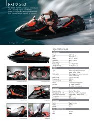
GETTING UNDERWAYTo WearThe operator and passenger(s) mustwear a Coast Guard approved PersonalFlotation Device (PFD) that is suitablefor PWC use.An operator and the watercraft’s passenger(s)should have ready accessto shatterproof glasses should ridingconditions or personal preference warrant.Wind, water spray and speedmay cause a person’s eyestowaterandcreateblurredvision.The operator and passenger(s) ofPWCs must wear protective clothing,including:– a wet suit bottom or thick, tightlywoven, snug fitting clothingthat provides equivalent protection.Thin bike shorts for examplewould not be appropriate. Severeinternal injuries can occur if wateris forced into body cavities as aresult of falling into water or beingnear jet thrust nozzle. Normalswimwear does not adequatelyprotect against forceful water entryinto the lower body opening(s) ofmales or females.– footwear, gloves and goggles/glasses are also recommended.Some type of lightweight, flexiblefoot protection is recommended.This will help reduce possible injury,should you step on sharp underwaterobjects.10 ___________ SAFETY INFORMATION ___________
Eye protectionVest-type personalflotation deviceGlovesWet suit orwet suit bottomFootprotectionF00A12L____________ SAFETY INFORMATION ___________ 11
HelmetsSome Important ConsiderationsHelmets are designed to offer somedegree of protection in case of impactto the head. In most motorizedsports, the benefits of wearing a helmetclearly outweigh the drawbacks.However, in the case of motorized watersportssuch as riding personal watercraft,this is not necessarily true asthere are some particular risks associatedwith the water.BenefitsA helmet helps to reduce the risk ofinjury in case of a head impact againsta hard surface such as another craft,for example, in the case of a collision.Similarly, a helmet with a chinguardmight help prevent injuries to the face,jaw, or teeth.RisksOn the other hand, in some situationswhen falling off the watercraft, helmetshave a tendency to catch the water,like a “bucket”, and put severestresses on the neck or spine. Thiscould result in choking, severe or permanentneck or spine injury, or death.Helmets may also interfere with peripheralvision and hearing, or increasefatigue, which could contribute to increasethe risk of a collision.Weighing the Risks vs BenefitsIn order to decide whether or not youshould wear a helmet, it is best to considerthe particular environment youwill be riding in, as well as other factorssuch as personal experience. Willthere be a lot of traffic on the water?What is your riding style?The Bottom LineSince each option minimizes somerisks, but increases others, beforeeach ride you must decide whether towear a helmet or not based on yourparticular situation.If you decide to wear a helmet, youmust then decide what type is themost appropriate for the circumstances.Look for helmets that meetDOT or Snell standards, and if possible,choose one designed for motorizedwatersports.RacingDue to the nature of competition andthe proximity of other crafts, BRP recommendswearing a helmet in closequarter PWC racing activities. Alwaysfollow the helmet requirements of thesanctioning organization.To BringAlways carry the regulatory safetyitems and have them convenientlyon board available for use. Checkthe local regulations or consult yourauthorized <strong>Sea</strong>-<strong>Doo</strong> dealer. Such requiredsafety items usually include,without limitation, a sound signalingdevice such as a whistle, a watertightflashlight or approved flares, a buoyantheaving line, an anchor and rope*,a bailer*, and an appropriate fire extinguisher*.The items marked witha “*” are not required in Canada if allpersons on board a PWC are wearingaPFD.A cellular telephone in a waterproofbag or container has also been foundto be beneficial to boaters when in distressor just for contacting someoneon shore.12 ___________ SAFETY INFORMATION ___________
To DoRead and understand all <strong>warning</strong>/cautionlabels on your <strong>Sea</strong>-<strong>Doo</strong> PWC,your Operator’s Guide, all other safetydocuments, and watch properly yourSafety Videocassette, before operating.Always keep in mind that the““ symbol, the Warning symbol,identifies an instruction which, if notfollowed, may cause serious personalinjuries including the possibility ofdeath.Check local and federal boating lawsapplicable to the waterways whereyou intend to use your watercraft.Learn the local rules of the road.Know and understand the applicablenavigation system (such as buoys andsigns).Knowthewatersinwhichthewatercraftis to be operated. Current, tides,rapids, hidden obstacles, wakes andwaves etc. can affect safe operation.It is not advisable to operate the watercraftin rough or inclement weather.For safety reasons and proper care,always perform “Daily PreoperationChecks” as specified in your Operator’sGuide before operating yourwatercraft.Keep the engine shut-off cord (safetylanyard) attached to the operator’sPFD at all times and keep it free fromhandlebars so that engine stops if operatorfalls off. After riding, removecord from PWC to avoid unauthorizeduse by children or others. If operatorfalls off the watercraft and safety lanyardis unattached, the watercraft willnot stop.____________ SAFETY INFORMATION ___________ 13
OPERATIONCollision AvoidanceDo not release throttle when trying tosteer away from objects. You needthrottle to steer.Always keep a constant lookout forother water users, other boats or objects,especially when turning. Bealert for conditions that may limit yourvisibility or block your vision of others.Respect the rights of other recreationistsand/or bystanders and alwayskeep a safe distance from all othercraft, people and objects.Do not wake or wave jump, ride thesurf line or attempt to spray or splashothers with your watercraft. You maymisjudge the ability of the watercraftor your own riding skills and strike aboat or person.This watercraft has the capability ofturning more sharply than other boats,however, unless in an emergency, donot negotiate sharp, high speed turns.Such maneuvers make it hard for othersto avoid you or understand whereyou are going. Also, you and/or yourpassenger(s) could be thrown fromthe watercraft.Like any other craft, this PWC has nobrake. Stopping distance will vary dependingon initial speed, load, wind,and water conditions. Practice stoppingand docking in a safe, traffic freearea to have an idea of how long it willtake to stop the watercraft under varyingconditions.Maintaining or increasing speed maybe necessary to avoid a collision.Safe RidingAlways keep in mind that as the throttlelever is released to idle position,less directional control is available, andas the engine is off, directional controlis lost. You need throttle to steer.Ride within your limits and level ofriding ability. Avoid aggressive maneuversto reduce the risk of loss ofcontrol, ejection and collision. Understandand respect the performance oryour watercraft.Always ride responsibly and safely.Use common sense and courtesy.While your watercraft has the capacityof operating at high speeds, itis strongly recommended that highspeed operation only be applied whenideal conditions exist and are permitted.Higher speed operation requiresa higher degree of skill and increasesthe risk of severe injuries.The forces generated on the bodyof riders while turning, negotiatingwaves or wakes, operating in choppywaters, or falling off the watercraft,especially at higher speeds, maycause injury including the possibility ofbroken legs and other bones or moreserious injuries. Remain flexible andavoid sharp turns.In shallow water, proceed with cautionand at very low speeds. Groundingor abrupt stops may result in injury.Debrismayalsobepickedupandbethrown rearward by the jet pump ontopeople or property.Do not use the watercraft’s reverse, ifso equipped, to stop. You or your passenger(s)could be violently ejectedforward onto the handlebars or evenoff the watercraft onto the hazard.PWCs are not designed for night-timeoperation.14 ___________ SAFETY INFORMATION ___________
Operator/PassengerAwarenessThe watercraft operator has the responsibilityto inform passenger(s) ofsafety measures.Never turn handlebar while someoneis nearby rear of watercraft. Keepaway from steering moving parts(nozzle, side vanes, linkage, etc.).Do not start or operate the watercraftif anyone is seated on the sun deck,if so equipped, or swim platform, or isnearby in the water. Water and/or debrisexiting jet thrust nozzle can causesevere injury.The operator and passenger(s) shouldbe properly seated before starting ormoving the watercraft, and at all timeswhen watercraft is in motion. All passenger(s)should be instructed to usethe handholds or seat straps provided,or in the alternative on a PWC, tohold the waist of the person in front ofthem.When accelerating on a PWC with apassenger(s), whether from a completestop or while underway, alwaysdo so progressively. Fast accelerationmay cause your passenger(s) to loosetheir balance or grip and fall rearwardoff the watercraft. Make sure thatyour passenger(s) know of, or anticipate,any rapid acceleration.Keep away from intake grate while engineis on. Items such as long hair,loose clothing, or PFD straps can becomeentangled in moving parts resultingin severe injury or drowning.To prevent accidental starting, alwaysdetach the safety lanyard from the watercraftwhen swimmers are boardingor nearby, or during removal of anyweeds or debris from the intake grate.It should be remembered that sun,wind, alcohol, drugs, fatigue and illness,may impair your judgement andreaction time.On a PWC, never place your feet andlegs in the water to aid turning.Manoeuvrability of theWatercraft/TowingDo not overload the watercraft or takeon more passengers than designatedfor the particular watercraft. Overloadingcan affect maneuverability,stability and performance.Avoid adding on accessories, or equipmentwhich may alter your control ofthe watercraft.The watercraft may be fitted with toweyelets which can be used to attach aski rope.Riding with a passenger(s) or pullinga tube, skier or wakeboarder makesthe watercraft handle differently andrequires greater skill.Always respect the safety and comfortof your passenger(s) and person beingtowed on skis, wakeboard or otherwater products.Always carry an observer when pullinga tube, skier or wakeboarder, proceedwith only as much speed as requiredand follow the observer’s instructions.Unless absolutely necessary, do notmake tight, sharp turns. Keep a safedistance from the docks, other swimmers,craft or objects.Use a tow rope of sufficient lengthand size and make sure it is adequatelysecured to your watercraft. Whilesome craft are equipped or can be fittedwith a specially designed towingmechanism avoid installing a tow poleon a PWC. It can become a hazardshould someone fall on it.Be advised that serious injury can resultif the tow rope becomes slack duringa tight turn or when circling. Therope could become wrapped aroundthe neck or limbs of a person that hasfallen in the water.____________ SAFETY INFORMATION ___________ 15
With wakeboard and/or rack installed,operate with extra caution: never performagressive maneuvers includingspin-out; never jump waves; use commonsense and limit speed. Otherwise,wakeboard could detach or occupantscould fall off and get injuredagainst the wakeboard or rack.Don’t forget: Ride smart from thestart and we all win!16 ___________ SAFETY INFORMATION ___________
OPERATING RULESOperating a watercraft can be comparedwith driving unmarked highwaysand roads. To prevent collisionsor avoid other boaters, a system ofoperating rules must be followed. It’snot only common sense... it’s thelaw!Remember these Rulesof the RoadKnow the Right of Way RulesGenerally keep to your right and safelyavoid other craft by keeping a safedistance from other craft, people andobjects.Meeting Head-OnKeep right.F00A15YPassingGive right of way to other craft andkeep clear.PortBowStarboard12F00A16AF00A13YStern1. RED light2. GREEN light (yield zone)CrossingGive right of way to craft ahead andto your right. Never cross in front of aboat;Navigation SystemNavigational aids, such as signs orbuoys, can assist you identify safewaters. Buoys will indicate whetheryou should keep to the right (starboard)or to the left (port) of the buoyor to which channel you can continue.They may also indicate whether youare entering a restricted or controlledarea such as a no wake or speed zone.They may also indicate hazards or pertinentboating information. Markersmaybe located on shore or on thewater. They can also indicate speedlimits, no power craft or boating, anchorageand other useful information.(The shape of each type of marker willprovide assistance).Make sure you know and understandthe navigation system applicable tothe waterways where you intend touse the watercraft.F00A14Y____________ SAFETY INFORMATION ___________ 17
WATERSKIING SIGNALSFor your information, here are the most commonly used waterskiing signals.SlowerStopFasterOKTurn rightBack to dockSpeed OKTurn leftF00A17LFallen skier — Watch out18 ___________ SAFETY INFORMATION ___________
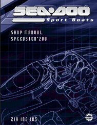
LOCATION OF THE IMPORTANT LABELSThe following labels are on your watercraft. If missing or damaged, they can bereplaced free of charge. See an authorized <strong>Sea</strong>-<strong>Doo</strong> dealer.Please read the following labels carefully before operating this watercraft.6-15 1 7-9-103-5-13178 11 2-412-14F18L03KTYPICAL____________ SAFETY INFORMATION ___________ 21
Label 1F12L0FLSOME MODELS22 ___________ SAFETY INFORMATION ___________
Label 1 (cont'd)F16L0PLSOME MODELS____________ SAFETY INFORMATION ___________ 23
Label 1 (cont'd)F18A06LSOME MODELSLabel 2F22L3GL24 ___________ SAFETY INFORMATION ___________
Label 3Label 7F00A2QYWARNING / AVERTISSEMENTPRESSURIZED FUELDo not unscrew protective cap. Must be used onlyby Bombardier certified technician. Do not operate thewatercraft without cap properly installed.ESSENCE SOUS PRESSIONNe pas dévisser le capuchon protecteur.Réservé seulement à l’usage d’un technicien certifiépar Bombardier. Ne pas opérer la motomarine sansle capuchon bien installé.F22A0AYLabel 8Label 4F00A23YLabel 5F00L2YYSOME MODELSLabel 9F00A26YSOME MODELSLabel 6F18L0NYLabel 10F00A27YF18L10Y____________ SAFETY INFORMATION ___________ 25
902Label 11Label 12F18L0YYA01A2EYLabel 13219218F00A2SLSOME MODELS26 ___________ SAFETY INFORMATION ___________
Label 14F22A09LLabel 15Label 16F18L31YSOME MODELSF00A2TY____________ SAFETY INFORMATION ___________ 27
Label 17F18L3KYSOME MODELS28 ___________ SAFETY INFORMATION ___________
VEHICLEINFORMATION_____________________ 29
REGISTRATION NUMBER LOCATIONAll personal watercraft are required by federal law to be registered and legallynumbered.Due to space availability for proper display of registration number, refer to followingillustration for location. The registration number should appear on each sideof the watercraft. On applicable models install registration number to the left ofthe star label.F18L01L 11. Registration number locationNOTE: The registration number must be above the water line. Ensure also thatthe numbers are of the correct size and color. Check with local applicable regulations.30 ______________________
IDENTIFICATION NUMBERSThe main components of the watercraft(engine and hull) are identifiedby different serial numbers. It maysometimes become necessary to locatethese numbers for warranty purposesor to trace the watercraft in theevent of theft.HullThe Hull Identification Number (H.I.N.)is located on footboard at the rear ofwatercraft.EngineNOTE: Refer to SPECIFICATIONSsection to find what engine is used oneach model.The Engine Identification Number(E.I.N.) is located on the front end ofthe engine.1F18L07Y 11. Hull Identification Number (H.I.N.)It is composed of 12 digits:F18D03YTYPICAL1. Engine Identification Number (E.I.N.)Z Z N 1 2 3 4 5 L 4 9 5F00A0CZSerialnumber*ManufacturerModel yearYear of productionMonth of production*A letter may also be used as a digit._____________________ 31
CONTROLS/INSTRUMENTS/EQUIPMENTSNOTE: Some components do not apply or are optional on some models.All GTX 4-TEC/Wake/RXT except RXP Models13 12 14 11 17 19 15 1921 26-272823361622-39 34-35 252329303132433637-38892216232410F18L0PMTYPICAL32 ______________________
RXP Models13141237-38-396 251720192123-29-3031-32153435262723362491678334253110F19L04L_____________________ 33
1. Safety Lanyard (engine cut-offcord)2. Handlebar3. Throttle Lever4. Engine Start/Stop Button5. Variable Trim System (VTS) Button6. Shift Lever7. Speedometer8. Tachometer9. Information Center Gauge/Buttons10.Glove Box11.GPS (Global Positioning system)receiver12.Fuel Tank Cap13.Front Storage Compartment Cover14.Front Storage Compartment CoverLatch15.Tool Kit16.Air Intake Opening17.<strong>Sea</strong>t Strap18.<strong>Sea</strong>t Extension Latch19.<strong>Sea</strong>t Latch20.<strong>Sea</strong>t Cover21.Rear Grab Handle22.Rear Storage Basket23.Front and Rear (bow/stern) Eyelets24.Mooring Cleats25.Footboard26.Boarding Pads27.Boarding Platform28.Boarding Step29.Flushing Connector30.Bilge Drain Plugs31.Jet Pump Nozzle32.Reverse Gate33.Jet Pump Water Intake34.Fuses35.Battery36.Side Vanes37.Engine Oil Dipstick38.Engine Oil Filling Cap39.Cooling System Expansion TankCap40.Ski/Wakeboard Post41.Wakeboard Rack34 ______________________
CONTROLS/INSTRUMENTS/EQUIPMENTSFUNCTIONS1) Safety Lanyard(engine cut-off cord)The safety lanyard cap should be securelysnapped onto its post to be fullyoperational.Pulling the safety lanyard cap from itspost stops the engine operation. WARNINGWhile engine can be stopped usingthe engine start/stop button,good habits recommend that thesafety lanyard also be disconnectedwhen stopping.Attach the safety lanyard to the operator'sPersonal Flotation Device (PFD)andsnapthecaptotheposttobeableto start the engine.Two short beeps indicates the systemis ready to allow engine starting.Otherwise, refer to the TROU-BLESHOOTING section for the codedsignals chart.F18L0QY 11. Safety lanyard cap on the post2. Safety lanyard secured on operator's PFD2 WARNINGShould the engine be stopped,watercraft directional control is reduced.Always disconnect safetylanyard when watercraft is not inoperation in order to prevent accidentalengine starting or to avoidunauthorized use by children orothers or theft.If engine is not started within 5 secondsafter installing the safety lanyardon its post, 4 very short beeps every 3second interval will sound for approximately4 hours to remind you to startthe engine or to remove safety lanyard.Afterwards, the beeps will stop.The same will occur when safety lanyardis left on its post 5 seconds afterengine is stopped.Always ensure safety lanyard is notleft on its post after engine is stopped.IMPORTANT: Leaving the safety lanyardon its post when engine is notrunning will slowly discharge the battery.Digitally Encoded SecuritySystem (DESS)The safety lanyard cap specifically containsan electronic circuit that gives it aunique electronic serial number. Thisis the equivalent of a conventional key.This safety lanyard cannot be used onanother watercraft and conversely, theone from another watercraft cannot beused on your watercraft.However, the DESS brings a great flexibility.You can buy an additional safetylanyard and have it programmed foryour watercraft.To have additional safety lanyard, referto an authorized <strong>Sea</strong>-<strong>Doo</strong> dealer._____________________ 35
Limited-Speed OperationThe 4-TEC models also offers a specialsafety lanyard -- the SEA-DOO LearningKey TM -- which electronically limitsthe speed of the watercraft to approximately55 km/h (35 MPH) thereforeenabling first time users and lessexperienced operators to learn how tooperate the watercraft while gainingthe necessary confidence and control.F18K18YTYPICAL1. Adjustment knob3) Throttle LeverWhen the throttle lever is squeezed,the watercraft accelerates. Whenfully released, engine automaticallyslows down to idle speed and watercraftis gradually stopped by waterdrag.1F00L2SY2) HandlebarThe handlebar controls the direction ofthe watercraft. Turning the handlebarto the right steers the watercraft to theright and inversely. WARNINGCheck handlebar and correspondingsteering nozzle and side vanesoperation before starting. Neverturn handlebar while someone isnearby rear of watercraft. Keepaway from steering moving parts(nozzle, side vanes, linkage etc.).4) Engine Start/StopButtonTo start engine, depress and hold thestart/stop button. Release immediatelyafter engine is started.To stop engine, depress the start/stopbutton. When stopped, disconnectsafety lanyard from the post.It issuggested to release throttle leverfirst. WARNINGDirectional control is reducedwhen the throttle is released orwhen engine is off.Adjustment (if so equipped)The handlebar height can be adjustedto suit rider preferences.To perform this adjustment, turn theknob underneath the handlebar.36 ______________________
16) Shift LeverA push-pull lever:– forward– neutral– reverse. WARNINGShift lever should only be usedwhen the engine is idling and watercraftis completely stopped. Donot use as a grab handle.F18L09Y1. Engine start/stop button5) Variable TrimSystem (VTS) Button(if so equipped)Located just below the enginestart/stop button, this button is usedto change pump jet nozzle positionand to adjust ride to suit watercraftload and water conditions.1 WARNINGOnly use reverse at slow speedand for the shortest time possible.Always ensure the path behindis clear of objects and personsincluding children playing in shallowwater.CAUTION: Never rev the engine athigh RPM in reverse.From the forward position, pull thelever to reverse. Push back to go toforward. Always set in forward whenfinished. To find the neutral, set in reversethen push back until the watercraftstops moving backwards.F19L01Y1. VTS buttonA VTS position indicator is included inthe information center gauge. See IN-FORMATION CENTER in this section.F18J01Y11. Forward position_____________________ 37
9) Information CenterGauge/ButtonsThis is a multifunction gauge that suppliesseveral real time useful informationto the driver.Components Description1 2F18J02Y 11. Neutral positionF18H08Y 3TYPICAL1. Analog speedometer2. Analog tachometer3. Display areaF18J03Y 11. Reverse position7) SpeedometerAnalog speedometer indicates thespeed of watercraft in miles per hour(MPH) and kilometers per hour (km/h).In addition, a digital speedometer canbe displayed in the information center.See INFORMATION CENTER GAUGE/BUTTONS below.The speed sensor mounted on thetransom sends the signal to theMPEM and the MPEM send it tothe gauge.F18H08Z 1TYPICAL1. Text and numerical area8) TachometerAn analog tachometer indicates therevolutions per minute (RPM) of theengine. Multiply by 1000 to obtain theactual revolutions.38 ______________________
F18L09011. Function buttonsDisplay AreaThe display area comprises the following.2F19L09Y 1 3 41. Fuel level indicator2. Numerical section3. Units and messages section4. VTS position indicator (if so equipped)Fuel Level DisplayBar gauge continuously indicates theamount of fuel in the fuel tank whileriding. A low-fuel condition is also indicatedon the information center asonly one bar is displayed. See MES-SAGE DISPLAY below.Numerical SectionThis section shows the digits ofthe function displayed such as thespeedometer, trip hour meter etc.Units and Messages SectionThis section shows the units relatedto the numbers displayed. Units suchas KMH (MPH), HOUR etc. are displayed.This section also display navigationaland system fault informations.See the gauge functions and messagelists below for more details.Gauge FunctionsDigital Tachometer: Indicates therevolution per minute (RPM) of theengine.Digital Speedometer: Indicates thespeed of the watercraft in miles perhour (MPH) and kilometers per hour(km/h).Depth Gauge (if so equipped): It continuouslydisplay the water depth underthe hull within 0 to 50 meters (0 to170 feet).NOTE: Under certain conditions,the gauge may stop displaying. Thegauge ability to display the depth dependson the usage conditions. WARNINGNever use the depth gauge as a<strong>warning</strong> device to ride in shallowwater. Use it as a navigation guideonly. Not to be used for navigationpurposes.Compass (if so equipped):Displaysthe cardinal points to indicate the orientationof the watercraft. WARNINGUse the compass as a guide only.Not to be used for navigation purposes.Average Speed: The informationcenter approximately calculates anddisplays the average speed (AV KM/Hor AV MPH) of the watercraft sincethe last engine start._____________________ 39
Distance: (KM or MILES) The informationcenter approximately calculatesthe distance based on the operationtime and the watercraft speedand displays the result in kilometers(KM) or miles (MILES).Hourmeter: Displays the time inhours of the watercraft usage (HOUR).Water Temperature: Displays thewater temperature of the water surface(L TEMP) in degrees Celsius (°C)or Fahrenheit (°F).Exterior Temperature (if soequipped): Displays the exterior airtemperature (E TEMP) in degrees Celsius(°C) or Fahrenheit (°F).Trip Hour Meter: (TRIPMTR) Allowsto measure an interval of time in hoursand minutes (hh:mm).VTS Position Indicator(if so equipped)The VTS position indicator shows theriding attitude of the watercraft.2F18L09Z 1 21. To change display mode2. To set or reset a functionResetting a FunctionTo reset a function (such as the triphour meter, distance, etc.) press andhold the SET button for 2 secondswhile in the appropriate mode.Display SelectionRepeatedly pressing the MODE buttonscrolls the following displays:Compass, tachometer, speedometer,average speed, distance, hourmeter,water temperature, exterior temperature(if so equipped), depth gauge (ifso equipped), and trip hour meter.F19L0AY11. Position indicator2. Bow up3. Bow downFunction ButtonsDifferent displays and functions canbe activated using 2 buttons — MODEand SET — following specific sequencesas described below.3F18L09111. Press to change display mode40 ______________________
When you are satisfied with yourchoice, stop pressing the button andit will become active. The displayyou have chosen will remain until it ischanged.Display PrioritiesAs a self test at start-up, the needlesof the speedometer and tachometerwill sweep to their maximum position,all LCD segments and the LED willturn on for 3 seconds each time theinformation center is activated (whensafety lanyard is installed). This allowsthe driver to validate they are all workingproperly.When the information center is activated,the last function set will be displayed.In the event of a <strong>warning</strong> message,the message will blink and overridethe units display unless MODE buttonis pressed. The display will then displaythe last function after 10 seconds.If more than one <strong>warning</strong> message occurs,the blinking messages will scrollevery 4 seconds.Other FunctionsThe following describes how to selectother available functions.Language OptionWhile in the compass mode:F18L09111. Repeatedly pressF18L0921. Press to end1English/Metric SystemAllows to display the units in the metricsystem or in the SAE English system.NOTE: This function is not availablewhen information center displays thecompass, hourmeter or trip hour meter.F18L0921. Press and hold for 2 seconds1_____________________ 41
Trip hour meter is reset every time engineis turned off.F18L09011. Press TOGETHER and hold for 2 secondsTrip Hour MeterWhile in the trip hour meter mode:F18L09211. Press to start or stop trip hour meterF18L09211. Press and hold for 2 seconds to resetMessage DisplayThe information center features adisplay area that blinks a messagewhenever one of the following circumstancesoccurs. The abbreviationsbetween parenthesis here arethe code displayed:– engine or exhaust system overheating(H-TEMP)– low oil pressure (OIL)– low battery voltage (12V LOW)– high battery voltage (12V HI)– low fuel level (FUEL-LO)– maintenance reminder (MAINT)– check engine (CHK ENG)– sensor failure (vehicle electronicequipment) (SENSOR)– invalid safety lanyard (KEY)– safety lanyard, learning key active(L KEY)– end of faults (END).A beeper will sound depending on thefault occurring to catch the driver attentionwhen necessary.Except for low liquid levels, which canbe corrected by refilling, it is recommendedto see an authorized <strong>Sea</strong>-<strong>Doo</strong>dealer when other messages occur.NOTE: If a fault occurs, this systemgenerates numbered fault codes(P-XXXX) that can be displayedthrough the information center usinga special procedure. In case of afailure, you may call your authorized<strong>Sea</strong>-<strong>Doo</strong> dealer and he would be ableto assist you to have the codes displayedto help troubleshooting.Warning LightThe red <strong>warning</strong> LED (Light-EmittingDiode) blinks along with the beeper tocatch your attention.42 ______________________
Maintenance InformationWhen the watercraft is due for amaintenance inspection, the messageMAINT will blink. Afterwards, itwill blink at every start-up for 10 seconds.After servicing, your authorized<strong>Sea</strong>-<strong>Doo</strong> dealer will clear it.10) Glove BoxA small, convenient storage compartmentfor personal articles.11) GPS Receiver (Globalpositioning system)(if so equipped)A removable GPS receiver located onthe glove box cover.The GPS receiver provides the watercraftposition on earth.Refer to manufacturer's documentationsupplied with the GPS receiver forproper use. WARNINGReading the GPS receiver can distractfrom the operation of thewatercraft, particularly from constantlyscanning the environment.This could lead to a collision resultingin severe injuries or death.Before reading the GPS receiver,ensure your environment is clearand free from obstacle, and bringthe watercraft to a low speed.Additionally, make sure to oftendouble-check for obstacles. WARNINGRemember, the data provided bythe GPS receiver is for referenceonly. NEVER rely solely on this informationfor your safety.CAUTION: To prevent weatherdamage or theft to your GPS receiver,always remove it from itsreceptacle when leaving the watercraft.PushreleasebuttontoremoveGPSreceiver.F19L05YTo reinstall, position GPS receiver in itsreceptacle and push until it latches.F19L06Y12) Fuel Tank CapOpen the front storage compartmentcover to expose fuel tank cap.F18F01Y 1TYPICAL1. Fuel tank capRefer to the vehicle illustration for fueltank cap location._____________________ 43
Unscrew the cap counterclockwise.After fueling, reinstall cap and fullytighten. WARNINGAlwaysstoptheenginebeforerefueling.Fuel is flammable and explosiveunder certain conditions.Always work in a well ventilatedarea. Do not smoke or allow openflames or sparks in the vicinity. Fueltank may be pressurized, turncap slowly when opening. Neveruse an open flame to check fuellevel. When fueling, keep watercraftlevel. Do not overfill or topoff the fuel tank and leave watercraftin the sun. As temperatureincreases, fuel expands and mightoverflow. Always wipe off any fuelspillage from the watercraft. Periodicallyverify fuel system. Alwaysturn the fuel tank valve (ifso equipped) to OFF position whenthe watercraft is not in use.All Models13) Front StorageCompartment CoverIt gives access to the front storagecompartment. Always relatch coverafter closing.Front Storage CompartmentA convenient watertight area (removablebasket on some models) to carrypersonal articles. Ideal location fortowrope, first aid kit, etc. WARNINGNever leave any heavy or breakableobjects loose in the storagearea/basket. Never operate thewatercraft with any storage compartmentcover open.RXP Models WARNINGNever store or carry anything belowbasket.All Models except RXPIf there is water in the storage area,pull out the drain plug to let water goout. Reinstall the plug when done.F18L0KY 11. Drain plugNOTE: The water will flow to thebilge. If there is an important quantityof water, ensure to drain the bilge(out of water) prior to using the watercraft.The front storage area includes a latchto hold an approved fire extinguisher(sold separately).F18L0LY1. Retaining straps2. Extinguisher (sold separately)1244 ______________________
WARNINGEnsure to properly secure extinguisherwith the supplied retainingstraps.Some models feature a removablebasket. Its handle is convenient tocarry personal objects.F18L2YY1TYPICAL1. Removable basketSome models may have convenientrubber bands and other useful accessories.RXP ModelsLift the basket to get access to theholder for an approved fire extinguisher(sold separately). It also containsthe Operator’s Guide and the tool kit.F19L0BY14) Front StorageCompartment CoverLatchPullthelatchleverupwardinordertoopen the front storage compartmentcover. Always relatch.NOTE: Verify periodically the lock pintightness of storage cover. Tighten ifneeded and make sure storage coverlatches properly.15) Tool KitThe tool kit contains tools neededto perform basic watercraft maintenance.All Models except RXPIt is located under the seat extension,1F18L0WY 21. <strong>Sea</strong>t extension2. Tool kitRXP ModelsIt is located in the front storage compartmentinside the holder for the fireextinguisher. See FRONT STORAGECOMPARTMENT above.All Models except RXP16) Air Intake OpeningThis is where air enters to supply theengine and to ventilate the enginecompartment. If the air intake openingis kept under water, water will getinside bilge._____________________ 45
CAUTION: If the air intake openingis kept under water, such as turningconstantly in tight circles, water willget inside bilge, which may causesevere damage to internal parts ofthe engine.17) <strong>Sea</strong>t StrapThe seat strap provides a handhold toassist boarding and is used as a handholdfor the passenger.RXP ModelsThe seat strap is available when theseat cover is removed.18) <strong>Sea</strong>t Extension Latch(if so equipped)Removing the seat extension allowsaccess to the rear storage basket. Italso gives access to the seat latch.2F18L0CY1. <strong>Sea</strong>t latchTo remove seat, pull the latch leverupward and hold. Lift and pull the seatrearward.NOTE: It is necessary to remove theseat extension first.Tolatchseat,alignlatchholewithpinthen, firmly push down on the rearportion of the seat.11F18L0FZ1. <strong>Sea</strong>t extension latch2. Rear grab handle19) <strong>Sea</strong>t LatchRemoving the seat allows access tothe engine compartment.The seat latch is located at the rear endand underneath the seat.F00L2TY 1 21. Latch hole2. Pin46 ______________________
Engine CompartmentRemoving the seat gives access to theengine, electrical and fuel systems. WARNINGCertain components in the enginecompartment may be very hot.Direct contact may result in skinburn. When starting or operatingthe engine, do not touch any electricalpart. Never leave any object,rag, tool, etc., in the engine compartmentor in the bilge.20) <strong>Sea</strong>t Cover(if so equipped) WARNINGNever sit on the seat cover.The seat cover allows one to install anumber on its side panels. It is removableto expose the seat for a passenger.To remove cover:Unlatch and pull seat out.Unlock the quarter-turn screws.Position rear of cover in place withoutinserting front tabs yet.Carefully pull tabs outward each sideof seat and insert cover in place.F19L08YFinish pushing cover in position thenlock the quarter-turn screws.Install seat and properly relatch.21) Rear Grab HandleProvides a handhold for boardingwhen needed and a handhold forthe passenger or the spotter. Seeillustration above.CAUTION: Never use the grab handleto tow anything or to lift the watercraft.22) Rear Storage Basket(if so equipped)A convenient watertight, removablebasket to carry personal articles.F19L07YPull cover tabs each side of seatthenremove cove.Install seat and properly relatch.To reinstall cover:Unlatch and pull seat out.F18L0GY11. Rear storage basket_____________________ 47
Spare Spark Plug HolderThe storage basket features a sparespark plug holder.To keep spare spark plugs dry and preventshocks that might affect the adjustmentor break them, a holder isprovided.Unscrew cap counterclockwise to exposethe holder and insert spark plugin their holes. Reinstall cap.2 1F00L0EY1. Front (bow) eyeletRear (stern) EyeletAll Models except RXPThis eyelet allows a rope with a hook,a closed end or an open end to beattached.1F18L0HY 31. Storage basket2. Spare spark plug holder cap3. Spark plug holderNOTE: Adjust spare spark plug gapaccording to SPECIFICATIONS beforeinstallation.NOTE: Spare spark plugs are not suppliedwith the watercraft.23) Front and Rear(bow/stern) EyeletsF18L0RY1. Rear (stern) eyelet1Front (bow) EyeletEyelets can be used for mooring, towingand as a tie-down point during trailering.48 ______________________
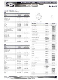
RXP Models3 eyelets are available for your convenience.27) Boarding PlatformProvides a large surface for easierboarding from rear of watercraft.28) Boarding Step(if so equipped)A convenient step to help reboardingthe watercraft.1F19L0CY 11. EyeletsAll Models24) Mooring CleatsThese cleats can be temporarily usedfor docking, while refueling for example.F18L0IY1. Boarding stepPull down the step with your hand andhold until a foot or a knee is put on thestep.F18L0SY 1TYPICAL1. Mooring cleatsCAUTION: Never use mooringcleats to pull or lift the watercraft.25) FootboardUser's feet should rest on the footboardwhen riding.26) Boarding PadsProvide a cushioned surface for theknees when boarding from rear of watercraft.F18L0JY29) Flushing ConnectorA convenient connector is providedto allow easy installation of a gardenhose to flush the exhaust cooling system._____________________ 49
WARNINGWhen operating the engine whilethe watercraft is out of the water,theheatexchangerintherideplatemay become very hot. Avoid anycontact with ride plate as burnsmay occur.On some models, an additional flushingconnector is located in enginecompartment to allow flushing whilewatercraft is on a lift or if you prefer toflush from this location, either flushingconnector can be used to flushthe exhaust cooling system. Removeseat to gain access.2F18L0TYALL MODELS EXCEPT RXP1F18E1TY1SOME MODELS1. Flushing connector2. Dust capRefer to POST-OPERATION CAREsection for proper use.F19J01YRXP MODELS1. Flushing connector30) Bilge Drain PlugsShould water be found in the bilge, itcan be easily drained by unscrewingthe drain plugs when engine is off andwatercraft is out of water.CAUTION: Remove watercraftfrom water prior to unscrewingdrain plugs.50 ______________________
1 1F18L14YTYPICAL1. Drain plugs2. Tighten3. Unscrew2 3Tilt the watercraft slightly to the rearso that the water can completely flowout of the bilge.It is suggested to drain bilge on aramp.CAUTION: Make sure drain plugsare properly secured prior tolaunching the watercraft in water.31) Jet Pump NozzleJet pump nozzle turns side to side viarider input at the handlebar. This providesdirectional control when engineis running.F18J05Z 1TYPICAL1. Jet pump nozzle32) Reverse GateWhen selecting the neutral or reverseposition with the shift lever, the reversegate moves up or down to obtainthe desired position.F18J05Y 1TYPICAL1. Reverse gate33) Jet Pump Water Intakeand Ride PlateThe water is drawn up by the impellerthrough this opening. The water intakegrate minimizes the entry of foreignobjects into the propulsion system.NOTE: The ride plate is the heat exchangerfor the ENGINE cooling system._____________________ 51
WARNINGKeep away from intake grate whileengine is on. Items such as longhair, loose clothing or personalflotation device straps can becomeentangledinmovingpartsresultingin severe injury or drowning.1F18H0JYF18J04Y 1 2TYPICAL1. Water intake2. Ride plate WARNINGWhen operating the engine whilethe watercraft is out of the water,theheatexchangerintherideplatemay become very hot. Avoid anycontact with ride plate as burnsmay occur.34) FusesAll Models except RXPFuses are located under the seat inthe bilge. Refer to MAINTENANCE formore details.TYPICAL1. FusesRXP ModelsFuses are located under basket infront storage compartment. Refer toMAINTENANCE for more details.F19H01Z1. Fuses152 ______________________
35) BatteryAll Models except RXPBattery is located under seat in bilge.Refer to SPECIAL PROCEDURES.F18H0AYTYPICAL1. BatteryRXP ModelsBattery is located under basket in frontstorage compartment. Refer to SPE-CIAL PROCEDURES.11Models with Sliding Side VanesWhen engine RPM is reduced, theside vanes are lowered to assist thesteering system. Refer to PRINCI-PLE OF OPERATION in OPERATINGINSTRUCTIONS section for the descriptionof the system.All Models WARNINGCheck handlebar and correspondingside vanes operation beforestarting. Never use side vanes asa supporting point to board thewatercraft or to lift it. Never turnhandlebar while someone is nearbyrear of watercraft. Keep awayfrom steering moving parts (nozzle,side vanes, linkage etc.).37) Engine Oil DipstickLocated in engine compartment, onthe engine. It indicates the engine oillevel. WARNINGCertain components in the enginecompartment may be very hot.Direct contact may result in skinburn.F19H02Y1. Battery36) Side VanesSide vanes are part of the Off-PowerAssisted Steering (O.P.A.S. TM )system.The side vanes assist the steering system._____________________ 53
1F18D04YTYPICAL — ALL MODELS EXCEPT RXP1. Oil dipstickF18D09YTYPICAL — ALL MODELS EXCEPT RXP1. Oil filling cap111F19D01YRXP MODELS1. Oil dipstickRefer to LIQUIDS for more details.38) Engine Oil Filling CapLocated in engine compartment, onthe engine. It allows adding oil in theengine when required.F19D01ZRXP MODELS1. Oil filling capRefer to LIQUIDS for more details.39) Cooling SystemExpansion Tank CapLocated in engine compartment. Itprovides access to the expansion tankfilling neck.54 ______________________
WARNINGCertain components in the enginecompartment may be very hot.Direct contact may result in skinburn.To lift post, unlock by pulling the lockingpin then lift post. Ensure it is properlylocked. Lowering the post is theopposite operation.21Remove seat extension and storagebasket to expose expansion tank.F18L2ZY1. Ski/wakeboard post2. Pull locking device to unlockF18E0MY 21ALL MODELS EXCEPT RXP1. Expansion tank2. Cap122 1F19E01YRXP MODELS1. Expansion tank2. CapRefer to LIQUIDS for more details.40) Ski/Wakeboard Post(if so equipped)Pull up the post to hook up a ski orwakeboard rope. Push down whenfinished and lock in properly.F18L30Y1. Ski/wakeboard post lifted2. Ensure it is locked WARNINGMake sure ski/wakeboard post isfully extended and locked beforeuse. Completely retract and lockwhen not used. Use caution withskier/wakeboarder in tow as towrope may backlash to watercraftwhen released. Never perform asharp turn when towing a skier,wakeboarderoranytoy.Always have one person other thanthe operator as an observer._____________________ 55
NOTE: The handles are supplied forthe observer to have a grip whenwatching.CAUTION: Never use the ski/wakeboardpost to tow other crafts.41) Wakeboard Rack(if so equipped)Convenient removable rack(s) to carrywakeboard(s).To install:– Position rack on bumper trim withits centerline in between the bucklereceivers located in the footwellarea.– Position the 2 outer J-hooks of therack so as to grab the fiberglass lipof the hull underneath the bumpertrim.F18L3EY– Tighten the straps by firmly pullingupwards.2°F18L3FY– Double-check that rack is properlyinstalled by giving it a tug.F18L3DY1°– Attach the male buckles onto thebuckle receivers located in thefootwell. WARNINGIf rack is not properly secured onthe watercraft, it could becomeloose and detach unexpectedly,creating a risk of injury to peoplenearby. To avoid:– Ensure straps are in good condition.– Secure rack properly on watercraft.– Periodically check that strapsare tight.56 ______________________
– When installing a wakeboard on therack, position wakeboard fin(s) outwardthen secure bungee cords totightly hold wakeboard. WARNINGTo avoid possible injuries and cutsfrom wakeboard's fin(s), alwaysplace FIN(S) OUTWARDS. WARNINGIf wakeboard is not properly securedon rack, it could becomeloose and detach unexpectedly,creating a risk of injury to peoplenearby. To avoid:– Inspect bungee cords conditionand replace if damaged.– Secure wakeboard properly onrack.– Periodically check that board isproperly attached.1F18L3GY1. Fin outwardF18L3IYNOTE: When wakeboard is removedfrom its rack, secure bungee cords sothat they will not move freely whenriding watercraft.F18L3HY– After installation, pull and pushwakeboard to ensure it is tightlysecured to rack.F18L3JY_____________________ 57
CAUTION: The rack is designed tohold one wakeboard. Do not use tohold more than one wakeboard or totransport ski or any other object. Donot use rack(s) as mooring points orto reboard. WARNINGWith wakeboard and/or rack installed,operate with extra caution:– NEVER perform agressive maneuversincluding spin-out.– NEVER jump waves– Use common sense and limitspeed.Otherwise, wakeboard could detachor occupants could fall off andget injured against the wakeboardor rack. WARNINGWhen trailering the watercraft,NEVER leave a wakeboard installedon the rack. Otherwise,wakeboard fin(s) could cause injuryto bystanders or wakeboardcould fly off on the road. Thebungee cords are under tensionand could spring back and whipsomeone when released. Use caution.Removal is reverse of installation.58 ______________________
LIQUIDSCAUTION: Scrupulously follow theinstructions of this section. Failureto do so may reduce the engine's lifeand/or performance.Fueling Procedure WARNINGFollow these safe boating fuelinginstructions meticulously.Turn off engine.Do not allow anyone to remain on thewatercraft.Tie watercraft securely to the fuelingpier.Have a fire extinguisher close at hand.Do not insert the spout too far in fillerneck.Pour fuel slowly so that air can escapefrom the tank and prevent fuel flowback.Be careful not to spill fuel.Stop filling when the fuel reaches thebottom of filler neck. Do not fill intothe filler tube to prevent fuel spill out.Do not overfill. Fully tighten fuel tankcap. WARNINGAlwaysstoptheenginebeforerefueling.Fuel is flammable and explosiveunder certain conditions.Always work in a well ventilatedarea. Do not smoke or allow openflames or sparks in the vicinity. Fueltank may be pressurized, turncap slowly when opening. Neveruse an open flame to check fuellevel. When fueling, keep watercraftlevel. Do not overfill or topoff the fuel tank and leave watercraftin the sun. As temperatureincreases, fuel expands and mightoverflow. Always wipe off any fuelspillage from the watercraft. Periodicallyverify fuel system. Alwaysturn the fuel tank valve (ifso equipped) to OFF position whenthe watercraft is not in use.Recommended FuelNaturally-Aspirated EnginesUse regular unleaded gasoline withthe following recommended minimumoctane number.LOCATIONInside NorthAmericaOutside NorthAmericaOCTANE NUMBER87 octane(RON + MON)/291 RONAll Supercharged EnginesIt is recommended to use a premiumunleaded gasoline with the followingoctane number for optimum performance.LOCATIONInside NorthAmericaOutside NorthAmericaOCTANE NUMBER91 octane(RON + MON)/295 RON_____________________ 59
As a minimum, regular unleaded gasolinewith the following minimum octanenumber may be used.LOCATIONInside NorthAmericaOutside NorthAmericaOCTANE NUMBER87 octane(RON + MON)/291 RONAll ModelsCAUTION: Never experiment withother fuels or fuel ratios. Never usefuel containing more than 10% alcohol,(ethanol or methanol). Theuse of non-recommended fuel canresult in watercraft performance deteriorationand damage to criticalparts in the fuel system and enginecomponents.Engine OilRecommended OilThis watercraft features a 4-stroke engi<strong>net</strong>hat requires 4-stroke motor oilfor internal engine lubrication. Ensureto respect the following requirements.NA EnginesWatercraft featuring 4-stroke engineswithout superchargers require4-stroke motor oil meeting the requirementsfor API service classificationSL, SJ or SH. Always check the APIservice label on the oil container to besure it includes those letters.The XP-S 10W-40 4-stroke oil (P/N 219700 346) sold by authorized <strong>Sea</strong>-<strong>Doo</strong>dealers meets those requirements.NOTE: A synthetic oil meeting thesame requirements may be used. TheXP-S 5W-40 Synthetic 4-stroke oil (P/N293 600 039) is suitable.All Supercharged EnginesUse the XP-S 10W-40 4-stroke oil(P/N 219 700 346) or an equivalent approvedby BRP. The same oil lubricatesboth the engine and the superchargerclutch. The XP-S 10W-40 4-stroke oil(P/N 219 700 346) has been thoroughlytested to be free of any additivesthat could impair the functionality ofthe supercharger clutch.NOTE: Use of any oil that is not recommendedmay void BRP’s limitedwarranty.CAUTION: NEVER use synthetic oilin these engines. This would impairthe proper operation of the superchargerclutch. Do not add anyadditives to the recommended oil.Beware that oils not recommendedby BRP may contain additives (frictionmodifiers) that may cause inappropriateslippage of the superchargerand eventually lead to prematurewear. For this reason, oilsother than XP-S 10W-40 4-stroke oil(P/N: 219 700 346) or an approvedequivalent are not recommended.All EnginesCAUTION: Never use any 2-strokeengine oil.Oil ViscosityThe same oil is recommended forall seasons and all ambient temperatures.60 ______________________
Oil LevelCAUTION: Check level frequentlyand refill if necessary. Do not overfillit would make the engine smokeand reduce its power. Operating theengine with an improper level mayseverely damage engine. Wipe offany spillage.1F18D04YTYPICAL1. DipstickCheck the oil level as follows:NOTE: Before checking the oil levelon this engine, it is necessary towarm-up engine and to let it idle for 30seconds before shutting it off. Thereafterit is necessary to wait 30 seconds.Then, the oil can be checked.This is required to allow the oil to properlylevel in the different oil chambers.Otherwise, you will have a false oil levelreading.– Watercraft must be level. Check oillevel either with watercraft in wateror out of water. Engine should bewarm.CAUTION: Never run engine withoutsupplying water to the exhaustcooling system when watercraft isoutofwater.– If out of water, raise trailer tongueand block in position when bumperrail is level. Install a garden hoseto the flushing connector. Refer toFLUSHING in POST-OPERATIONCARE and follow the procedure.CAUTION: Failure to flush exhaustcooling system, when engine is outof water, may severely damage engineand/or exhaust system.– Warm-up engine then let idle for 30seconds before stopping.– Stop engine.– Wait at least 30 seconds then pulldipstick out and wipe clean. WARNINGEngine oil may be hot. Certaincomponents in the engine compartmentmaybeveryhot.Directcontact may result in skin burn.CAUTION: Never run enginelonger than 5 minutes. Drive lineseal has no cooling when watercraftis out of water.– Reinstall dipstick, push in completely.– Remove dipstick and read oil level.It should be between marks._____________________ 61
1132F18D2MY1. Full2. Add3. Operating range– Otherwise, add oil up to have thelevel between marks as required.– To add oil, unscrew oil cap. Placea funnel into the opening and addthe recommended oil to the properlevel. Do not overfill.NOTE: Every time oil is added inengine, the complete procedure explainedabove must be done (enginerestarted, idling for 30 seconds,30 seconds waiting time and then,rechecking the oil level). This is requiredto allow the oil to properlytransfer in the different oil chambersand to then level. Otherwise, you willhave a false oil level reading.F18D09YTYPICAL1. Oil cap– Properly reinstall oil cap and dipstick.Engine CoolantRecommended CoolantAlways use ethylene-glycol antifreezecontaining corrosion inhibitors specificallyfor internal combustion aluminumengines.NOTE: When available, it is recommendedto use biodegradableantifreeze compatible with internalcombustion aluminum engines. Thiswill contribute to protect the environment.Cooling system must be filled with waterand antifreeze solution (50% demineralizedwater, 50% antifreeze).BRP sells premixed coolant with freezingprotection up to -37°C (-35°F)(P/N 293 600 038).162 ______________________
To prevent antifreeze deterioration, alwaysuse the same brand. Never mixdifferent brands unless cooling systemis completely flushed and refilled.Refer to an authorized <strong>Sea</strong>-<strong>Doo</strong> dealer.Coolant Level WARNINGCheck coolant level with enginecold. Never add coolant in coolingsystem when engine is hot.With vehicle on a level surface, liquidshould be between MIN. and MAX.level marks of coolant reservoir whenengine is cold.1Remove seat extension to exposecooling system expansion tank.F18E0NY1. Level between marks when engine is coldF18E0MZ1ALL MODELS EXCEPT RXP1. Expansion tankF19E01YRXP MODELS1. Expansion tank2. Cap2 1NOTE: The watercraft is level whenit is in water. When on a trailer, raisetrailer tongue and block in this positionwhen bumper rail is level.Add coolant/demineralized water tohave the level between marks as required.Use a funnel to avoid spillage.Do not overfill.NOTE: Use a blend of 50% antifreezewith 50% demineralized water. Premixedantifreeze/water is available(P/N 293 600 038) at your authorized<strong>Sea</strong>-<strong>Doo</strong> dealer.NOTE: Using a blend of 40% antifreezewith 60% demineralized waterwill improve the cooling efficiencywhen watercraft is used in particularlyhot weather and/or hot water condition.Properly reinstall and tighten filler capthen reinstall seat extension.NOTE: A cooling system that frequentlyrequires coolant is the indicationof leaks or engine problems. Seean authorized <strong>Sea</strong>-<strong>Doo</strong> dealer.Coolant ReplacementRefer to MAINTENANCE section._____________________ 63
BREAK-IN PERIODCAUTION: Scrupulously follow theinstructions of this section. Failureto do so may reduce the engine's lifeand/or performance.With <strong>Sea</strong>-<strong>Doo</strong> watercraft powered byRotax ® engines, a break-in period of10 hours is required before continuousoperation at full throttle.To achieve a good break-in, throttlelever should not be depressed morethan 3/4, however, brief accelerationand speed variations contribute to agood break-in.CAUTION: Continued wide openthrottle runs and prolonged cruisingwithout speed variations shouldbe avoided, this can cause enginedamage during the break-in period.NOTE: Never add oil in fuel tank duringbreak-in period.10-Hour InspectionIt is highly recommended that afterthe first 10 hours of operation, thewatercraft be checked by an authorized<strong>Sea</strong>-<strong>Doo</strong> dealer. This inspectionwill also provide the opportunity to discussthe unanswered questions youmay have encountered during the firsthours of operation.The 10-hour inspection is at the expenseof the watercraft owner.64 ______________________
PRE-OPERATION CHECKS WARNINGThe preoperation check is very important prior to operating the watercraft.Always check the proper operation of critical controls, safety features andmechanical components, before starting as listed hereinafter. If not doneas specified here, severe injury or death might occur. Bring all safetyequipment required by local laws.Some of the following items may not have been previously covered in thisguide, however they will be described in the MAINTENANCE or SPECIALPROCEDURES section. Please refer to these sections to have more detailedinformation. WARNINGEngine should be off and the safety lanyard should always be removedfrom its post prior to verifying any of the following points. Only start watercraftonce all items have been checked and operate properly.HullJet pump water intakeBilgeBatteryFuel tankEngine compartmentEngine oil levelEngine coolant levelITEM OPERATION ✓Steering system and side vanes (O.P.A.S.)Throttle systemShifter systemVTS (if so equipped)Storage compartment covers and seatWakeboard(s) and rack(s)Safety lanyard and engine start/stop buttonWater flow in exhaust manifold (only whentemperature is below or close to freezingpoint)Inspect.Inspect/clean.Drain. Ensure plugs are secured.Inspect tightness of cables and retainingfasteners.Refill.Check fuel line connections for tightness. Verifyfor any fuel leak/odor as well as oil and coolantleaks.Check/refill.Check/refill.Check operation.Check operation.Check operation.Check operation.Ensure they are closed and latched.– Ensure rack is installed properly.– Make sure bungee cords are in good condition.– Ensure wakeboard is installed properly.Check operation.Check if water properly flows in exhaustmanifold.NOTE: See the detailed instructions hereinafter._____________________ 65
HullInspect hull for cracks or damage.Jet Pump Water IntakeRemove weeds, shells, debris or anythingelsethatcouldrestricttheflowof water and damage exhaust coolingsystem or propulsion unit. Cleanas necessary. If any obstruction cannot be removed, refer to an authorized<strong>Sea</strong>-<strong>Doo</strong> dealer for servicing.BilgeShould water be present in the bilge,tilt the watercraft to the rear and unscrewdrain plugs to completely emptythe bilge.Secure bilge drain plugs. WARNINGMake sure drain plugs are properlysecured prior to launching the watercraftin water.Battery WARNINGVerify tightness of battery cables totheir posts and condition of batteryretaining fasteners. Do not chargeor boost battery while installed.F18J04Y 1 2TYPICAL — INSPECT THESE AREAS1. Water intake2. Ride plateInspect leading edges of the impeller,if they have nicks or bends, performancewill be greatly reduced.Inspect for any possible coolant leakfrom ride plate. WARNINGWhen operating the engine whilethe watercraft is out of the water,theheatexchangerintherideplatemay become very hot. Avoid anycontact with ride plate as burnsmay occur.Fuel TankWith the watercraft horizontal, fill thefuel tank to specified level.Check fuel tank retaining straps/fasteners.Engine Compartment WARNINGShould any leak or gasoline odorbe present, do not start the engine.Refer to an authorized <strong>Sea</strong>-<strong>Doo</strong>dealer before use.Engine Oil LevelEnsure oil level is appropriate as specifiedin LIQUIDS section. Check for oilleaks on engine and in engine compartment.Engine Coolant LevelEnsure coolant level is appropriate asspecified in LIQUIDS section. Checkfor coolant leaks on engine, in bilgeand from ride plate.66 ______________________
WARNINGWhen operating the engine whilethe watercraft is out of the water,theheatexchangerintherideplatemay become very hot. Avoid anycontact with ride plate as burnsmay occur.Steering SystemAssisted by another person, checksteering operation for free movement.When the handlebar is horizontal,the jet pump nozzle should be inthe straight ahead position. The rearedge of side vanes should be pointingoutside of watercraft by approximately20°.Ensure the jet pump nozzleand side vanes pivot easily and in thesame direction as the handlebar. WARNINGCheck handlebar and correspondingsteering nozzle operation beforestarting. Never turn handlebarwhile someone is nearby rearof watercraft. Keep away fromsteering moving parts (nozzle,side vanes, linkage etc.).Throttle SystemCheck throttle lever for free andsmooth operation. It should returnto its initial position immediately afterit is released. WARNINGCheck throttle lever operation beforestarting the engine.Shifter SystemCheck reverse gate operation for freemovement. With shift lever in forwardposition, the gate should be in upwardposition; and offering a resistanceto go downward. With the shiftlever in neutral position, gate shouldbe in middle position. With shift leverin reverse position, gate should be indownward position. WARNINGVerify the reverse gate operationbefore starting the engine.VTS (Variable Trim System(if so equipped)Install safety lanyard then push arrowsof VTS button to check nozzlemovement. The VTS position indicatormovement can also be seen in theinformation center.Storage CompartmentCovers and <strong>Sea</strong>tEnsure they are closed and latched. WARNINGMake sure seat is securely latched.Wakeboard Rack(if so equipped) WARNINGEnsure rack is properly securedto watercraft body and that wakeboardis properly positioned andsecured to rack prior to using watercraft.Ensure straps are in goodcondition._____________________ 67
Safety Lanyard andEngine Start/Stop ButtonPosition shift lever in neutral. Ensurethat both switches operate properly.Start engine and stop it using eachswitch individually. WARNINGShould the safety lanyard cap islooseorfailtoremainonitspost,replace it immediately in order toavoid unsafe use.Water Flow in ExhaustManifold (only whentemperature is below orclose to freezing point)In Northern areas, if watercraft is tobe used when temperature is below orclose to freezing point (0°C(32°F)) or ifwatercraft was left unused while temperaturewas below or close to freezingpoint, water may be frozen in thesupply hose going to the exhaust manifold.This could cause exhaust coolingsystem overheating. To ensure itis properly working, do the followingprior to using the watercraft:– The procedure is to be performedwith watercraft out of water.– Connect a garden hose to the flushingconnector at jet pump.– Perform the flushing operation asexplained in POST-OPERATIONCARE.– Ensure water flows out of jet pump.Otherwise, water is frozen in supplyhose and restricts water flow.Do not operate the watercraft inthis condition.NOTE: Pay attention that some waterwill also flow out of exhaust outlet.Make sure water is effectively flowingout of jet pump.CAUTION: Operating watercraftwith frozen water in supply hosemight lead to engine componentsdamage.68 ______________________NOTE: When water freezes, no damageto engine components will occuras water expands but it may causedamage by preventing full flow of coolingwater.– Either wait until ice melt or poursome hot water on supply hose goingto exhaust manifold. Then, performthe flushing operation againto make sure water properly flowsout of jet pump. If you need assistance,refer to an authorized<strong>Sea</strong>-<strong>Doo</strong> dealer. WARNINGDo not use any electrical heatingdevice to heat the hose. Electricaldevices may generate sparks thatwould ignite fuel vapors that mightbe present in the bilge causing afire or an explosion.– Ensure to drain bilge if water ispresent.
OPERATING INSTRUCTIONS WARNINGAlways perform the PRE-OPERA-TION CHECKS before operatingthe watercraft. Become thoroughlyfamiliar with all controls andthe function of each. Should anycontrol or instruction not be fullyunderstood, refer to an authorized<strong>Sea</strong>-<strong>Doo</strong> dealer.Principle of OperationPropulsionThe engine is directly coupled to adrive shaft which, in turn, rotates animpeller. This impeller is accuratelyadjusted in a housing where thewater is drawn up from underneaththe watercraft. Then the water flowsthrough the impeller to a venturi. Theventuri accelerates the water andproduces thrust to move the watercraft.Depressing the throttle leverincreases engine speed and thereforewatercraft speed.F18J06YTYPICAL WARNINGWhenever the engine is to be started,the operator and passenger(s)should always be properly sittingon the watercraft and be wearingprotective clothing including aCoast Guard approved PFD and awetsuitbottom. WARNINGKeep away from intake grate whileengine is on. Items such as longhair, loose clothing or personalflotation device straps can becomeentangledinmovingpartsresultingin severe injury or drowning.The shift lever should be in the forwardposition in order for the watercraftto advance.Neutral and Reverse WARNINGNever use jet pump componentsas a supporting point to boardthe watercraft. Shift lever shouldonly be used when the engine isidling and watercraft is completelystopped. Never rev the engineat high RPM in reverse. Do notuse reverse to stop the watercraft.Only use reverse at slow speedand for the shortest time possible.Always ensure the path behindis clear of objects and personsincluding children playing in shallowwater.To find the neutral, set in reverse thenpush back until the watercraft stopsmoving backwards.Thereversegatewillbeinthemiddleposition, directing half of the thrust towardthe front of the watercraft to minimizewatercraft movement. WARNINGWhen the watercraft is in neutralposition, the drive shaft and impellerare still turning._____________________ 69
F18J02Y 1TYPICAL1. Shift lever in neutral positionF18J03Y 1TYPICAL1. Shift lever in reverse positionF18J0AY 1TYPICAL1. ReversegateinmiddlepositionTo obtain reverse, pull shift lever completely.The reverse gate will be indownward position, directing all thethrust toward the front of the watercraft.F18J07YTYPICAL1. Reverse gate in downward positionNOTE: To obtain maximum efficiencyand control from the reverse, increaseengine speed to slightly aboveidle. Too much RPM will create waterturbulence and reduce reverse efficiency.In reverse position, turn the handlebarin the same direction that you want tomove the rear of the watercraft.For example, to steer the rear of thewatercraft to the left side, turn thehandlebar to the left side.170 ______________________
When first using the watercraft, theoperator should become familiar withthe use of the variable trim system(VTS) at varying speeds and water conditions.A mid-range trim is generallyused when cruising. Experience alonewill dictate the best trim for the conditions.During the watercraft break-inperiod, when lower speeds are recommended,it is an excellent opportunityto gain familiarity of trim adjustmentand its effects.When the nozzle is positioned in anupward angle, the water thrust directsthe bow of the watercraft upward.This position is used to optimize highspeed.F18J08Y1 WARNINGShift lever should only be usedwhen the engine is idling and watercraftis completely stopped. Donot use reverse to stop the watercraft.RXP ModelsVariable Trim System(if so equipped)The variable trim system (VTS)changes the angle of the jet pumpnozzle to provide the operator with afast, effective system to compensatefor load, thrust, riding position and waterconditions. Correctly adjusted, itcan improve handling, reduce porpoising,and position the watercraft at itsbest riding attitude to attain maximumperformance.2F19L0FY1. Push on arrow pointing upwardon VTS button2. Bow up3. Nozzle upNOTE: VTS position is indicated on abar gauge in the information center.3_____________________ 71
When the nozzle is directed downward,the bow is forced downwardand enhances the watercraft turningcapabilities. As with any watercraft,speed and operator body position andmovement (body English), will determi<strong>net</strong>he degree and sharpness of thewatercraft turn. Porpoising can be reducedor eliminated if the nozzle isdownward and speed is adjusted proportionately.All ModelsSteeringF18J09Y2F19L0IY1. Push on arrow pointing downwardon VTS button2. Bow down3. Nozzle down13Turning the handlebar pivots the jetpump nozzle which controls the watercraftdirection. Turning the handlebarto the right will turn the watercraftto the right and inversely. The throttleshould be applied to turn the watercraft. WARNINGThrottle should be applied andhandlebar turned to change the directionof the watercraft. Steeringefficiency will differ depending onthe number of passengers, load,water conditions and environmentalfactors such as the wind.Unlike a car, a watercraft needs somethrottle to turn. Practice in a safe areaapplying the throttle and turning awayfrom an imaginary object. This is agood collision avoidance technique. WARNINGDirectional control is reducedwhen the throttle is releasedand/or when engine is off.72 ______________________
The watercraft behaves differentlywith a passenger and requires greaterskill. The passenger should alwaysgrip the seat strap or grab handle.Reduce speed and avoid sharp turns.Avoid choppy water conditions whencarrying a passenger.CAUTION: Combustion engineneeds air to operate; consequentlythis watercraft can not be totallywatertight. Any maneuvers suchas figure eights etc., that causethe upper deck to be under watermay cause severe engine problemsdue to water ingestion. Refer toSPECIAL PROCEDURES and LIM-ITED WARRANTY contained in thisguide.Off-Power Assisted SteeringSystem (O.P.A.S.)The Off-Power Assisted Steering(O.P.A.S.) system uses a dual sidevanes design that assists the watercraftsteering in deceleration, toredirect watercraft path when steeringis turned after throttle has beenreleased or engine stopped.The side vanes on the rear sides of thehull, turn as the steering is turned toassist the watercraft turning. At first,carefully experiment turning with thissystem.Models with Sliding Side Vanes(O.P.A.S. System)When engine is running at approximately75% or more RPM, the sidevanes are automatically raised to upperposition since they are not requiredat that vehicle speed range.Between 30% and 75% engine RPM,side vanes are gradually raised fromlower position to upper position.F18K02Y 11. Side vane in upper positionWhen throttle is released and engineRPM drops, the side vanes are automaticallylowered thus assisting steeringcontrol.F18K03Y 11TYPICAL1. Side vanes turn following steeringmovementF18K01Y11. Side vane in lower position_____________________ 73
All ModelsBoarding the WatercraftGeneralAs with any watercraft, boardingshould be done carefully and engineshould not be running. WARNINGEngine should be OFF whenboarding the watercraft or whenusing boarding step. Keep limbsaway from jet or intake grate. Stayon center of the step. Only oneperson at a time on the step. Neveruse the step for pulling, towing,diving or jumping, boarding a watercraftthat is out of water or anyother purpose other than a boardingstep.Boarding is facilitated by using a step. WARNINGInexperienced riders should practicehow to get aboard (all methodsexplained here) close to shorefirst before venturing into deepwater. WARNINGNever use jet pump componentsor side vanes as a supporting pointto board the watercraft.Boarding from a Dock orin Shallow WaterWhen boarding from a dock, slowlyplace one foot on the watercraft footboardnearest the dock and, at thesame time, transfer the body weightto the other side in order to balancethe watercraft while holding the handlebar.Then, bring the other foot overthe seat and put it on the other footboard.Push the watercraft away fromthe dock.F18A01YIn shallow water, board the watercrafteither from the side or the rear.Ensure there is at least 90 cm (3 ft)of water underneath the lowest rearportion of the hull.Take into account that the hull willlower in water when all passengersare aboard. Be certain to maintain thespecified depth so sand, pebbles androcks will not be drawn up in the jetpump.CAUTION: Starting the engine orriding the watercraft in shallowerwater might damage the impeller orother jet pump components.F18L0XYA. Maintain at least 90 cm (3 ft) underneaththe lowest rear portion of the hull whenall passengers are aboardBoarding in Deep WaterOperator AloneSwim to the rear of the watercraft.A74 ______________________
F01L5JYGrab the grab handle and pull yourselfupward until your knee can reach theboarding platform then grip the seatstrap.F01L4MYThe passenger then climbs on the watercraftwhile the operator maintainsbalance by sitting as close as possibleto the console.F01L4JYBring your feet on the footboard whilemaintaining balance.F01L4NYF01L4KYSit astride the seat.Operator with a PassengerThe operator climbs on the watercraftthe same way as explained previously.In choppy water, the passenger, whilein the water, may hold the watercraftto help the operator in climbingaboard.F01L4OYStartingPreparationBefore unloading the watercraft fromthe trailer, it can be started for about10 seconds to verify proper operation._____________________ 75
WARNINGCertain components in the enginecompartment may be very hot.Direct contact may result in skinburn. Do not touch electrical partsor jet pump area when engine isrunning.Attach the safety lanyard to your PFDand snap the cap to its post beforestarting the engine.NOTE: Ifyouhearanythingelsethan2 short beeps from DESS system, itindicates a particular condition thatshould be corrected. Refer to theTROUBLESHOOTING section for themeaning of the coded signal. WARNINGBefore starting the engine, the operatorand passengers should alwaysbe properly seated.Release engine start/stop button immediatelyafter engine is started.Cold and Warm EngineDo not depress the throttle lever tostart either a cold or warm engine.RidingSlowly accelerate to reach deeper water.Do not apply full throttle until theengine is warm.Position shift lever to neutral.Firmly grip handlebar with your lefthand and place both feet on the footboards.CAUTION: Ensure there is at least90 cm (3 ft) of water underneaththe lowest rear portion of the hullwhen all passengers are aboard priorto starting the engine. Otherwisedamage to the impeller or other jetpump components might occur. Donot accelerate abruptly.To start engine, depress and hold theengine start/stop button. Follow procedurebelow for engine starting.If engine fails to start after 10 seconds,wait a few seconds then repeat procedure.CAUTION: Do not hold start/stopbutton more than 30 seconds toavoid starter overheating. A restperiod should be observed betweenthe cranking cycles to let startercool down. Pay attention not todischarge battery.F18A02Y76 ______________________CAUTION: Avoid watercraft operationin weeded areas. If unavoidable,vary watercraft speed.Operation withWakeboard Rack WARNINGWith wakeboard and/or rack installed,operate with extra caution:– NEVER perform agressive maneuversincluding spin-out.– NEVER jump waves– Use common sense and limitspeed.Otherwise, wakeboard could detachor occupants could fall off andget injured against the wakeboardor rack.
Rough Water or PoorVisibility OperationAvoid operation in these conditions. Ifyou must do so, proceed with cautionand prudence using minimum speed.Crossing WavesReduce speed.Always be prepared to steer and balanceas necessary.When crossing wakes, always keep asafe distance from watercraft ahead. WARNINGWhen crossing wakes, slow down.Operator and passenger(s) canbrace themselves by posting. Donot jump waves or wakes.Stopping/DockingThe watercraft is slowed by waterdrag. The stopping distance will varydepending on the watercraft size,weight, speed, water surface condition,presence and direction of windand current.Reduce speed to idle.Shift to neutral, reverse or forward, asrequired. WARNINGDirectional control is reducedwhen the throttle is releasedand/or when engine is off.BeachingCAUTION: It is not recommendedto run the watercraft to the beach.Come slowly to the beach and shutoff the engine using the safety lanyardbefore water depth is less than 90 cm(3 ft) under the lowest rear portion ofthe hull, then pull the watercraft to thebeach.CAUTION: Riding the watercraft inshallower water might damage theimpeller or other jet pump components.F18A03YF18A03YThe operator should become familiarizedwith the stopping distance underdifferent conditions.Release the throttle at a sufficientdistance before the expected landingarea.CAUTION: Pay attention, whenleaving the watercraft on the beach,so that the side vanes do not rubor hit the ground due to the rockingmovement. It might eventuallydamage components of the O.P.A.S.system._____________________ 77
Shutting Off the EngineTo keep watercraft directional control,the engine should be running until thewatercraft is at idle.To stop engine depress the start/stopbutton. When stopped, disconnectsafety lanyard from the post. It issuggested to release throttle leverfirst.To shut off the engine, press the enginestart/stop button. Remove safetylanyard from watercraft. WARNINGShould the engine be shut off,watercraft directional control isreduced. Never leave the safetylanyard on its post when watercraftis not in operation in order toprevent accidental engine startingor to avoid unauthorized use bychildren or others or theft.78 ______________________
POST-OPERATION CARE WARNINGAllow engine to cool before performingany maintenance.General CareRemove the watercraft from the waterevery day to prevent marine organismsgrowth.Should any water be present in thehull, unscrew the drain plugs and tiltthe watercraft to the rear in order toallow water to flow out.Wipe up any remaining fluid in the enginecompartment (bilge, engine, battery,etc.) with clean dry rags (thisis particularly important in salt wateruse).Additional Care for FoulWaterorSaltWaterWhen the watercraft is operated infoul water and particularly in salt water,additional care should be takento protect the watercraft and its components.Rinse trailer and watercraftbilge area with fresh water.CAUTION: Failure to perform propercare such as: watercraft rinsing,exhaust cooling system flushingand anticorrosion treatment, whenwatercraft is used in salt water, willresult in damage to the watercraftand its components. Never leavethe watercraft stored in direct sunlight.Exhaust Cooling SystemFlushingGeneralFlushing the exhaust cooling systemwith fresh water is essential to neutralizecorroding effects of salt or otherchemical products present in water. Itwill help to remove sand, salt, shells orother particles in water jackets and/orhoses.Flushing should be performed whenthe watercraft is not expected to beused further the same day or when thewatercraft is stored for any extendedtime. WARNINGPerform this operation in a wellventilated area.Proceed as follows:Clean jet pump by spraying water in itsinlet and outlet and then apply a coatingof BOMBARDIER LUBE or equivalent. WARNINGWhen operating the engine whilethe watercraft is out of the water,theheatexchangerintherideplatemay become very hot. Avoid anycontact with ride plate as burnsmay occur.Models Without a FlushingConnector in EngineCompartmentConnect a garden hose to connectorlocated at the rear of watercraft on jetpump support. Do not open water tapyet.NOTE: An optional quick connectadapter can be used (P/N 295 500473). No hose pincher is required toflush engine._____________________ 79
F07E01Y 3 2 1TYPICAL1. Hose adapter2. Quick connect adapter (optional,not mandatory)3. Garden hoseModels with a FlushingConnector in EngineCompartmentThis flushing connector allows flushingwhile watercraft is on a lift or ifyou prefer to flush from this location.Either flushing connector can be usedto flush the exhaust cooling system.The one at the jet pump support (seeabove) or the one in the engine compartment(see below).Remove seat to gain access.1F18E1TY1. Flushing connector2. Dust capRemove dust cap from flushing connectorand attach coupler hose (suppliedin rear storage compartment).Make sure coupler hose is properlylocked to flushing connector.Install a hose pincher (supplied insidetool kit in rear storage compartment)on water outlet hose.NOTE: This prevents water from directlyexiting exhaust cooling system.221F18E1UY80 ______________________1. Coupler hose2. Hose pincher
Attach other end of coupler hose to agarden hose. Do not open water tapyet.FlushingAll ModelsTo flush the exhaust cooling system,start the engine then immediatelyopen the water tap. WARNINGCertain components in the enginecompartment may be very hot.Direct contact may result in skinburn. Do not touch any electricalparts or jet pump area when engineis running.CAUTION: Never flush a hot engine.Always start the engine beforeopening the water tap. Openwater tap immediately after engineis started to prevent overheating.Run the engine about 20 seconds at afast idle between 4000 - 5000 RPM.CAUTION: Never run engine withoutsupplying water to the exhaustcooling system when watercraft isoutofwater.Ensure water flows out of jet pumpwhile flushing. Otherwise, refer to anauthorized <strong>Sea</strong>-<strong>Doo</strong> dealer for servicing.CAUTION: Never run enginelonger than 5 minutes. Drive lineseal has no cooling when watercraftis out of water.Close the water tap, then stop the engine.CAUTION: Always close the watertap before stopping the engine.Models without a FlushingConnector in EngineCompartmentCAUTION: Remove quick connectadapter after flushing operation (ifused).Models with a FlushingConnector in EngineCompartmentUnlock and remove coupler hose. Reinstalldust cap over flushing connector.Remove hose pincher from water outlethose.CAUTION: Serious engine damagecan occur if hose pincher is not removed.Anticorrosion TreatmentTo prevent corrosion, spray a corrosioninhibitor (salt water resistant) such asBOMBARDIER LUBE or equivalentover metallic components in enginecompartment.Apply dielectric grease (salt water resistant)on battery posts and cableconnectors.CAUTION: Never leave rags ortools in the engine compartment orin the bilge._____________________ 81
SPECIAL PROCEDURESMonitoring SystemTo assist you when using the watercraft,a system monitors the electroniccomponents of the EMS (engine managementsystem) and other componentsof the electrical system. Whena fault occurs, it sends visual messagesthrough the information centerand/or audible signals through a beeperto inform you of a particular condition.Refer to the INFORMATIONCENTER for the displayed messagesand the TROUBLESHOOTING sectionfor the beeper coded signals chart.When minor faults occur, the fault andmessage/beeper will disappear automaticallyif the condition does not existanymore.Releasing throttle and letting the enginereturning at idle speed may allownormal operation to come back. If itdoes not work, try removing and reinstallingthe safety lanyard on its post.The electronic system will react differentlydepending on the fault type. Insevere failure, the engine might not beallowed to be started. In other cases,the engine will operate in limp homemode. See below.When a fault occurs, see an authorized<strong>Sea</strong>-<strong>Doo</strong> dealer as soon as possible forinspection.Limp Home ModesBesides the signals as seen above, theEMS may automatically set default parametersto ensure the adequate operationof the watercraft if an electroniccomponent is not operating properly.Depending on the severity of the malfunction,the watercraft speed may bereduced and not allowed to reach itstop speed as usual.In this mode, it may be necessary todepress the throttle quite slowly to allowengine RPM to increase and operatethe watercraft to go back home.82 ______________________These performance-reduced modesallow the rider to go back home whichwould not be possible without thisadvanced system.Engine OverheatingCAUTION: If the monitoring beepercontinuously sounds, stop engineas soon as possible.Check coolant level. Refer to LIQ-UIDS. If engine still overheats, continuethe following procedure.Perform JET PUMP WATER INTAKEAND IMPELLER CLEANING proceduredescribed in this section.When back to shore, flush exhaustcooling system, refer to POST-OPER-ATION CARE.If engine still overheats, refer to an authorized<strong>Sea</strong>-<strong>Doo</strong> dealer for servicing.Engine Low Oil PressureCAUTION: If the monitoring beepercontinuously sounds, stop engineas soon as possible.Turn off engine as soon as possible.Check oil level and refill.Restart the engine. If this does notcorrect the situation, do not run theengine further. Refer to an authorized<strong>Sea</strong>-<strong>Doo</strong> dealer for servicing.CAUTION: Running engine withlow oil pressure may severely damagethe engine.
Jet Pump Water Intakeand Impeller Cleaning WARNINGKeep away from intake grate whileengine is on. Items such as longhair, loose clothing or personalflotation device straps can becomeentangledinmovingpartsresultingin severe injury or drowning.Weeds, shells or debris can get caughton the intake grate, drive shaft and/orimpeller. A clogged water intake maycause troubles such as:– Cavitation: Engine speed is highbut watercraft moves slowly due toreduced jet thrust, jet pump componentsmay be damaged.– Overheating: Since the jet pumpoperation controls the flow of waterto cool the exhaust system, aclogged intake will cause the engi<strong>net</strong>o overheat and damage engineinternal components.A weed clogged area can be cleanedas follows:In-Water CleaningRock the watercraft several timeswhile repeatedly pressing enginestart/stop button for short period withoutstarting engine. Most of the time,this will remove the blockage. Startengine and make sure watercraft operatesproperly.If system is still blocked, move the watercraftout of the water and removeblockage manually.If the aforementioned method doesnot work, the following can be performed:– With engine running and beforeapplying throttle, put shift lever inreverse position and vary throttlequickly several times.– Repeat procedure if necessary.On-Beach Water Cleaning WARNINGAlways remove safety lanyard capfrom its post to prevent accidentalengine starting before cleaning thejet pump area.Place a cardboard or a carpet besidethe watercraft to prevent scratchingwhen turning the watercraft for cleaning.Rotate the watercraft to any side forcleaning.F18L13ZTYPICALClean the water intake area. If the systemis still clogged, refer to an authorized<strong>Sea</strong>-<strong>Doo</strong> dealer for servicing.CAUTION: Inspect water intakegrate for damage. Refer to an authorized<strong>Sea</strong>-<strong>Doo</strong> dealer for repairas necessary.Capsized WatercraftThe watercraft is designed so that itshould not turn over easily. Also twosponsons mounted on the side of thehull assist watercraft stability. If itturns over, it will remain capsized._____________________ 83
WARNINGWhen watercraft is capsized, donot attempt to restart the engine.Operator and passengers shouldalways wear approved personalflotation devices.To return the watercraft upright, ensurethe engine is off and the safetylanyard is NOT on its post then grabthe inlet grate, step on bumper rail anduse your weight to rotate the watercraftin any direction.The 4-TEC engine features a tip-overprotection system (T.O.P.S TM ). Whenwatercraft tips over, engine is automaticallystopped, then a valve isclosed to prevent engine oil to flowback in intake system.When watercraft is returned to itsnormal operating position, engine canthen be started normally.CAUTION: If watercraft has beencapsized for more than 5 minutes,do not attempt to crank engine toavoid water ingestion that woulddamage the engine. See an authorized<strong>Sea</strong>-<strong>Doo</strong> dealer as soon aspossible.CAUTION: If engine does notcrank, do not attempt to start engineanymore. Otherwise enginecould be damaged. See an authorized<strong>Sea</strong>-<strong>Doo</strong> dealer as soon aspossible.As soon as possible, check for presenceof water in the bilge. Drain asnecessary when back to the shore.Submerged WatercraftTo limit damages to the engine, performthe following procedure as soonas possible.Drain bilge.If it was submerged in salt water,spray bilge and all components withfresh water using a garden hose tostop the salt corroding effect.84 ______________________CAUTION: Never try to crank orstart the engine. Water trapped inintake manifold would flow towardsthe engine and may cause severedamage to the engine.Bring the watercraft to be serviced byan authorized <strong>Sea</strong>-<strong>Doo</strong> dealer as soonas possible.CAUTION: The longer the delay beforeyou have the engine serviced,the greater the damage to the enginewill be.Water-Flooded EngineCAUTION: Never try to crank orstart the engine. Water trapped inintake manifold would flow towardsthe engine and may cause severedamage to the engine.Bring the watercraft to be serviced byan authorized <strong>Sea</strong>-<strong>Doo</strong> dealer as soonas possible.CAUTION: The longer the delay beforeyou have the engine serviced,the greater the damage to the enginewill be. Failure to have the engineproperly serviced may causesevere engine damage.Fuel-Flooded EngineWhen the engine does not start afterseveral attempts, the engine may befuel-flooded. Proceed as follows.To prevent fuel to be injected and alsoto cut the ignition at the engine cranking,proceed as follows.While engine is stopped, fully depressthrottle lever and HOLD for cranking.Crank engine several times.If it does not work:Pull engine cover upward to remove it.Disconnect ignition coil connectors.
WARNINGWhen disconnecting coil fromspark plug, always disconnect coilfrom main harness first. Nevercheck for engine ignition sparkfrom an open coil and/or sparkplug in the engine compartmentas spark may cause fuel vapor toignite.Remove ignition coils.CAUTION: Ensure there is no dirtin coil holes prior to removing thespark plugs. Otherwise, dirt wouldfall into cylinder and will damagethe internal components.Remove spark plugs.NOTE: After untightening the sparkplugs, a coil may be used to pull thespark plugs out. Simply bring the coildown to spark plug and "hook" it tothen extract spark plug.Install new spark plugs if available ordry spark plugs using a rag.Cover spark plug holes with a rag.Crank engine several times whilekeeping throttle fully depressed.Reinstall spark plugs and ignition coils.Install clean dry spark plugs if possible.Reconnect ignition coil connector.NOTE: Prior to inserting the ignitioncoil to its location, apply someMolykote 111 grease (P/N 413 707000) around the seal area that touchesthe spark plug hole. After installation,ensure the seal seats properly withthe engine top surface.To reinstall engine cover, push it downwarduntil it snaps.Start engine as explained above. If enginecontinues to flood, see an authorized<strong>Sea</strong>-<strong>Doo</strong> dealer.CAUTION: Never run engine withoutsupplying water to the exhaustcooling system when watercraft isoutofwater.Towing the Watercraftin WaterSpecial precautions should be takenwhen towing a <strong>Sea</strong>-<strong>Doo</strong> watercraft inwater.Maximum recommended towingspeed is 24 km/h (15 MPH).When towing your watercraft in water,pinch the water supply hose from theimpeller housing to the exhaust manifoldwith a large hose pincher (P/N 529032 500).F01B23YThis will prevent the exhaust coolingsystem from filling which may lead towater being injected into and filling theengine. Without the engine runningthere isn't any exhaust pressure to carrythe water out the exhaust outlet.CAUTION: Failuretodothismayresult in damage to the engine. Ifyou must tow a stranded watercraftin water and do not have a hosepincher, be sure to stay well belowthe maximum towing speed of24 km/h (15 MPH).To ease access to the hose, the venttube can be temporarily removed._____________________ 85
1F18E0OY1. Vent tubeLift lock tab and holding the tab, pullthe tube to release it.1F18E0PY1. Lift lock tabThen proceed with the tab under thetube. Refer to the following illustrationto see it.F18E0RYTYPICAL1. Hose pincherNOTE: A red tape on the water supplyhose indicates which hose to pinch.CAUTION: When finished towingthe watercraft, hose pincher mustbe removed before operating it.Failure to do so will result in damageto the engine.After removal of hose pincher, properlyreinstall and lock vent tube. Whenpushing tube in place, you should heara click that validates it is locked.1F18E0QY 11. Other lock tab under tubeSnugly install the hose pincher on thewater supply hose as shown.86 ______________________Low-Charge BatteryConditionSee an authorized <strong>Sea</strong>-<strong>Doo</strong> dealer tohave it charged or replaced. WARNINGDo not charge or boost the batterywhile installed on the watercraft.Electrolyte is poisonous and dangerous.Avoid contact with eyes,skin and clothing.
MAINTENANCEINFORMATION_____________________ 87
Maintenance, replacement, or repairof the emission control devicesand systems may be performedby any marine SI (spark ignition)engine repair establishments or individual.The owner/operator is not to, andshould not allow anyone to modify theengine in any manner that would alterthe horsepower or allow emissionslevels to exceed their predeterminedfactory specifications.Engine EmissionsInformationManufacturer's ResponsibilityBeginning with 1999 model year engines,PWC manufacturers of marineengines must determine the exhaustemission levels for each enginehorsepower family and certify theseengines with the United States ofAmerica Environmental ProtectionAgency (EPA). An emissions controlinformation label, showing emissionlevels and engine specifications, mustbe placed on each vehicle at the timeof manufacture.Dealer's ResponsibilityWhen performing service on all 1999and more recent <strong>Sea</strong>-<strong>Doo</strong> watercraftthat carry an emissions control informationlabel, adjustments must bekept within published factory specifications.Replacement or repair of any emissionrelated component must be executedin a manner that maintains emissionlevels within the prescribed certificationstandards.Dealers are not to modify the enginein any manner that would alter thehorsepower or allow emission levelsto exceed their predetermined factoryspecifications.Exceptions include manufacturer'sprescribed changes, such as altitudeadjustments for example.Owner ResponsibilityThe owner/operator is required tohave engine maintenance performedto maintain emission levels within prescribedcertification standards.88 ______________________EPA Emission RegulationsAll new 1999 and more recent<strong>Sea</strong>-<strong>Doo</strong> watercraft manufacturedby BRP are certified to the EPA asconforming to the requirements ofthe regulations for the control of airpollution from new watercraft engines.This certification is contingenton certain adjustments being set tofactory standards. For this reason,the factory procedure for servicing theproduct must be strictly followed and,whenever practicable, returned to theoriginal intent of the design.The responsibilities listed above aregeneral and in no way a complete listingof the rules and regulations pertainingto the EPA requirements on exhaustemissions for marine products.For more detailed information on thissubject, you may contact the followinglocations:VIA U.S. POSTAL SERVICE:Office of Mobile SourcesEngine Programs and ComplianceDivisionEngine Compliance ProgramsGroup (6403J)401 M St. NWWashington, DC 20460VIA EXPRESS or COURIER MAIL:Office of Mobile SourcesEngine Programs and ComplianceDivisionEngine Compliance ProgramsGroup (6403J)501 3 rd St. NWWashington, DC 20001EPA INTERNET WEB SITE:www.epa.gov
GeneralOnly perform servicing procedureswhich are detailed in this safety section.Further assistance or informationcan be obtained from your authorized<strong>Sea</strong>-<strong>Doo</strong> dealer. In manyinstances proper tools and training isrequired for certain servicing or repairprocedures.Maintain the watercraft and equipmentin top condition at all times. Adhereto the prescribed maintenanceschedules. An annual inspection ofthe watercraft is always a good recommendationthat should be followed.Always use spark plug cable groundingdevice when removing sparkplugs.The bilge should be kept clean of oil,water or other foreign materials.Do not attempt to lift the watercraftwithout special equipment and training.The engine and the correspondingcomponents identified in this guideshould not be utilized on product(s)other than for which they were designed.Maintenance procedures andspecified tightening torque should bestrictly adhered to. Never attempt repairsunless the appropriate tools areavailable. These watercrafts are designedwith parts dimensioned in boththe metric and the imperial systems.When replacing fasteners, make sureto use only those recommended byBRP. If required, contact your authorized<strong>Sea</strong>-<strong>Doo</strong> dealer for furtherservicing information._____________________ 89
MAINTENANCE CHARTPeriodic InspectionRoutine maintenance is necessary for all mechanized products. A periodic inspectioncontributes to the product’s life span.The following maintenance chart gives guidelines for regular watercraft servicingscheduled to be performed by you and/or by an authorized <strong>Sea</strong>-<strong>Doo</strong> dealer. Theschedule should be adjusted according to operating conditions and use.IMPORTANT: Schedule for watercraft rental operations or higher number of houruse, will require greater frequency of inspection and maintenance.The maintenance is very important, if you are not familiar with safe service practicesand adjustment procedures, see your authorized <strong>Sea</strong>-<strong>Doo</strong> dealer.DESCRIPTIONI: INSPECT, VERIFY, CLEAN,ADJUST, LUBRICATE, REPLACEIF NECESSARY.C: CLEANL: LUBRICATER: REPLACEGENERALFirst10hours25 hoursor3 monthsINTERVAL50 hoursor6 months100 hoursor1 yearTo beperformedbyLubrication/corrosion protection L OperatorENGINEEngine oil and filter including cover'sO-ringsR R (7) DealerSupport and rubber mount I I Dealer<strong>Sea</strong>ls and fasteners I I DealerExhaust system fasteners (5) I I DealerSpark plug (5) R DealerSupercharger slipping moment(if so equipped)Supercharger drive gear, shaft and lockwasher (if so equipped)COOLING SYSTEMII (10)DealerDealerFlushing (exhaust system) C (3) OperatorHose and fasteners I I DealerCoolant (7)DealerCoolant expansion tank cap/coolingsystem pressure test(4)Dealer90 ______________________
DESCRIPTIONI: INSPECT, VERIFY, CLEAN,ADJUST, LUBRICATE, REPLACEIF NECESSARY.C: CLEANL: LUBRICATER: REPLACEFUEL SYSTEMFirst10hours25 hoursor3 monthsINTERVAL50 hoursor6 months100 hoursor1 yearTo beperformedbyThrottle cable I OperatorFuel injection system sensors I I DealerFault code reading (1),(5) I DealerFuel lines, connections, pressure reliefvalve and fuel system pressurization (5) I I DealerThrottle body, sensors, fuel lines, fuelrail and fittings (5) I I DealerAir intake silencer fit/tightness I I DealerFuel tank straps I I DealerELECTRICAL SYSTEMElectrical connections and fastening(ignition system, starting system, fuel I I Dealerinjectors etc.)MPEM and ECM connectors I (1) DealerMPEM mounting brackets/fasteners I DealerDigitally Encoded Security System andsafety lanyard/postI I DealerMonitoring beeper I I DealerBattery and fasteners I I DealerSTEERING SYSTEMSteering cable I I DealerO.P.A.S. SYSTEMO.P.A.S. system including filter(if applicable)PROPULSION SYSTEMI I (8) I DealerDrive shaft corrosion protection L (9) DealerDrive shaft protection boot I (2) DealerDrive shaft/impeller splines (NA andsupercharged engines)LDealerDrive shaft/impeller splines(supercharged intercooled engines)L DealerSacrificial anode (if so equipped) I DealerShifter system/cable I I Dealer_____________________ 91
DESCRIPTIONI: INSPECT, VERIFY, CLEAN,ADJUST, LUBRICATE, REPLACEIF NECESSARY.C: CLEANL: LUBRICATER: REPLACEPROPULSION SYSTEMFirst10hours25 hoursor3 monthsINTERVAL50 hoursor6 months100 hoursor1 yearTo beperformedbyVTS (Variable Trim System),(if so equipped)I I DealerImpeller shaft seal, sleeve and O-ring (6)DealerImpeller and impeller/wear ring clearance I (2) DealerWater intake grate I (2) OperatorRide plate including coolant leak I I DealerDrive shaft/hull sealing system I I DealerHULL AND BODYBailer pick-ups, check for obstructions I I OperatorHull I I OperatorSki/wakeboard post and fasteners I I OperatorNOTE: Some items are included in the PRE-OPERATION CHECKS and not necessarilyrepeated in this chart.(1) In salt water use.(2) These items have to be initially checked after 25 hours. Thereafter, servicing to bemade as specified in this chart.(3) Daily flushing in salt water or foul water use.(4) Perform every 200 hours or 2 years.(5) Emission-related component.(6) Replace after the vehicle completed 100 hours of use or 2 years.(7) Replace for storage period or after 100 hours of use whichever comes first.(8) Every 25 hours when riding in weed areas.(9) Perform at storage period or after 100 hours of use whichever comes first.(10) Perform every 100 hours for NA and supercharged engines.Perform every 200 hours for supercharged intercooled engines.92 ______________________
MAINTENANCE WARNINGOnly perform procedures as detailedin this guide. It is recommendedthat the assistance ofan authorized <strong>Sea</strong>-<strong>Doo</strong> dealer beperiodically obtained on othercomponents/systems not coveredin this guide. Unless otherwisespecified, engine must not be runningand the safety lanyard mustbe removed from its post for allmaintenance procedures. Neveruse jet pump components orside vanes to lift the watercraft.Certain components in the enginecompartment may be very hot.Direct contact may result in skinburn. When operating the enginewhile the watercraft is out of thewater, the heat exchanger in theride plate may become very hot.Avoid any contact with ride plateas burns may occur.LubricationAnticorrosion ProtectionThrottle CableLubricate the throttle cable with BOM-BARDIER LUBE or equivalent.Electrical ConnectionsAs necessary, apply anticorrosionproduct such as dielectric grease onbattery posts and all exposed cableconnectors.CAUTION: Do not lubricate connectorsof the Multi-Purpose ElectronicModule (MPEM) and theengine Electronic Control Module(ECM).Additional LubricationBOMBARDIER LUBE or equivalentwill help prevent corrosion of metallicparts and maintain proper operation ofmoving mechanisms. WARNINGDo not lubricate the safety lanyardpost.Ski/Wakeboard Post (if so equipped)Lubricate ski/wakeboard post throughall its length. Pull out then push in severaltimes to distribute the lubricant.Reverse GateLubricate pivoting points and mechanism.Throttle Cable InspectionThrottle CableDepress and release the throttle lever.It should operate smoothly and returnto its initial position without any hesitation.There must be a small amountof free-play when throttle lever is released.Refer to an authorized <strong>Sea</strong>-<strong>Doo</strong> dealer if necessary.CAUTION: Never attempt to adjustthe idle speed through the throttlebody tamper proof screw. If so, itwould impair the idle speed stability.Besides, no adjustment could beperformed by the dealer nor the factoryto correct the idle speed. Thethrottle body would need to be replacedat the customer's expense.Also take into account that mightchange the engine emission leveland the engine might not meet theEPA/CARB requirements. WARNINGDo not alter or tamper with throttlecable adjustment or routing. WARNINGIf throttle lever does not automaticallyreturn, do not operate watercraftand see your authorized<strong>Sea</strong>-<strong>Doo</strong> dealer._____________________ 93
F01K01Z211. Should move freely2. Slight free-play must be present hereEngine Oil Change and OilFilter ReplacementThe oil change and filter replacementshould be performed by an authorized<strong>Sea</strong>-<strong>Doo</strong> dealer.Valve AdjustmentThere is no valve adjustment to be performedon this engine.Coolant ReplacementThe coolant replacement should beperformed by an authorized <strong>Sea</strong>-<strong>Doo</strong>dealer.Fuel Injection SystemThe fuel injection system inspectionshould be performed by an authorized<strong>Sea</strong>-<strong>Doo</strong> dealer. Fuel system pressurizationshould be conducted at thesame time.Steering AlignmentWhen the handlebar is directed instraight ahead position, the jet pumpnozzle should be in the same directionallowing the watercraft to run ina straight line. The rear edge of sidevanes should be pointing out side byapproximately 20° when the handlebaris pointing straight ahead.1 1F18L0ZZ1. Approximately 20° when handlebar ispointing straight aheadRefer to an authorized <strong>Sea</strong>-<strong>Doo</strong> dealerif an adjustment is necessary. WARNINGEnsure the handlebar and jetpump nozzle operate freely fromside to side and are not stressingthe steering cable or brackets.Never turn handlebar while someoneis nearby rear of watercraft.Keep away from steering movingparts (nozzle, side vanes, linkageetc.).VTS Adjustment(if so equipped)Push on arrow pointing upward on VTSbutton until the VTS stops. The nozzleshould be up without interfering withthe venturi.94 ______________________
123F19J02YTYPICAL1. Push on arrow pointing upwardon VTS button2. No interference3. Nozzle upPush on arrow pointing downward onVTS button until VTS stops. The nozzlemust be down and it must not interferewith the venturi.F18L11Y 1TYPICAL1. Vacuum bailer pick-upsFusesIf an electrical problem occurs, checkthe fuses. If a fuse is burnt, replaceby one of the same rating.1F19J03Y1TYPICAL1. Push on arrow pointing downward onVTS button2. No interference3. Nozzle downIf VTS needs to be readjusted, refer toan authorized <strong>Sea</strong>-<strong>Doo</strong> dealer.CAUTION: Trim ring and/or nozzleshould not interfere at any position.Vacuum Bailer Pick-UpsThey are located each side of the driveshaft tunnel.Two pick-ups use a low pressure areain the jet pump to siphon the waterout of the bilge when the engine isoperating.Inspect each pick-up screen for obstructions,clean as necessary.23A15E0KZ1. Fuse2. Check if melted3. Ampere ratingFollow procedures below. WARNINGDo not use a higher rated fuse asthis can cause severe damage. Ifa fuse has burnt out, source ofmalfunction should be determinedand corrected before restarting.See an authorized <strong>Sea</strong>-<strong>Doo</strong> dealerfor servicing.23_____________________ 95
All Models except RXPFuses can be found on the MPEM inengine compartment.RXP ModelsFuses are located under basket in frontstorage compartment.NOTE: To understand the acronymsused here, refer to ABBREVIATIONSUSED IN THIS MANUAL section at theend of the guide.MPEMAll Models except RXPTo access fuses on the MPEM, removeseat.Locate MPEM beside engine.RXP ModelsOpen front storage compartment andremove basket to locate MPEM.F19H01Z1. Fuses11F18H0JYTYPICAL1. Fuses96 ______________________
Fuses rating are identified, look beside the fuse holders.Depth gauge(if so equipped)or spare fuseCylinder 3ignition coiland injectionInformationcenterCylinder 2ignition coiland injectionT.O.P.S. solenoid10A2A10A1A10A10A3A5A10A2A7.5A5ABilge pump(optional)Beeperdiagnostic,connectorT.O.P.S. switchElectric starter,fuel pumpMPEMVTS(if so equipped)Cylinder 1ignition coiland injectionEMSstart/stop circuitF18H07OFUSE IDENTIFICATIONSqueeze locking tabs together, holdand pull fuse cover from the MPEM.1 211F18H0CYTYPICAL1. MPEM2. Fuse coverUse the tabs of the fuse cover to removeand reinstall fuses. Slide covertabs along fuse top.2F06H1TY 1 21. Fuse cover2. Fuse tabsOne cover contains spare fuses.To gain access to spare fuses, removethe cover identified "SPARE FUSES IN-SIDE". Look inside cover and pull therubber protector with a finger. Takecare not to drop the fuses._____________________ 97
Main Fuse Beside MPEM21F18H0BY11. Rubber protector1 2F18H1CYTYPICAL1. MPEM2. Main fuseTo remove fuse cover, lift tab then pullholder out. Pull fuse out using coveron MPEM as shown above.F18H0DY1. Rubber protector2. Spare fusesWhen finished, reinstall the remainingfuse(s) and reinstall the protector overfuse(s).CAUTION: Do not install more than4 fuses in cover to allow proper installationof cover.Main FusesThey are located beside the MPEM.See below for details.2°F18H1DYTYPICAL1°Reassemble removed parts.98 ______________________
O.P.A.S. System(if so equipped)The O.P.A.S. system operation andcondition should be checked by anauthorized <strong>Sea</strong>-<strong>Doo</strong> dealer.Drive Shaft CorrosionProtectionTo give additional protection to driveshaft against possible corrosion in saltwater conditions, it is recommendedto bring the watercraft to an authorized<strong>Sea</strong>-<strong>Doo</strong> dealer for proper lubrication.Ski/Wakeboard Post(if so equipped)Check ski/wakeboard post operation.Ensure it slides up and down easily.Check locking mechanism operation.Check fasteners tightness. If somethingis found defective, don't use ski/wakeboard post and see an authorized<strong>Sea</strong>-<strong>Doo</strong> dealer for repair.General Inspection andCleaningInspectionCheck engine compartment for anydamage and for leaks of fuel, coolantor oil. Ensure all hose clamps areproperly secured and no hose iscracked, kinked or presenting anyother damage. WARNINGIf any gasoline leak and/or odor arepresent, do not start the engine.Have the watercraft serviced by anauthorized <strong>Sea</strong>-<strong>Doo</strong> dealer. WARNINGPeriodically verify the seat lock pinand tighten if needed. Make sureseat securely latches.CleaningThe bilge should be cleaned by anauthorized <strong>Sea</strong>-<strong>Doo</strong> dealer to removeany fuel/oil/electrolyte deposits andmildew.Occasionally, wash the body with waterand soap (only use mild detergent).Remove any marine organisms fromengine and/or hull. Apply non-abrasivewax such as silicone wax.CAUTION: Never clean fiberglassandplasticpartswithstrongdetergent,degreasing agent, paint thinner,acetone, etc.Stains may be removed from seat andfiberglass with Knight's Spray-Ninefrom Korkay System Ltd or the equivalent.To clean the carpets, use 3M CitrusBase Cleaner (24 oz spay can) or theequivalent.Respect the environment by ensuringfuel, oil or cleaning solutions do notdrain into the waterways.Inspect muffler, battery, fuel tank andoil reservoir fastening devices. Visuallycheck electrical connections for corrosionand tightness.Inspect hull and jet pump water intakegrate for damage. Replace or havedamaged parts repaired._____________________ 99
TRAILERING, STORAGE AND PRESEASONPREPARATIONTraileringCAUTION: To avoid damagingO.P.A.S. side vanes, the maximumtrailer wood bunks span includingbunk width should not exceed 71cm (28 in). Ends of both trailerwood bunks should not be morethan 2.59 m (102 in) away from watercraftbow attachment point. Seefollowing illustration.1 2BCheck the applicable laws and regulationsin your area concerning towing atrailer, especially the following rules:– brake system– tow vehicle weight– mirrors.Take the following precautions whentowing the watercraft:Tie the watercraft to both front andrear (bow/stern) eyelets so that it isfirmly retained on the trailer. Use additionaltie-downs if necessary.CAUTION: Do not route ropes ortie-downs over the seat or grab handleas they could produce permanentdamage. Wrap ropes or tiedownswith rags or similar protectorswhere they can touch the watercraftbody.Ensure all storage compartment coversand seat are properly latched. WARNINGMake sure seat is securely latchedbefore prior to trailering.F00L2VYTRAILER FOR O.P.A.S.1. Watercraft front (bow) attachment point2. Wood bunksA. 71 cm (28 in)B. 2.59 m (102 in)AMake sure that fuel tank cap is properlyinstalled. WARNINGNever tip this vehicle on end fortransporting. We recommend thatyou carry the vehicle in its normaloperating position.Models with a Wakeboard Rack WARNINGWhen trailering the watercraft,NEVER leave a wakeboard installedon the rack. Otherwise,wakeboard fin(s) could cause injuryto bystanders or wakeboardcould fly off on the road. WARNINGThe bungee cords are under tensionand could spring back andwhip someone when released.Use caution.100 _____________________
NOTE: When trailering 2 watercraft, itmay be necessary to remove the innerwakeboard rack.All ModelsA <strong>Sea</strong>-<strong>Doo</strong> cover can protect the watercraft,particularly before driving ondirt roads, to prevent dirt entry throughthe air intake openings.Observe trailering safety precautions.Launching/LoadingCAUTION: Before launching thewatercraft, ensure the bilge drainplugs are fully screwed. After loadingthe watercraft, ensure they areremoved to drain bilge.Storage WARNINGBecause fuel and oil areflammable, have an authorized<strong>Sea</strong>-<strong>Doo</strong> dealer inspect the fuelsystem integrity as specified in theperiodic inspection chart.It is recommended that the watercraftbe serviced by an authorized <strong>Sea</strong>-<strong>Doo</strong>dealer for storage but the following operationscan be performed by you witha minimum of tools.CAUTION: Do not run the engineduring the storage period.Body Rinsing/RepairWash the body with soap and watersolution (only use mild detergent).Rinse thoroughly with fresh water.Remove marine organisms from thehull.CAUTION: Never clean fiberglassandplasticpartswithstrongdetergent,degreasing agent, paint thinner,acetone, etc.For gelcoat repairs, refer to an authorized<strong>Sea</strong>-<strong>Doo</strong> dealer. Replace damagedlabels/decals.Fuel System<strong>Sea</strong>-<strong>Doo</strong> fuel stabilizer (or equivalent),can be added in fuel tank to preventfuel deterioration and fuel systemgumming. Follow stabilizer manufacturer'sinstructions for proper use.CAUTION: Fuel stabilizer shouldbe added prior to engine lubricationto ensure fuel system componentsprotection against varnish deposits. WARNINGAlwaysstoptheenginebeforerefueling.Fuel is flammable and explosiveunder certain conditions.Always work in a well ventilatedarea. Do not smoke or allow openflames or sparks in the vicinity. Fueltank may be pressurized, turncap slowly when opening. Neveruse an open flame to check fuellevel. When fueling, keep watercraftlevel. Do not overfill or topoff the fuel tank and leave watercraftin the sun. As temperatureincreases, fuel expands and mightoverflow. Always wipe off any fuelspillage from the watercraft. Periodicallyverify fuel system. Alwaysturn the fuel tank valve (ifso equipped) to OFF position whenthe watercraft is not in use.Engine Oil and FilterReplacementThe oil change and filter should be performedby an authorized <strong>Sea</strong>-<strong>Doo</strong> dealer.Exhaust Cooling SystemFlushing and Engine InternalLubricationFlushingConnect a garden hose to cool the exhaustsystem as explained in FLUSH-ING under POST-OPERATION CARE.Bring engine to normal operating temperature._____________________ 101
CAUTION: Properly follow the instructionsgiven in the flushing procedure.Close the water tap, then stop the engine.LubricationPull engine cover upward to remove it.Disconnect ignition coil connectors. WARNINGWhen disconnecting coil fromspark plug, always disconnect coilfrom main harness first. Nevercheck for engine ignition sparkfrom an open coil and/or sparkplug in the engine compartmentas spark may cause fuel vapor toignite.IMPORTANT: Never cut the lockingties of ignition coil connectors. Thiswould allow mixing the wires betweencylinders.Remove ignition coils.CAUTION: Ensure there is no dirtin coil holes prior to removing thespark plugs. Otherwise, dirt wouldfall into cylinder and will damagethe internal components.Remove spark plugs.NOTE: After untightening the sparkplugs, a coil may be used to pull thespark plugs out. Simply bring the coildown to spark plug and "hook" it tothen extract spark plug.Spray BOMBARDIER LUBE or equivalent,in spark plug holes.To prevent fuel to be injected and alsoto cut the ignition at the engine cranking,proceed as follows.While engine is stopped, fully depressthrottle lever and HOLD for cranking.Crank the engine a few turns to distributethe oil on cylinder wall.Apply anti-seize lubricant on spark plugthreads then reinstall them.102 _____________________NOTE: Prior to inserting the ignitioncoil to its location, apply someMolykote 111 grease (P/N 413 707000) around the seal area that touchesthe spark plug hole. After installation,ensure the seal seats properly withthe engine top surface.Reinstall ignition coils. Reconnect ignitioncoil connectors.To reinstall engine cover, push it downwarduntil it snaps.Wipe up any residual water from theengine.Disconnect the garden hose.NOTE: It is recommended to fog theengine valves with BOMBARDIERLUBE. Contact your authorized<strong>Sea</strong>-<strong>Doo</strong> dealer.BatteryContact your authorized <strong>Sea</strong>-<strong>Doo</strong> dealer.Engine Cooling SystemAntifreeze should be replaced for thestorage period to prevent antifreezedeterioration.The antifreeze replacement and a densitytest should be performed by an authorized<strong>Sea</strong>-<strong>Doo</strong> dealer.CAUTION: Improper antifreezemixture might allow freezing of theliquid in the cooling system if vehicleis stored in area where freezingpoint is reached. This would seriouslydamage the engine. Failureto replace the antifreeze for storagemay allow its degradation thatcould result in poor cooling whenengine will be used.Bilge CleaningThe following steps should be performedto provide the watercraft enhancedprotection.
Clean the bilge with hot water and detergentor with bilge cleaner. Rinsethoroughly. Lift front end of watercraftto completely drain bilge.Anticorrosion TreatmentWipe off any residual water in the enginecompartment.Spray BOMBARDIER LUBE or equivalentover metallic components in enginecompartment. WARNINGDo not lubricate the safety lanyardpost.Lubricate the throttle cable with BOM-BARDIER LUBE or equivalent.Drive Shaft Corrosion ProtectionTo give additional protection to driveshaft against possible corrosion in saltwater conditions, it is recommendedto bring the watercraft to an authorized<strong>Sea</strong>-<strong>Doo</strong> dealer for proper lubrication.Preseason PreparationUse the following chart.Since technical skills and specialtools are required, some operationsshould be performed by an authorized<strong>Sea</strong>-<strong>Doo</strong> dealer. WARNINGOnly perform procedures as detailedin this guide. It is recommendedthat the assistance of anauthorized <strong>Sea</strong>-<strong>Doo</strong> dealer be periodicallyobtained on other components/systemsnot covered in thisguide. Unless otherwise specified,engine must not be runningand the safety lanyard must be removedfrom its post for all maintenanceprocedures. Componentsinside engine compartment maybe hot. When component conditionsseem less than satisfactory,replace with genuine BRP parts orapproved equivalents.Final StepsIf any repairs are needed to body orto the hull, contact your authorized<strong>Sea</strong>-<strong>Doo</strong> dealer. For paint touch up ofmechanical parts use BRP spray paint.Apply a good quality marine wax to thebody.The seat and the seat extensionshould be partially left opened. Thiswill prevent engine compartment condensationand possible corrosion.Ifthewatercraftistobestoredoutside,cover it with an opaque tarpaulinto prevent sun rays and grime from affectingthe plastic components, watercraftfinish as well as preventing dustaccumulation.CAUTION: The watercraft shouldnever be left in water for storage.Never leave the watercraft stored indirect sunlight. Never store watercraftin a plastic bag._____________________ 103
Preseason Preparation ChartNOTE: It is highly recommended that an authorized <strong>Sea</strong>-<strong>Doo</strong> dealer performthe annual safety inspection and factory campaigns in addition to the preseasonpreparation all at the same time.GENERALENGINECOOLINGSYSTEMOPERATIONSLubrication/corrosion protectionSpark plug replacement (1)Exhaust system condition and fastenersCondition of seals and fastenersOil levelInspection of cooling system coolant level, hosesand components if antifreeze was not changed forstorage, drain and replace with new antifreeze.Fuel filter replacementTO BEPERFORMEDBYOperatorDealerDealerDealerDealerDealerDealerFuel injection sensors verificationDealerFuel system; check valves, lines, fasteners,FUEL SYSTEM pressurization (2)DealerFiller neck, fuel tank and fuel cap condition (2)DealerFuel tank strapsOperatorRefill fuel tankOperatorBattery condition/charging and reinstallation. Setthe preferences in information center.DealerELECTRICAL Battery, starter connections and routing (2)DealerSYSTEMMonitoring beeperDealerDigitally encoded security systemDealerSTEERING Steering system adjustment/inspection (2)SYSTEMDealerO.P.A.S.SYSTEMCheck O.P.A.S. system conditionDealerShifter system condition and cable adjustment DealerPROPULSIONSYSTEMVTS (Variable Trim System, if so equipped)DealerPropulsion system inspectionDealerHULL ANDInspection of bailer pick-upsDealerBODY Ski/wakeboard post and fasteners Operator(1) Before installing new spark plugs, it is suggested to burn the excess BOMBARDIERLUBE or equivalent by starting the engine using the old spark plugs.(2) Safety item covered in the annual safety inspection.104 _____________________
TROUBLESHOOTINGThe following chart is provided to help in diagnosing the probable source of simpletroubles. You may be able to solve many of these problems rather quickly,but others may require the skills of a mechanical technician. In such cases, consultan authorized <strong>Sea</strong>-<strong>Doo</strong> dealer for servicing.NOTE: For the definition of abbreviations used here, refer to ABBREVIATIONSUSED IN THIS MANUAL section below.Monitoring Beeper Coded SignalsNOTE: When the beeper sounds, also look the message displayed on the informationcenter to obtain more details on the problem. Refer to INFORMATIONCENTER.CODED SIGNALS POSSIBLE CAUSE REMEDY2 short beeps (whileinstalling safetylanyard on post).1 long beep (whileinstalling safetylanyardonwatercraftpost.1 short beep followedby 1 long beep.4 short beeps every 3seconds interval for 4hours.Confirms safety lanyard signaloperation.Bad DESS systemconnection.Wrong safety lanyard.Defective safety lanyard.Dried salt water in safetylanyard cap.Defective DESS post.Improper operation of ECMor defective wiring harness.ECM has been mistakenly setto onboard diagnostic mode.Safety lanyard has been lefton its post without startingengine or after engine wasstopped.Engine can be started.Reinstall safety lanyard capcorrectly over post.Use a safety lanyard that hasbeen programmed for thewatercraft.Use another programmedsafety lanyard.Clean safety lanyard cap toremove salt water.Refer to an authorized<strong>Sea</strong>-<strong>Doo</strong> dealer.Remove and reinstall safetylanyard.To prevent battery discharge,remove the safety lanyardfrom its post._____________________ 105
CODED SIGNALS POSSIBLE CAUSE REMEDYA 2 seconds beepevery minute interval.A 2 secondsbeepevery5 minutes interval.Continuously beeps.Watercraft is upside down.Engine coolant temperaturesensor or circuit malfunction.Exhaust temperature sensoror circuit malfunction.Engine oil pressure sensor orcircuit malfunction.Out of range pressure in oilseparator tank (engine oilleak).TOPS sensor or circuitmalfunction.TOPS valve solenoid or circuitmalfunction.Starter solenoid circuitmalfunction.Communication link faultdetected by MPEM.ECM communication linkmessage missing (detectedby MPEM).Information centercommunication link messagemissing (detected by MPEM).Bilge pump circuit low or highvoltage (if so equipped).Low fuel level.Fuel tank level sensor orcircuit malfunction.High engine temperaturecoolant.High exhaust temperature.Turn watercraft upright. Referto SPECIAL PROCEDURES.Refer to an authorized<strong>Sea</strong>-<strong>Doo</strong> dealer.Refill fuel tank. If problempersists, refer to anauthorized <strong>Sea</strong>-<strong>Doo</strong> dealer.Refer to an authorized<strong>Sea</strong>-<strong>Doo</strong> dealer.See ENGINE OVERHEATING.Refer to an authorized<strong>Sea</strong>-<strong>Doo</strong> dealer.106 _____________________
Information Center MessagesOBSERVATION POSSIBLE CAUSE REMEDYThe informationcenter displayabbreviatedmessages that I don’tunderstand.No numbers aredisplayed in the usualdisplay and onlyP-XXXX numbersappear in themessage area.Some messages are usefulnavigational information andothers may be system faultinformation.ECM has been mistakenly setto onboard diagnostic mode.Refer to INFORMATIONCENTER in CONTROLS,COMPONENTS ANDINSTRUMENTS FUNCTIONS.Remove and reinstall safetylanyard.Engine Will Not StartOTHEROBSERVATIONPOSSIBLE CAUSEREMEDYEngine does not turnover.Safety lanyard removed.ECM does not recognize thesafety lanyard.Turned over watercraft.Burnt fuse: main, electricstarter, MPEM or ECM.Discharged battery.Battery connections, corrodedor loose.Bad groundWater-flooded engine.Faulty sensor, MPEM or ECM.Seized engine.Seized jet pump.Install cap over post.Refer to an authorized<strong>Sea</strong>-<strong>Doo</strong> dealer.Refer to CAPSIZEDWATERCRAFT in SPECIALPROCEDURES.Check wiring then replacefuse(s).Refer to an authorized<strong>Sea</strong>-<strong>Doo</strong> dealer.Refer to an authorized<strong>Sea</strong>-<strong>Doo</strong> dealer.Refer to WATER-FLOODEDENGINE in SPECIALPROCEDURES.Refer to an authorized<strong>Sea</strong>-<strong>Doo</strong> dealer.Refer to an authorized<strong>Sea</strong>-<strong>Doo</strong> dealer.Try to clean. Otherwise, referto an authorized <strong>Sea</strong>-<strong>Doo</strong>dealer._____________________ 107
OTHEROBSERVATIONEngine turns slowly.Engine turnsnormally.POSSIBLE CAUSELoose battery cableconnections.Discharged or weak battery.Worn starter.Fuel tank empty or watercontaminated.Fouled/defective spark plugs.Fuel-flooded engine.Water-flooded engine.Faulty component in theengine management systemor faulty connection.Disconnected or faulty fuelpump.Blown fuse.REMEDYCheck/clean/tighten.Refer to an authorized<strong>Sea</strong>-<strong>Doo</strong> dealer.Refer to an authorized<strong>Sea</strong>-<strong>Doo</strong> dealer.Refill. Siphon and fill withfresh fuel.Replace.Refer to FUEL-FLOODEDENGINE in SPECIALPROCEDURES.Refer to WATER-FLOODEDENGINE in SPECIALPROCEDURES.Refer to an authorized<strong>Sea</strong>-<strong>Doo</strong> dealer.Try reconnecting fuel pumpconnector. Refer to anauthorized <strong>Sea</strong>-<strong>Doo</strong> dealer.Check wiring then replacefuse(s).Engine Misfires, Misinjects, Runs IrregularlyOTHEROBSERVATIONWeak spark.POSSIBLE CAUSEFouled/defective/worn sparkplugs.Faulty ignition coil(s) or ECM.Replace.REMEDYRefer to an authorized<strong>Sea</strong>-<strong>Doo</strong> dealer.108 _____________________
OTHEROBSERVATIONLean fuel mixture.Rich fuel mixture(high fuelconsumption).POSSIBLE CAUSEFuel: Level too low, stale orwater-contaminated.Clogged injectors.Defective sensor or ECM.Defective sensor or ECM.REMEDYSiphon and/or refill.Refer to an authorized<strong>Sea</strong>-<strong>Doo</strong> dealer.Refer to an authorized<strong>Sea</strong>-<strong>Doo</strong> dealer.Refer to an authorized<strong>Sea</strong>-<strong>Doo</strong> dealer.Engine SmokeOTHEROBSERVATIONPOSSIBLE CAUSEOil level too high.Internal engine damage.Water ingestion, coolant leakor damaged cylinder headgasketREMEDYRefer to an authorized<strong>Sea</strong>-<strong>Doo</strong> dealer. Refer to anauthorized <strong>Sea</strong>-<strong>Doo</strong> dealer.Engine OverheatsOTHEROBSERVATIONPOSSIBLE CAUSEEngine coolant level too low.Clogged jet pump waterintake.Clogged exhaust coolingsystem.Quick connect adapter left influshing connector.REMEDYRefer to LIQUIDS.Clean.Flush exhaust cooling system.Remove adapter fromflushing connector andretry watercraft. If problempersists, refer to an authorized<strong>Sea</strong>-<strong>Doo</strong> dealer._____________________ 109
Engine Pinging or KnockingOTHEROBSERVATIONPOSSIBLE CAUSEKnock sensor malfunction.REMEDYRefer to an authorized<strong>Sea</strong>-<strong>Doo</strong> dealer.Engine Lacks Acceleration or PowerOTHEROBSERVATIONPOSSIBLE CAUSEEngine oil level too high.Weak spark.The monitoring system putthe watercraft in limp homemode due to a componentmalfunction.Engine damaged by wateringestion.Clogged injectors.Low fuel pressure.Water in fuel.REMEDYRefer to an authorized <strong>Sea</strong>-<strong>Doo</strong>dealer.Refer to ENGINE MISFIRES,RUNS IRREGULARLY.Refer to MONITORINGSYSTEM in SPECIALPROCEDURES.Refer to an authorized <strong>Sea</strong>-<strong>Doo</strong>dealer.Refer to an authorized <strong>Sea</strong>-<strong>Doo</strong>dealer.Refer to an authorized <strong>Sea</strong>-<strong>Doo</strong>dealer.Siphon and replace.Watercraft Can Not Reach Top SpeedOTHEROBSERVATIONCavitation.POSSIBLE CAUSEVTS is adjusted to suit otherriding conditions(if so equipped).Jet pump water intakeclogged.Damaged impeller or worn-outwear ring.REMEDYReadjust to try another setting.Clean.Replace. Refer to an authorized<strong>Sea</strong>-<strong>Doo</strong> dealer.110 _____________________
OTHEROBSERVATIONEngine and/or EMSModels with slidingvanes: O.P.A.S. TMside vanes do not goup while watercraft isat speed.Models with slidingvanes: O.P.A.S. sidevanes do not godown while engine isat idle.POSSIBLE CAUSEThe <strong>Sea</strong>-<strong>Doo</strong> learning key TMsafety lanyard is used whichpurposely does not allowwatercraft to reach its topspeed.The monitoring system putthe watercraft in limp homemode due to a componentmalfunction.Faulty supercharger and/orintercooler (if so equipped)Clogged filter, square ringsdamaged, leakage in hoses ormechanical malfunction.Broken spring inside side vanecylinder.REMEDYUse a regular safety lanyardRefer to MONITORINGSYSTEM in SPECIALPROCEDURES.Refer to an authorized <strong>Sea</strong>-<strong>Doo</strong>dealer.Refer to an authorized <strong>Sea</strong>-<strong>Doo</strong>dealer.Refer to an authorized <strong>Sea</strong>-<strong>Doo</strong>dealer.Engine RPM Gradually Decreases and Engine StopsOTHEROBSERVATIONPOSSIBLE CAUSEREMEDYOutoffuel.CPS sensor malfunction.TOPS malfunction.Refill.Refer to an authorized <strong>Sea</strong>-<strong>Doo</strong>dealer._____________________ 111
O.P.A.S. System Faults (models with sliding vanes)OTHEROBSERVATIONWatercraft is moreresponsive thanusual while turning.Watercraft pulls onone side.O.P.A.S. side vanesdo not go up whilewatercraft is atspeed.O.P.A.S. side vanesdo not go downwhile engine is atidle.POSSIBLE CAUSESide vanes do not go up whilewatercraft is at speed.One side vane does not go upwhile watercraft is at speed.Clogged filter, square ringsdamaged, leakage in hoses ormechanical malfunction.Broken spring inside sidevane cylinder.REMEDYRefertoanauthorized<strong>Sea</strong>-<strong>Doo</strong>dealer.Abnormal Noise from Propulsion SystemOTHEROBSERVATIONCavitation.POSSIBLE CAUSEWeeds or debris jammedaround impeller.Damaged impeller shaft ordrive shaft.Water intrusion in jet pumpcausing bearing seizure.REMEDYClean and check for damage.Refer to an authorized <strong>Sea</strong>-<strong>Doo</strong>dealer.112 _____________________
SPECIFICATIONSENGINETypeVEHICLENumber of cylinderNumber of valveDisplacementInduction typeBoreStrokeCompression ratioLubricationExhaust systemRev limiter settingCOOLING SYSTEMTypeCoolantELECTRICAL SYSTEMTypeOil typeMag<strong>net</strong>o generator outputIgnition system typeIgnition timingSpark plugStarting systemBatteryFusesMake and typeGapGTX 4-TEC SERIES/WAKE/RXT145A, 145B, 155A, 155B,165A, 165B,175A, 175B, 175C, 175D, 185A, 185BBRP-ROTAX 1503, 4 stroke. Single Over HeadCamshaft (SOHC), liquid cooled3inline12 valves (4 per cylinder) with hydrauliclifters (no adjustment)1494 cc (91.2 cu. in)NA Models: Naturally-aspiratedSupercharged and Supercharged IntercooledModels: Mechanically-driven supercharger100 mm (3.9 in)63.4 mm (2-1/2 in)NA Models: 10.6:1Supercharged Models: 8.1:1Supercharged Intercooled Models: 8.4:1Dry sump (2 oil pumps). Replaceable oilfilter. Water-cooled oil coolerRefer to LIQUIDS sectionWater cooled/water injected. Direct flowfrom propulsion unitNA and Supercharged Models: 7650 RPMSupercharged Intercooled Models: 8000 RPMLiquid cooled. Closed circuit(see also exhaust system)Ethylene-glycol 50%/50% antifreeze/demineralizedwater. Coolant containing corrosion inhibitorsfor internal combustion aluminum engines360 W @ 6000 RPMDigital inductive typeNot adjustableNGK, DCPR8E0.75 mm (.030 in)Quantity 3Electric starter12 V, 30 A•h. Electrolyte typeRefer to MAINTENANCE_____________________ 113
FUEL SYSTEMFuelFuel injectionVEHICLEPROPULSIONPropulsion systemJet pump typeTransmissionTypeGTX 4-TEC SERIES/WAKE/RXT145A, 145B, 155A, 155B,165A, 165B,175A, 175B, 175C, 175D, 185A, 185BRECOMMENDED FOR OPTIMUM PERFORMANCEMinimumoctane numberTypeMinimumoctane numberPremium unleaded gasolineInside North America: 91 (R + M)/2Outside North America: 95 RONMINIMUM ALLOWEDRegular unleaded gasolineInside North America: 87 (R + M)/2Outside North America: 91 RONRotax EMS (engine management system).Multipoint Fuel Injection. Single throttlebody (52 mm (2.04 in))BRP Formula pumpAxial flow, single stage. Greased bearingsDirect driveReverse systemYesO.P.A.S. systemYesPivoting angle of direction (nozzle) ~ 20°Minimum required water level for jetpumpDIMENSIONS90 cm (3 ft) underneath the lowest rearportion of hullNumber of passengers (1) 3Overall lengthOverall widthOverall heightWeightLoad limit (passengers + luggage)331 cm (130 in)122 cm (48 in)GTX series: 113 cm (44 in)RXT models: 109 cm (43 in)GTX: 385 kg (850 lb)GTX Supercharged: 393 kg (867 lb)GTX Limited: 396 kg (875 lb)RXT: 394 kg (869 lb)272kg(600lb)114 _____________________
CAPACITIESEngine oilVEHICLECooling system (coolant)Fuel tank (including reserve)Fuel tank reserve (from low levelsignal)GTX 4-TEC SERIES/WAKE/RXT145A, 145B, 155A, 155B,165A, 165B,175A, 175B, 175C, 175D, 185A, 185B3 L (2.7 U.S. qt) oil change w/filter 4.5 L(4.1 U.S. qt) total5.5 L (5 U.S. qt) total60L(15.9U.S.gal)15L(4U.S.gal)(1) Refer to load limit.BRP reserves the right to make changes in design and specifications and/or to makeadditions to, or improvements in its products without imposing any obligation upon itselfto install them on its products previously manufactured._____________________ 115
VEHICLERXP215A, 215B, 215C, 215DENGINETypeBRP-ROTAX 1503, 4 stroke. Single Over HeadCamshaft (SOHC), liquid cooledNumber of cylinder3inlineNumber of valve12 valves (4 per cylinder) with hydrauliclifters (no adjustment)Displacement1494 cc (91.2 cu. in)Induction typeMechanically-driven supercharger withintercooler supplied directly from propulsion unitBore100 mm (3.9 in)Stroke63.4 mm (2-1/2 in)Compression ratio 8.4:1TypeDry sump (2 oil pumps). Replaceable oilLubricationfilter. Water-cooled oil coolerOil typeRefer to LIQUIDS sectionExhaust systemWater cooled/water injected. Direct flowfrom propulsion unitRev limiter setting8000 RPMCOOLING SYSTEMTypeCoolantELECTRICAL SYSTEMMag<strong>net</strong>o generator outputIgnition system typeIgnition timingSpark plugStarting systemBatteryFusesLiquid cooled. Closed circuit (see alsoexhaust system)Ethylene-glycol 50%/50% antifreeze/demineralizedwater. Coolant containingcorrosion inhibitors for internal combustionaluminum engines360 W @ 6000 RPMDigital inductive typeNot adjustableMake and typeNGK, DCPR8EGap0.75 mm (.030 in)Quantity 3Electric starter12 V, 30 A•h. Electrolyte typeRefer to MAINTENANCE116 _____________________
FUEL SYSTEMFuelFuel injectionPROPULSIONVEHICLEPropulsion systemJet pump typeTransmissionReverse systemTypeRXP215A, 215B, 215C, 215DRECOMMENDED FOR OPTIMUM PERFORMANCEMinimumoctane numberTypeMinimumoctane numberPremium unleaded gasolineInside North America: 91 (R + M)/2Outside North America: 95 RONMINIMUM ALLOWEDRegular unleaded gasolineInside North America: 87 (R + M)/2Outside North America: 91 RONRotax EMS (engine management system).Multipoint Fuel Injection. Single throttlebody (52 mm (2.04 in))BRP Formula pumpAxial flow, single stage. Greased bearingsDirect driveYesO.P.A.S. systemYesPivoting angle of direction (nozzle) ~20°Minimum required water level for jetpumpDIMENSIONS90 cm (3 ft) underneath the lowestrear portion of hullNumber of passengers 1 2Overall length307 cm (121 in)Overall width120 cm (47 in)Overall height104 cm (41 in)Weight359 kg (792 lb)Load limit (passengers + luggage)243 kg (536 lb)_____________________ 117
CAPACITIESEngine oilVEHICLECooling system (coolant)Fuel tank (including reserve)Fuel tank reserve (from low levelsignal)RXP215A, 215B, 215C, 215D3 L (2.7 U.S. qt) oil change w/filter 4.5 L(4.1 U.S. qt) total5.5 L (5 U.S. qt) total60 L (15.9 U.S. gal)15L(4U.S.gal)(1) Refer to load limit.BRP reserves the right to make changes in design and specifications and/or to makeadditions to, or improvements in its products without imposing any obligation upon itselfto install them on its products previously manufactured.118 _____________________
INTERNATIONAL METRIC SYSTEM INFORMATIONBASE UNITSDESCRIPTIONlength.............................................mass ..............................................force...............................................liquid ..............................................temperature ...................................pressure.........................................torque ............................................land velocity ...................................UNITmeter ................................kilogram ............................newton..............................liter ....................................Celsius ..............................kilo pascal..........................newton-meter ...................kilometer per hour.............SYMBOLmkgNL°CkPaNmkm/hnavigation velocity ......................... knot................................... knPREFIXESPREFIXkilo ....................centi ..................milli....................micro.................SYMBOLk .....................c .....................m ....................µ .....................TO CONVERTin ....................................................in ....................................................in²...................................................in³...................................................ft ....................................................oz ...................................................lb ....................................................lbf...................................................lbfin..............................................lbfft...............................................lbfft...............................................PSI .................................................imp. oz ...........................................imp. oz ...........................................imp. gal ..........................................imp. gal ..........................................U.S. oz............................................U.S. gal...........................................MPH...............................................Fahrenheit......................................Celsius ...........................................hp...................................................F00A2YLMEANINGone thousand ....................one hundredth of ..............one thousandth of.............one millionth of .................CONVERSION FACTORSTOmm....................................cm .....................................cm²....................................cm³....................................m.......................................g ........................................kg ......................................N .......................................Nm ..................................Nm ..................................lbfin.................................kPa ....................................U.S. oz...............................mL.....................................U.S. gal..............................L ........................................mL.....................................L ........................................km/h ..................................Celsius ..............................Fahrenheit .........................kW.....................................VALUE10000.010.0010.000001MULTIPLY BY (1)25.42.546.4516.390.328.350.454.40.111.36126.890.9628.411.24.5529.573.791.61(°F - 32) ÷ 1.8(°C x 1.8) + 32.75(1) To obtain the reverse sequence, divide by the given factor. Example: to convertmillimeters to inches, divide by 25.4.NOTE: Conversion factors are rounded off to 2 decimals for easier use._____________________ 119
ABBREVIATIONS USED IN THIS MANUALABBREVIATIONACAPICARBDCDESSECMECUEMSE.I.N.EPAHPLCDLEDMAGMPEMMPHN.A.NA engineO.P.A.S.OPTPFDP/NPTOSTDTDCT.O.P.S.VTSDESCRIPTIONAlternate currentAmerican petroleum instituteCalifornia air resource boardDirect currentDigitally encoded security systemEngine control moduleElectronic control unitEngine management systemEngine identification numberEnvironmental protection agencyHorse powerLiquid Crystal DisplayLight-emitting diodeMag<strong>net</strong>oMulti-purpose electronic moduleMile per hourNot applicableNaturally-aspirated engineOff-power assisted steeringOptionalPersonal flotation devicePart numberPower take offStandardTop dead centerTip-over protection systemVariable trim system120 _____________________
WARRANTY_____________________ 121
NORTH AMERICAUSA(Except Puerto Rico)CANADABRP US Inc.7575 Bombardier CourtWausau, WI. 54401Phone: (715) 848-4957Fax: (715) 847-6879www.BRP.comBOMBARDIER RECREATIONAL PRODUCTS INC.75 J.A. BombardierSherbrooke, QCJ1L 1W3Phone: (819) 566–3366Fax: (819) 566–3062www.brp.comIf your <strong>Sea</strong>-<strong>Doo</strong> watercraft requires warranty service, you should take it to anyauthorized <strong>Sea</strong>-<strong>Doo</strong> dealer. Be sure to bring your warranty registration card orother valid proof of the original date of purchase. If a question or problem arisesregarding warranty, first contact the service manager or owner of the <strong>Sea</strong>-<strong>Doo</strong>dealership.To find the nearest authorized <strong>Sea</strong>-<strong>Doo</strong> dealer, dial: 1-800-882-2900.NOTE: If outside Canada or USA, consult your local authorized <strong>Sea</strong>-<strong>Doo</strong> distributor.122 _____________________
BRP NORTH AMERICA LIMITED WARRANTY: 2005SEA-DOO ® PERSONAL WATERCRAFT1. SCOPEBombardier Recreational Products Inc. (“BRP”)* warrants its model-year 2005<strong>Sea</strong>-<strong>Doo</strong> personal watercraft from defects in material or workmanship for theperiod and under the conditions described below.All genuine BRP parts and accessories, installed by an authorized BRP dealer (ashereinafter defined) at the time of delivery of the <strong>Sea</strong>-<strong>Doo</strong> personal watercraft,carry the same warranty as that of the personal watercraft.A GPS receiver may be supplied by BRP as standard equipment on certain 2005<strong>Sea</strong>-<strong>Doo</strong> personal watercraft. The GPS receiver is covered by the limited warrantyissued by the GPS receiver’s manufacturer and is not covered by this limitedwarranty.Use of the product for racing or any other competitive activity, at any point, evenby a prior owner, will render this warranty null and void.2. WARRANTY COVERAGE DURATIONThis warranty will be in effect from the date of delivery to the first retail consumeror the date the product is first put into use, whichever occurs first and for a periodof:a) TWELVE (12) CONSECUTIVE MONTHS for private use owners, except thatthe emission related components providing input to emission control (seelist below) are covered for TWENTY-FOUR (24) CONSECUTIVE MONTHSOR 200 HOURS OF ENGINE USE whichever occurs first.b) FOUR (4) CONSECUTIVE MONTHS for commercial use owners, exceptthat the emission related components providing input to emission control(see list below) are covered for TWENTY-FOUR (24) CONSECUTIVEMONTHS OR 200 HOURS OF ENGINE USE whichever occurs first. A personalwatercraft is used commercially when it is used in connection withgenerating income or any work or employment during any part of the warrantyperiod. A personal watercraft is also used commercially when, at anypoint during the warranty period, it has commercial tags or is licensed forcommercial use.Throttle Position Sensor (TPS)Air Temperature sensor (ATS)Air Pressure Sensor (APS)EMISSION RELATED COMPONENTSThe repair or replacement of parts or the performance of service under this warrantydoes not extend the life of this warranty beyond its original expiration date.For <strong>Sea</strong>-<strong>Doo</strong> personal watercraft produced for sale in California, that are originallysold in California to a California resident or subsequently warranty registered to aCalifornia resident, please also refer to the applicable California Emissions ControlWarranty Statement._____________________ 123
3. CONDITIONS TO HAVE WARRANTY COVERAGEThis warranty coverage is available only on <strong>Sea</strong>-<strong>Doo</strong> personal watercraft purchasedas new and unused by its first owner from a BRP dealer authorized todistribute <strong>Sea</strong>-<strong>Doo</strong> products in the country in which the sale occurred (“BRPdealer”), and then only after the BRP specified pre-delivery inspection processis completed and documented. Warranty coverage only becomes available uponproper registration of the product by an authorized BRP dealer. Moreover, thiswarranty coverage is only available if the personal watercraft is purchased in thecountry in which the purchaser resides. BRP will not honor this limited warrantyto any private use owner or commercial use owner if the preceding conditionshave not been met. Such limitations are necessary in order to allow BRP to preservethe safety of its products, consumers and the general public.Routine maintenance outlined in the Operator’s Guide must be timely performedin order to maintain warranty coverage. BRP reserves the right to make warrantycoverage contingent upon proof of proper maintenance.4. WHAT TO DO TO OBTAIN WARRANTY COVERAGEThe customer must notify an authorized servicing BRP dealer within two (2) daysof the appearance of a defect, and provide it with reasonable access to the productand reasonable opportunity to repair it. The customer must also present tothe authorized BRP dealer, proof of purchase of the product and must sign therepair/work order prior to the start of the repair in order to validate the warrantyrepair. All parts replaced under this limited warranty become the property ofBRP.5. WHAT BRP WILL DOBRP’s obligations under this warranty are limited to, at its sole discretion, repairingparts found defective under normal use, maintenance and service, or replacingsuch parts with new genuine BRP parts without charge for parts and labor, atany authorized BRP dealer.BRP reserves the right to improve or modify products from time to time withoutassuming any obligation to modify products previously manufactured.6. EXCLUSIONSThe following are not warranted under any circumstances:• Normal wear and tear;• Routine maintenance items, tune ups, adjustments;• Damage caused by failure to provide proper maintenance and/or storage, asdescribed in the Operator’s Guide;• Damage resulting from removal of parts, improper repairs, service, maintenance,modifications or use of parts not manufactured or approved by BRP orresulting from repairs done by a person that is not an authorized servicing BRPdealer;• Damage caused by abuse, abnormal use, neglect, or operation of the productin a manner inconsistent with the recommended operation described in theOperator’s Guide;• Damage resulting from accident, submersion, fire, theft, vandalism or any actof God;124 _____________________
• Operation with fuels, oils or lubricants which are not suitable for use with theproduct (see the Operator’s Guide);• Water damages caused by water ingestion;• Damages related to gel coat finish including but not limited to cosmetic gelcoat finish, blisters or fiberglass delamination caused by blisters, crazing, spiderof hairline cracks; and• Incidental or consequential damages, or damages of any kind including withoutlimitation towing, storage, telephone, rental, taxi, inconvenience, insurancecoverage, loan payments, loss of time, loss of income.7. LIMITATIONS OF LIABILITYTHIS WARRANTY IS EXPRESSLY GIVEN AND ACCEPTED IN LIEU OF ANYAND ALL OTHER WARRANTIES, EXPRESSED OR IMPLIED, INCLUDINGWITHOUT LIMITATION ANY WARRANTY OF MERCHANTABILITY OR FITNESSFOR A PARTICULAR PURPOSE. TO THE EXTENT THAT THEY CANNOT BEDISCLAIMED, THE IMPLIED WARRANTIES ARE LIMITED IN DURATION TOTHE LIFE OF THE EXPRESS WARRANTY. INCIDENTAL AND CONSEQUENTIALDAMAGES ARE EXCLUDED FROM COVERAGE UNDER THIS WARRANTY.SOME STATES/PROVINCES DO NOT ALLOW FOR THE DISCLAIMERS, LIM-ITATIONS AND EXCLUSIONS IDENTIFIED ABOVE, AS A RESULT, THEY MAYNOT APPLY TO YOU. THIS WARRANTY GIVES YOU SPECIFIC RIGHTS, ANDYOU MAY ALSO HAVE OTHER LEGAL RIGHTS WHICH MAY VARY FROMSTATE TO STATE, OR PROVINCE TO PROVINCE.Neither the distributor, any BRP dealer nor any other person has been authorizedto make any affirmation, representation or warranty regarding the product, otherthan those contained in this limited warranty, and if made, shall not be enforceableagainst BRP. BRP reserves the right to modify this warranty at any time,being understood that such modification will not alter the warranty conditionsapplicable to the products sold while this warranty is in effect.8. TRANSFERIf the ownership of a product is transferred during the warranty coverage period,this warranty shall also be transferred and be valid for the remaining coverageperiod provided that BRP is notified of such transfer of ownership in the followingway:a) The former owner contacts BRP (at the phone number provided below) or anauthorized BRP dealer and gives the coordinates of the new owner; orb) BRP or an authorized BRP dealer receives a proof that the former owneragreed to the transfer of ownership, in addition to the coordinates of the newowner._____________________ 125
9. CONSUMER ASSISTANCEIn the event of a controversy or a dispute in connection with this BRP limited warranty,BRP suggests that you try to resolve the issue at the dealership level. Werecommend discussing the issue with the authorized dealer’s service manageror owner.If the issue has not yet been resolved, please submit your complaint in writingor call the appropriate number below:IN CANADA:BOMBARDIER RECREATIONALPRODUCTS INC.CONSUMER SERVICES GROUPVALCOURT QC J0E 2L0Tel: (819) 566-3366IN USA:BRP US INC.CONSUMER SERVICES GROUP7575 BOMBARDIER COURTWAUSAU WI 54401Tel: (715) 848-4957* In the USA, products are distributed and serviced by BRP US Inc.© 2004 Bombardier Recreational Products Inc. All rights reserved.® Registered trademark and TM trademark of Bombardier Recreational ProductsInc.126 _____________________
CALIFORNIA EMISSION CONTROL WARRANTYSTATEMENT FOR MODEL-YEAR 2005 SEA-DOO ®PERSONAL WATERCRAFT WITH 4-TEC TM ENGINESOR 4-TEC SC ENGINES OR 4-TEC IC ENGINESYour <strong>Sea</strong>-<strong>Doo</strong> watercraft has a special environmental label required by the CaliforniaAir Resources Board. The label has 1, 2, 3 or 4 stars. A hangtag, providedwith your personal watercraft or sport boat , describes the meaning of the starrating system.The Star Label means Cleaner Marine EnginesF18L3CQThe Symbol for Cleaner Marine Engines:Cleaner Air and WaterFor a healthier lifestyle and environment.Better Fuel EconomyBurns up to 30 - 40 percent less gas and oil than conventional carbureted twostrokeengines, saving money and resources.Longer Emission WarrantyProtects consumer for worry free operationOne Star - Low-EmissionThe one-star label identifies personal watercraft , outboard, sterndrive and inboardengines that meet the Air Resources Board’s Personal Watercraft and Outboardmarine engine 2001 exhaust emission standards. Engines meeting thesestandards have 75% lower emissions than conventional carbureted two-strokeengines. These engines are equivalent to the U.S. EPA’s 2006 standards for marineengines.Two Stars - Very Low EmissionThe two-star label identifies personal watercraft , outboard, sterndrive and inboardengines that meet the Air Resources Board’s Personal Watercraft and Outboardmarine engine 2004 exhaust emission standards. Engines meeting thesestandards have 20% lower emissions than One Star - Low-Emission engines.Three Stars - Ultra Low EmissionThe three-star label identifies engines that meet the Air Resources Board’s PersonalWatercraft and Outboard marine engine 2008 exhaust emission standardsor the Sterndrive and Inboard marine engine 2003 exhaust emission standards.Engines meeting these standards have 65% lower emissions than One Star -Low Emission engines._____________________ 127
Four Stars - Super Ultra Low EmissionThe four-star label identifies engines that meet the Air Resources Board’s Sterndriveand Inboard marine engine 2009 exhaust emission standards. Personal Watercraftand Outboard marine engines may also comply with these standards.Engines meeting these standards have 90% lower emissions than One Star -Low Emission engines.For more information:Cleaner Watercraft – Get the Facts1-800-END-SMOGwww.arb.ca.govYOUR EMISSION CONTROL WARRANTY RIGHTSAND OBLIGATIONSThe California Air Resources Board and BRP US Inc. (“BRP”)* on behalf of BombardierRecreational Products Inc. are pleased to explain the emission controlsystem warranty on your model-year 2005 <strong>Sea</strong>-<strong>Doo</strong> personal watercraft. In California,new personal watercraft engines must be designed, built and equipped tomeet the State’s stringent anti-smog standards. BRP must warrant the emissioncontrol system on your personal watercraft engine for the periods of time listedbelow provided there has been no abuse, neglect or improper maintenance ofyour personal watercraft engine.Your emission control system may include parts such as the carburetor or fuelinjection system, the ignition system and catalytic converter. Also included maybe hoses, belts, connectors and other emission-related assemblies.Where a warrantable condition exists, BRP will repair your personal watercraftengine at no cost to you including diagnosis, parts and labor provided that suchwork is performed by an authorized BRP dealer.Manufacturer’s Limited Warranty CoverageThis emission warranty covers model year 2005 <strong>Sea</strong>-<strong>Doo</strong> personal watercraftcertified and produced by BRP for sale in California, that are originally sold in Californiato a California resident or subsequently warranty registered to a Californiaresident. The BRP limited warranty conditions for <strong>Sea</strong>-<strong>Doo</strong> personal watercraftare still applicable to these models with the necessary modifications.Select emission control parts of your 2005 <strong>Sea</strong>-<strong>Doo</strong> personal watercraft are warrantedfrom the date of delivery to the first retail consumer for a period of 4years, or for 250 hours of use, whichever occurs first. However, warranty coveragebased on the hourly period is only permitted for personal watercraft equippedwith the appropriate hour meters or their equivalent. If any emission-related parton your engine is defective under warranty, the part will be repaired or replacedby BRP.128 _____________________
Parts covered for 2005 <strong>Sea</strong>-<strong>Doo</strong> personal watercraft with 4-TECengines or 4-TEC SC engines or 4-TEC IC engines:Digital Linear Actuator (low idle control)Throttle Position SensorIntake Manifold Air Pressure SensorIntake Manifold Air Temperature SensorEngine Temperature SensorKnock SensorEmission Control UnitInjectorsFuel Pressure RegulatorIntake manifoldAll Fuel System ComponentsSpark PlugsIgnition CoilsPiston and RingsIntake and Exhaust Valve Gear/TrainValves, Valve Guides and Valve Guide<strong>Sea</strong>lingCrankcase Ventilation ValveWire Harness and ConnectorsEmission Related <strong>Sea</strong>ls, Gaskets andHosesExhaust manifoldThe emission warranty covers damage to other engine components that iscaused by the failure of a warranted part.The BRP Operator’s Guide provided contains written instructions for the propermaintenance and use of your personal watercraft. All emission warranty partsare warranted by BRP for the entire warranty period of the personal watercraft,unless the part is scheduled for replacement as required maintenance in the Operator’sGuide.Emission warranty parts that are scheduled for replacement, as required maintenance,are warranted by BRP for the period of time before the first scheduledreplacement date for that part. Emission warranty parts that are scheduled forregular inspection, but not regular replacement, are warranted by BRP for theentire warranty period of the personal watercraft. Any emission warranty partrepaired or replaced under the terms of this warranty statement is warranted byBRP for the remainder of the warranty period of the original part. All parts replacedunder this limited warranty become the property of BRP.Maintenance receipts and records should be transferred to each subsequentowner of the personal watercraft._____________________ 129
Owner’s Warranty ResponsibilitiesAs the personal watercraft owner, you are responsible for the performance of therequired maintenance listed in your Operator’s Guide. BRP recommends thatyou retain all receipts covering maintenance on your personal watercraft engine,but BRP cannot deny warranty solely for the lack of receipts or your failure toensure the performance of all scheduled maintenance.As the personal watercraft engine owner, you should however be aware that BRPmay deny you warranty coverage if your personal watercraft engine or a part hasfailed due to abuse, neglect, improper maintenance or unapproved modifications.You are responsible for presenting your personal watercraft engine to an authorizedBRP dealer as soon as a problem exists. The warranty repairs will be completedin a reasonable amount of time, not to exceed 30 days.If you have any questions regarding your warranty rights and responsibilities or forthe name and location of the nearest authorized BRP dealer you should contactthe Consumer Services Group at 1-715-848-4957.* In the USA, products are distributed and serviced by BRP US Inc.© 2004 Bombardier Recreational Products Inc. All rights reserved.® Registered trademark and TM trademark of Bombardier Recreational ProductsInc.130 _____________________
BRP INTERNATIONAL LIMITED WARRANTY: 2005SEA-DOO ® PERSONAL WATERCRAFT1. SCOPEBombardier Recreational Products Inc. (“BRP”) warrants its model-year 2005<strong>Sea</strong>-<strong>Doo</strong> personal watercraft from defects in material or workmanship for theperiod described below.All genuine BRP parts and accessories, installed by an authorized BRP distributor/dealer(as hereinafter defined) at the time of delivery of the <strong>Sea</strong>-<strong>Doo</strong> personalwatercraft, carry the same warranty as that of the personal watercraft.Use of the product for racing or any other competitive activity, at any point, evenby a prior owner will render this warranty null and void.2. WARRANTY COVERAGE DURATIONThis warranty will be in effect from the date of delivery to the first retail consumeror the date the product is first put into use, whichever occurs first and for a periodof:a) TWELVE (12) CONSECUTIVE MONTHS, for private recreational use.b) FOUR (4) CONSECUTIVE MONTHS, for commercial use. A personal watercraftis used commercially when it is used in connection with generating incomeor any work or employment during any part of the warranty period. Apersonal watercraft is also used commercially when, at any point during thewarranty period, it has commercial tags or is licensed for commercial use.The repair or replacement of parts or the performance of service under this warrantydoes not extend the life of this warranty beyond its original expiration date.3. CONDITIONS TO HAVE WARRANTY COVERAGEThis warranty coverage is available only on <strong>Sea</strong>-<strong>Doo</strong> personal watercraft purchasedas new and unused by its first owner from a BRP distributor/dealer authorizedto distribute <strong>Sea</strong>-<strong>Doo</strong> products in the country in which the sale occurred(hereinafter “BRP distributor/dealer”), and then only after the BRP specified predeliveryinspection process is completed and documented.Warranty coverage only becomes available upon proper registration of the productby a BRP distributor/dealer. Such limitations are necessary in order to allowBRP to preserve the safety of its products, consumers and the general public.Routine maintenance outlined in the Operator’s Guide must be timely performedin order to maintain warranty coverage. BRP reserves the right to make warrantycoverage contingent upon proof of proper maintenance.4. WHAT TO DO TO OBTAIN WARRANTY COVERAGEThe customer must notify a servicing BRP distributor/dealer within two (2) daysof the appearance of a defect, and provide it with reasonable access to the productand reasonable opportunity to repair it. The customer must also present tothe BRP distributor/dealer, proof of purchase of the product and must sign therepair/work order prior to the start of the repair in order to validate the warrantyrepair. All parts replaced under this limited warranty become the property ofBRP._____________________ 131
5. WHAT BRP WILL DOBRP’s obligations under this warranty are limited to, at its sole discretion, repairingparts found defective under normal use, maintenance and service, or replacingsuch parts with new genuine BRP parts without charge for parts and labor, atany authorized BRP distributor/dealer.BRP reserves the right to improve or modify products from time to time withoutassuming any obligation to modify products previously manufactured.6. EXCLUSIONSThe following are not warranted under any circumstances:• Normal wear and tear;• Routine maintenance items, tune ups, adjustments;• Damage caused by failure to provide proper maintenance and/or storage, asdescribed in the Operator’s Guide;• Damage resulting from removal of parts, improper repairs, service, maintenance,modifications or use of parts not manufactured or approved by BRP orresulting from repairs done by a person that is not an authorized servicing BRPdistributor/ dealer;• Damage caused by abuse, abnormal use, neglect or operation of the productin a manner inconsistent with the recommended operation described in theOperator’s Guide;• Damage resulting from accident, submersion, fire, theft, vandalism or any actof God;• Operation with fuels, oils or lubricants which are not suitable for use with theproduct (see the Operator’s Guide);• Water damages caused by water ingestion;• Damages related to gel coat finish including but not limited to cosmetic gelcoat finish, blisters or fiberglass delamination caused by blisters, crazing, spideror hairline cracks; and• Incidental or consequential damages, or damages of any kind including withoutlimitation towing, storage, telephone, rental, taxi, inconvenience, insurancecoverage, loan payments, loss of time, loss of income.7. LIMITATIONS OF LIABILITYTHIS WARRANTY IS EXPRESSLY GIVEN AND ACCEPTED IN LIEU OF ANY ANDALL OTHER WARRANTIES, EXPRESSED OR IMPLIED, INCLUDING WITHOUTLIMITATION ANY WARRANTY OF MERCHANTABILITY OR FITNESS FOR A PAR-TICULAR PURPOSE. TO THE EXTENT THAT THEY CANNOT BE DISCLAIMED,THE IMPLIED WARRANTIES ARE LIMITED IN DURATION TO THE LIFE OF THEEXPRESS WARRANTY. INCIDENTAL AND CONSEQUENTIAL DAMAGES AREEXCLUDED FROM COVERAGE UNDER THIS WARRANTY. SOME JURISDIC-TIONS DO NOT ALLOW FOR THE DISCLAIMERS, LIMITATIONS AND EXCLU-SIONS IDENTIFIED ABOVE, AS A RESULT, THEY MAY NOT APPLY TO YOU.THIS WARRANTY GIVES YOU SPECIFIC RIGHTS, AND YOU MAY ALSO HAVEOTHER LEGAL RIGHTS WHICH MAY VARY FROM COUNTRY TO COUNTRY.132 _____________________
Neither the BRP distributor nor any other person has been authorized to make anyaffirmation, representation or warranty regarding the product, other than thosecontained in this limited warranty, and if made, shall not be enforceable againstBRP.BRP reserves the right to modify this warranty at any time, being understood thatsuch modification will not alter the warranty conditions applicable to the productssold while this warranty is in effect.8. TRANSFERIf the ownership of a product is transferred during the warranty coverage period,this warranty shall also be transferred and be valid for the remaining coverageperiod provided that BRP is notified of such transfer of ownership in the followingway:BRP or an authorised BRP distributor/dealer receives a proof that the former owneragreed to the transfer of ownership, in addition to the coordinates of the newowner. The distributor will then forward this information directly to BRP.9. CONSUMER ASSISTANCEa) In the event of a controversy or a dispute in connection with this BRP limitedwarranty, BRP suggests that you try to resolve the issue at the dealership level.We recommend discussing the issue with the authorised dealer's servicemanager or owner.b) If further assistance is required, the distributor's service department shouldbe contacted in order to resolve the matter.c) If the matter still remains unresolved then contact BRP by writing to us at theaddress listed below.BOMBARDIER RECREATIONAL PRODUCTS INC.CONSUMER SERVICES GROUPVALCOURT QC J0E 2L0Tel: (819) 566-3366© 2004 Bombardier Recreational Products Inc. All rights reserved.® Registered trademark and TM trademark of Bombardier Recreational ProductsInc._____________________ 133
PRIVACY INFORMATIONWe wish to inform you that your coordinates will be used for safety and warrantypurposes. Sometimes, we also use the coordinates of our clients to inform themabout our products and to present them offers. Should you prefer not to receiveinformation on our products, services and offers, please let us know by writingto the address below.Also note that, from time to time, carefully selected and trustworthy organizationsmay be permitted to use the coordinates of our clients to promote qualityproducts and services. If you prefer not to have your name and address released,please let us know by writing to the address below:Bombardier Recreational Products Inc.Warranty Department75 J.A. Bombardier StreetSherbrooke, QuébecJ1L 1W3 CanadaFax Number (819) 566-3590134 _____________________
CHANGE OF ADDRESS/OWNERSHIPIf your address has changed or if you are the new owner of the personal watercraft,be sure to notify BRP by either:– mailing the card below;– calling at (715) 848-4957 (USA) or (819) 566-3366 (Canada) or– notifying an authorized <strong>Sea</strong>-<strong>Doo</strong> dealer.In case of change of ownership, please join a proof that the former owner agreedto the transfer.Notifying BRP, even after the expiration of the limited warranty, is very importantas it enables BRP to reach the personal watercraft owner if necessary, likewhen safety recalls are initiated. It is the owner’s responsibility to notify BRP ofa change of address or owner.STOLEN UNITS: If your personal watercraft is stolen, you should notify BRP oran authorized <strong>Sea</strong>-<strong>Doo</strong> dealer. We will ask you to provide your name, address,phone number, the hull identification number of your personal watercraft and thedate it was stolen.CHANGE OF ADDRESSoWATERCRAFT IDENTIFICATION NUMBERSCHANGE OF OWNERSHIPo#Model NumberOLD ADDRESSOR PREVIOUS OWNER:Hull Identification Number (H.I.N.)NAMENO.STREETAPTCITYSTATE/PROVINCEZIP/POSTAL CODECOUNTRYNEW ADDRESSOR NEW OWNER:NAMENO.STREETAPTCITYSTATE/PROVINCEZIP/POSTAL CODEF00A2ZLCOUNTRY_____________________ 135
AFFIXPROPERPOSTAGEBombardierRecreational Products Inc.WARRANTY DEPARTMENT75, J.A. BombardierSherbrooke, QCCanadaJ1L 1W3V00A2G136 _____________________
WATERCRAFT MODEL No.HULLIDENTIFICATION NUMBER (H.I.N.)ENGINEIDENTIFICATION NUMBER (E.I.N.)Owner:NAMENo. STREET APTCITY STATE/PROVINCE ZIP/POSTAL CODEPurchase DateWarranty Expiry DateYEAR MONTH DAYYEAR MONTH DAYTo be completed by the authorized <strong>Sea</strong>-<strong>Doo</strong> dealer at the time of the sale.DEALER IMPRINT AREAF00A30L_____________________ 137