10 - Sea-Doo.net
10 - Sea-Doo.net
10 - Sea-Doo.net

Create successful ePaper yourself
Turn your PDF publications into a flip-book with our unique Google optimized e-Paper software.
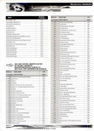
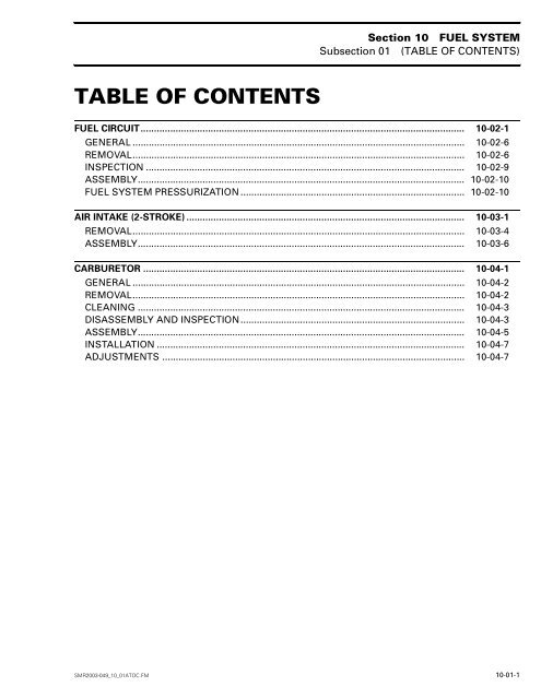
Section <strong>10</strong>Subsection 02FUEL SYSTEM(FUEL CIRCUIT)FUEL CIRCUIT 0GTI and GTI LE ModelsBody3 N•m(27 lbf•in)672 N•m(18 lbf•in)6 N•m(53 lbf•in)3121.2 N•m(11 lbf•in)1.2 N•m(11 lbf•in)22 N•m(16 lbf•ft)4 N•m4(35 lbf•in)5Dielectricgrease3 N•m(27 lbf•in)1211<strong>10</strong>4 N•m(35 lbf•in)1.2 N•m(11 lbf•in)4 N•m 4(35 lbf•in)891.2 N•m(11 lbf•in)Engine1413F06F18SSMR2003-030_<strong>10</strong>_02A.FM <strong>10</strong>-02-1
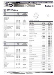
Section <strong>10</strong> FUEL SYSTEMSubsection 02 (FUEL CIRCUIT)XP DI Models6717161884522 N•m(16 lbf•ft)4 N•m(35 lbf•in)41314F08F0OS<strong>10</strong>-02-2 SMR2003-030_<strong>10</strong>_02A.FM
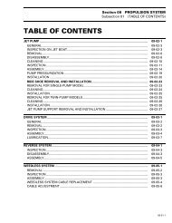
Section <strong>10</strong>Subsection 02FUEL SYSTEM(FUEL CIRCUIT)GTI LE RFI ModelsBody6 74 N•m 4(35 lbf•in)522 N•m(16 lbf•ft)118<strong>10</strong>4 N•m(35 lbf•in) 41314F02F27SSMR2003-030_<strong>10</strong>_02A.FM <strong>10</strong>-02-3
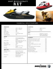
Section <strong>10</strong> FUEL SYSTEMSubsection 02 (FUEL CIRCUIT)All DI Models except XP DI67171622 N•m(16 lbf•ft)4 4 N•m(35 lbf•in)5188134 4 N•m(35 lbf•in)14F12F15S<strong>10</strong>-02-4 SMR2003-030_<strong>10</strong>_02A.FM
Section <strong>10</strong>Subsection 02FUEL SYSTEM(FUEL CIRCUIT)4-TEC Engines6744 N•m(35 lbf•in)22 N•m(16 lbf•ft)2.5 N•m(22.12 lbf•in)58134 N•m(35 lbf•in)414F18F08SSMR2003-030_<strong>10</strong>_02A.FM <strong>10</strong>-02-5
Section <strong>10</strong> FUEL SYSTEMSubsection 02 (FUEL CIRCUIT)GENERAL WARNINGDI Models: The fuel system of a fuel injectionsystem hold much more pressure than on acarbureted watercraft. Prior to disconnectinga hose or to removing a component from thefuel system, follow the recommendations describedin ENGINE MANAGEMENT (DI) underFuel System. WARNINGWhenever repairing the fuel system, alwaysverify for water infiltration in reservoir. Replaceany damaged, leaking or deterioratedfuel lines.F01B04A 11. Securing clampWhen working with fuel, pay attention to the followingwarning. WARNINGFuel is flammable and explosive under certainconditions. Always work in a well ventilatedarea. Always wipe off any fuel spillagefrom the watercraft.To secure or cut Oetiker clamps on fuel lines, usepliers (P/N 295 000 070).F01B03A1. Cutting clamp1F01B05A11. Securing clamp in limited accessWhen replacing the vent hose on all SEA-DOOmodels be sure to use “B1” hoses when replacingthe fuel supply line to the fuel rail on RFI and4-TEC models use “A1” hoses. These hoses areavailable through the Bombardier parts department.On DI models, use hoses ass’y available asparts replacement only. This will ensure continuedproper and safe operation. WARNINGUse of improper fuel lines could compromisefuel system integrity.REMOVALFuel FilterCarburetor-Equipped ModelsOpen storage compartment cover.Remove basket.XP DI ModelsOpen engine cover and remove basket.GTI, GTI LE ModelsRemove seat.<strong>10</strong>-02-6 SMR2003-030_<strong>10</strong>_02A.FM
Section <strong>10</strong>Subsection 02FUEL SYSTEM(FUEL CIRCUIT)Carburetor-Equipped ModelsTurn the fuel valve to OFF position. WARNINGThe engine must not be running and fuelvalve must be set to OFF position. Gasoline isflammable and explosive under certain conditions.Always work in a well ventilated area.Unscrew fuel filler cap to remove any fuel pressurein system.Unscrew the fuel filter bowl no. 2 counterclockwisethen pull toward the bottom.F01F01A2TYPICALStep 1 : Loosen counterclockwiseStep 2 : PullPull fuel filter no. 1 toward the bottom.1RFI ModelsThe fuel pump assembly has to be removed fromthe fuel tank to have access to the fuel filter. Referto ENGINE MANAGEMENT (RFI).Fuel filters are not replaceable on RFI models.They are lifetime reliable under the normal conditionof use.4-TEC ModelsFuel filters are not replaceable on 4-TEC models.They are lifetime reliable under the normal conditionof use.DI ModelsA replaceable inline filter is located near the fueltank. Refer to ENGINE MANAGEMENT (DI) section. WARNINGThe inline filter needs to be replaced only with4 Oetiker clamps (2 on each side).CAUTION: A pressure test needs to be completeafter replacement.Fuel Baffle Pick UpCarburetor-Equipped ModelsNOTE: The baffle pick up has an integrated fuelsender for the fuel gauge.123F01F20AF01F04A1. Pick up tube2. Fuel sensor3. Baffle pick upTYPICALSMR2003-030_<strong>10</strong>_02A.FM <strong>10</strong>-02-7
Section <strong>10</strong> FUEL SYSTEMSubsection 02 (FUEL CIRCUIT)Disconnect BLACK negative cable, then RED positivecable of battery. WARNINGAlways disconnect battery cables exactly inthe specified order, BLACK negative cable first.GTI and GTI LE ModelsOpen storage compartment cover.Remove storage basket from watercraft (if soequipped).Remove rear panel of storage compartment (if soequipped).Siphon fuel tank.Remove steering assembly. Refer to STEERINGSYSTEM for procedure.XP DI ModelsTilt seat. Refer to HULL/BODY for procedure.Remove access plug on body.Syphon fuel tank.All Models except RFI, 4-TEC and DI ModelsDisconnect fuel lines from baffle pick up and loosenlower clamp no. <strong>10</strong>.1Electric Fuel PumpRFI, 4-TEC and DI ModelsRefer to appropriate ENGINE MANAGEMENTsection.Fuel TankAll Models except 4-TEC ModelsNOTE: On all models (except RFI and LRV DI), itis necessary to remove the engine. Refer to RE-MOVAL and INSTALLATION sub section.Siphon fuel tank.Remove fuel baffle pick up or electric fuel pumpon RFI and DI models. Refer to the above section.Detach all fuel tank straps.Pull out fuel tank.4-TEC Series ModelsNOTE: It is necessary to remove the engine. Referto REMOVAL AND INSTALLATION sub section.Siphon fuel tank.Use pliers to pull out darts and remove front accesspanel.1F02F1OA2TYPICAL1. Disconnect fuel hoses2. Loosen lower clampDisconnect wiring harness of fuel sender.Remove baffle from fuel tank.Remove upper clamp no. 12 from adapter no. 11and slide adapter from baffle.Push inward on the 3 clips at the base of the bafflein order to remove the filter. Pry base off using asmall slotted screwdriver (if necessary).F18F0AA1. DartDisconnect MPEM connectors.Detach MPEM assembly and support from bilge.<strong>10</strong>-02-8 SMR2003-030_<strong>10</strong>_02A.FM
Section <strong>10</strong>Subsection 02FUEL SYSTEM(FUEL CIRCUIT)Remove TOPS switch from electrical harness orMPEM bracket.Remove air box. (Refer to AIR INTAKE SYSTEMsub section.From storage compartment disconnect fuel pumpconnections.Remove fuel pump from fuel tank. Refer to EN-GINE MANAGEMENT section.Detach reverse system support.Fuel Filter BowlCheck filter bowl for water contamination.GasketInspect gasket condition. Make sure gasket no. 3is well positioned into the filter bowl no. 2.1F18F0BA1. ScrewsRemove battery. Refer to CHARGING SYSTEMsub section.Disconnect fuel tank connections.Cut locking ties as required to release wiring harness.Detach straps with hook tool (P/N 529 035 559).Remove fuel tank from the vehicle. WARNINGCheck that fiberglass is not exposed.INSPECTIONFuel FilterAll Models except RFI, DI and 4-TEC ModelsInspect fuel filter condition. Carefully use lowpressure compressed air to clean fuel filter. Replacefilter if permanently clogged or damaged.1F01F02A1. Gasket in bowl WARNINGEnsure that there is no leakage from the fuelfilter.RFI ModelsThe filter at fuel pump inlet is not replaceable individually.The complete fuel pump unit has to bereplaced. Refer to ENGINE MANAGEMENT.DI ModelsInspect inline filter condition. Carefully use lowpressure compressed air to clean. Replace if permanentlyclogged or damaged.NOTE: The fuel filter needs to be replaced after250 hours.Fuel Filler HoseAll ModelsVerify fuel filler hose no. 5 for damage. Always ensurethat clamps no. 4 are well positioned andtightened. Torque clamps to 4 N•m (35 lbf•in).SMR2003-030_<strong>10</strong>_02A.FM <strong>10</strong>-02-9
Section <strong>10</strong> FUEL SYSTEMSubsection 02 (FUEL CIRCUIT)Pressure Relief ValveThis valve will eliminate fuel spillage when the watercraftis upside down. If pressure is built up infuel system the valve should open at 3.5 kPa (0.5PSI) for DI, 4-TEC and RFI models and at <strong>10</strong> kPa(1.5 PSI) for all other models to release the pressure. WARNINGIf pressure relief valve is stuck, the pressurein fuel system will build up and it may causefuel leakage in engine compartment.NOTE: It is a one-way valve with an arrow to indicatethe air flow.Check ValveBlack side of the one-way check valve no. 7 is thevalve outlet. It allows air to get in reservoir.Baffle Pick Up FilterAll Models except RFI, DI and 4-TECInspect filter no. 9 of baffle pick up. Clean or replaceas necessary.Fuel TankAll ModelsVisually inspect the inside and outside of the fueltank necks for crack(s). If crack(s) are existing, replacefuel tank no. 14.Check with your finger to feel the inside and outsidesurfaces of fuel tank. Flex fuel tank necks toensure there are no hidden cracks.4 2NOTE: A fuel tank is comprised of 3 components:the tank, the fuel pick up neck and the filler neck.The necks are injection molded and the tank isthen blow molded over the necks. During themolding process, a small molding seam may appearon the inner side of the necks at approximately4 mm (5/32 in) from the base of the neck. It is anormal situation to have a molding seam and itshould not be confused with a crack.ASSEMBLYAssembly is essentially the reverse of disassemblyprocedures. However pay particular attentionto the following.Reinstall fuel pump. Refer to ENGINE MANAGE-MENT section.4-TEC EnginesEnsure rubber carpet is in place.Insert tank, air box and straps.Place straps in clips (bottom) and in guides of airbox.Insert strap ends in hoops. Use tape to hold inplace.Properly secure harnesses.Reinstall fuel pump. Refer to ENGINE MANAGE-MENT section.Baffle Pick UpAll Models except RFI, DI and 4-TECSlide adapter no. 11 onto baffle pick up no. 8 untilit stops on rib. Install clamp no. 12.Install baffle pick up no. 8 into fuel tank and push ituntil it sits on fuel tank neck. Install clamp no. <strong>10</strong>and torque both clamps to 3 N•m (27 lbf•in).F07F06A3 A 51. Tank upper surface2. Inspect outside, above upper surface3. Normal molding seam4. Inspect inside, above upper surface5. Base of the neckA. Approx. 4 mm (5/32 in)1FUEL SYSTEM PRESSURIZATION WARNINGWhenever doing any type of repair on watercraftor if any components of the fuel systemare disconnected, a pressure test must bedone before starting engine. Ensure to verifyfuel line ends for damage. Always cut damagedend before reinstallation.<strong>10</strong>-02-<strong>10</strong> SMR2003-030_<strong>10</strong>_02A.FM
Section <strong>10</strong>Subsection 02FUEL SYSTEM(FUEL CIRCUIT)Pressure Test (supply and vent circuits)All ModelsProceed as follows:– Fill up fuel tank.– Disconnect air inlet hose of fuel tank from body.– Install a hose pincher (P/N 295 000 076) on fueltank vent hose.NOTE: The system must maintain a pressure of34 kPa (5 PSI) during <strong>10</strong> minutes. Never pressurizeover 34 kPa (5 PSI).Reconnect air inlet hose of fuel tank to body. WARNINGIf any leak is found, do not start the engineand wipe off any fuel leakage. Do not useelectric powered tools on watercraft unlesssystem has passed pressure test.1OUTRES2NOTE: Before removing the hose pincher, blockwith your finger the outlet fitting to feel if air iscoming out when removing hose pincher. This willindicate that pressure relief valve and the outletfitting are not blocked.Remove hose pincher from fuel tank vent hose.F01F0KATYPICAL1. Disconnect air inlet hose2. Install a hose pincher to vent hose– Connect pump gauge tester (P/N 529 021 800)to air inlet hose.NOTE: This pump is included in the ENGINE LEAKTESTER KIT (P/N 295 500 352).– Turn fuel valve to OFF position (except RFI, DIand 4-TEC).– Pressurize fuel system to 34 kPa (5 PSI).– If no leaks are found, turn fuel valve to ON positionand pressurize once more.– If pressure is not maintained locate leak andrepair/replace component leaking. To ease leaksearch spray a solution of soapy water on components,bubbles will indicate leak location.High Pressure Test (fuel pump circuit)RFI, DI and 4-TEC ModelsRefer to the appropriate ENGINE MANAGEMENTsection. WARNINGPrior to installing the safety lanyard, refer tothe appropriate ENGINE MANAGEMENT sectionfor safety precautions to take.SMR2003-030_<strong>10</strong>_02A.FM <strong>10</strong>-02-11
Section <strong>10</strong> FUEL SYSTEMSubsection 03 (AIR INTAKE (2-STROKE))AIR INTAKE (2-STROKE) 0717 Engines13<strong>10</strong> N•m(89 lbf•in)294<strong>10</strong> N•m(89 lbf•in)8567Loctite 518<strong>10</strong> N•m(89 lbf•in)<strong>10</strong>Loctite243Loctite 243Loctite 51815F02F2CSLoctite 243SMR2003-031_<strong>10</strong>_03A.FM <strong>10</strong>-03-1
Section <strong>10</strong> FUEL SYSTEMSubsection 03 (AIR INTAKE (2-STROKE))787 RFI Engines1<strong>10</strong> N•m(89 lbf•in)2Loctite243934<strong>10</strong>Loctite243<strong>10</strong> N•m(89 lbf•in)5<strong>10</strong> N•m(89 lbf•in)867F15F01T<strong>10</strong>-03-2 SMR2003-031_<strong>10</strong>_03A.FM
Section <strong>10</strong> FUEL SYSTEMSubsection 03 (AIR INTAKE (2-STROKE))947 DI EnginesLoctite 24321211XP DI only14Loctite 2434SuperLubeLoctite243Loctite 243133F18F0NSSMR2003-031_<strong>10</strong>_03A.FM <strong>10</strong>-03-3
Section <strong>10</strong> FUEL SYSTEMSubsection 03 (AIR INTAKE (2-STROKE))REMOVAL717 and 787 RFI EnginesAir Intake Silencer CoverUnlock the 6 retaining slides holding air intake silencercover no. 1 and remove cover.1 2Flame Arrester BaseRemove flame arrester no. 5.Remove screws no. 8 retaining support no. 6 offlame arrester base to the cylinder head cover (717engines) or to the exhaust manifold (787 engines).1F01F2OATYPICAL1. Air intake silencer cover2. UnlockAir Intake Silencer BaseRemove screws no. 2 of retaining plate no. 3.Pull out retaining plate no. 3 and air intake silencerbase no. 4.1F00F03ATYPICAL1. Remove supportRemove screws no. <strong>10</strong> from flame arrester basethen withdraw base.NOTE: On GTI and GTI LE models, withdrawboth arrester supports no. 15.947 DI EnginesAir Intake SilencerPull hair pin out to allow removal of clip no. 2.32F00F02A211. Retaining plate2. Remove screwsF00F0FA1. Air intake silencer2. Clip3. Hair pin<strong>10</strong>-03-4 SMR2003-031_<strong>10</strong>_03A.FM
Section <strong>10</strong> FUEL SYSTEMSubsection 03 (AIR INTAKE (2-STROKE))Unlock the clip no. 2 on top of air intake silencer.Remove bolts retaining both air ducts to engine (bothsides).XP DI ModelsDetach 2 straps from the oil reservoir using springremover tool (P/N 529 035 559).529 035 559F08F08A 111. Remove boltsPull air ducts out.1F12F16AUnclip oil filter. Pull oil reservoir out.Remove foam under the fuel tank.Remove air ducts and protector pads of air silencer.Pull the air silencer forward to remove it from thelower bracket no. 4 and remove it in a rotating movement.F08F09A1. Air ductNOTE: Do not disconnect oil lines.Push the air intake silencer out of the carburetoradapter no. 3 and throttle body.RX DI ModelsPull the air intake silencer rearward to remove itfrom the lower bracket no. 4 and remove it in arotating movement.F08F0AAXP DI MODELSThe air intake silencer is a molded piece and it cannot be opened. It has an integrated flame arrester.SMR2003-031_<strong>10</strong>_03A.FM <strong>10</strong>-03-5
Section <strong>10</strong> FUEL SYSTEMSubsection 03 (AIR INTAKE (2-STROKE))ASSEMBLYAssembly is essentially the reverse of removal procedures.However pay particular attention to the following.CAUTION: Do not modify air intake system,otherwise calibration will be affected.717 EnginesFlame Arrester BaseApply Loctite 518 on mating surfaces of flame arresterbase no. 7.Apply Loctite 243 (blue) on screws no. <strong>10</strong> andtorque to <strong>10</strong> N•m (88 lbf•in).Flame ArresterInspect condition of flame arrester no. 5. Replaceor clean as necessary. WARNINGDo not operate watercraft without flame arrester. WARNINGWhile doing so, ensure that the clip snapsfirmly, securing the air intake silencer in atight fit; if not, bend the clip using pliers untilyou feel that the clip is tight enough.Properly reinstall hair pin to secure clip no. 2.Ensure the elbow adaptor is well inserted and thatit has not pushed the gasket inside the air intakesilencer.NOTE: Make sure the air intake silencer is retainedby the lower bracket no. 4.Place protector pads on duct supports. Use slot inrubber to insert pad on bracket eyelet. Side tongueof protector pad should be toward outside of vehicleand bent downward toward the exhaust flange.Put air ducts in intake adapters and secure themon duct supports with hexagonal screws no. 13,wide washers, narrow washers and elastic stopnuts. A slight lift will be required to make the boltsline up with brackets.12 3 7 8GasketInspect condition of gasket no. 9. Make sure to properlyinstall gasket.947 DI EnginesAir Intake SilencerEnsure that support plate edges no. 14 are properlycrimped to air intake silencer. Use pliers asnecessary.Make sure that gaskets no. 11 are installed intothrottle bodies.Check O-rings no. 12 on throttle bodies and changethem if necessary.NOTE: Apply Super Lube grease (P/N 293 550 014)to mating surface of air intake silencer no. 1.Install air intake silencer on throttle bodies andlatch in place.Clip air intake silencer back in place.F06F0VATYPICAL — 947 DI ENGINES1. Hexagonal screw M62. Wide flat washer3. Insulator4. Air duct5. Protector pad6. Duct support eyelet7. Narrow flat washer8. Hexagonal stop nut M64 6 5<strong>10</strong>-03-6 SMR2003-031_<strong>10</strong>_03A.FM
Section <strong>10</strong>Subsection 04FUEL SYSTEM(CARBURETOR)CARBURETOR 0For fuel system on RFI, DI and 4-TEC models, refer to appropriate ENGINE MANAGEMENT section.Mikuni BN-40i122020 N•m(15 lbf•ft)20SyntheticgreaseLoctite24321 13146Syntheticgrease11938Loctite 2437211315Anti-seizelubricant195418 1716F17F01SSMR2003-032_<strong>10</strong>_04A.FM <strong>10</strong>-04-1
Section <strong>10</strong> FUEL SYSTEMSubsection 04 (CARBURETOR)GENERALThe following illustration shows which part of thecarburetor begins to function at different throttleplate openings.14522F01F13A63VIEW FROM AIR INTAKE OPENING1. Throttle plate openings2. Throttle plate closed3. Throttle plate wide opened4. Low-speed screw5. Pilot jet6. Main jet and high-speed screwThe carburetor is equipped with a fuel acceleratorpump.The fuel accelerator pump is linked to the throttlevalve via a linkage.A metering jet in the fuel inlet hose controls fuelflow to the pump.A check valve on the fuel outlet hose helps toprime the system.REMOVALTo remove carburetor from engine, proceed as follows:Remove air vent tube support (GTI and GTI LEmodels).Remove air intake silencer. Refer to AIR INTAKE.Turn fuel valve to OFF position.Disconnect pulse line.1F06F0LATYPICAL1. Pulse line2. Loosen gear clampDisconnect fuel supply line from fuel pump.Disconnect fuel return line.Disconnect oil injection pump cable, throttle cableand choke cable.Remove screws no. 20 and lock washers no. 21retaining carburetor.F07F03A1TYPICAL1. Remove screwsRemove carburetor.1 11<strong>10</strong>-04-2 SMR2003-032_<strong>10</strong>_04A.FM
Section <strong>10</strong>Subsection 04FUEL SYSTEM(CARBURETOR)CLEANINGThe carburetor exterior surfaces should be cleanedwith a general solvent and dried with compressedair before disassembly.CAUTION: Be careful at carburetor cleaning notto remove paint. Paint removal will cause carburetorto rust very rapidly. Repaint if necessary.Carburetor body and jets should be cleaned witha carburetor cleaner. Follow manufacturer’s instructions. WARNINGSolvent with a low flash point such as gasoline,naphtha, benzol, etc., should not be usedas they are flammable and explosive.CAUTION: Heavy duty carburetor cleaner maybe harmful to the rubber parts, O-rings, etc.Therefore, it is recommended to remove theseparts prior to cleaning.Inspect O-rings, diaphragms and gaskets.DISASSEMBLY AND INSPECTIONInspect parts for corrosion damage (shaft, throttleplate, spring, screw, check valve housing, etc.).Needle ValveInspect needle valve tip for a grooved condition. Ifworn, needle and seat must be replaced as amatched set.Low Speed ScrewCheck tip of low speed screw no. 2 for a groovedcondition. Replace if necessary.DiaphragmPump Diaphragm Leak TestUsing a suitable pump gauge tester, perform thefollowing test proceeding as follows:– Install pump gauge tester (P/N 295 000 114) onpulse nipple.– Pump tester until it reaches 28 kPa (4 PSI).F01F0XATYPICAL1. Pump gauge tester2. Install on pulse nippleDiaphragm must stand pressure for <strong>10</strong> seconds.If pressure drops, replace diaphragm no. 3.Fuel Pump ValveCheck fuel pump valve operation as follows:Connect a clean plastic tubing to the inlet nipple of thefuel pump body no. 4 and alternately apply pressureand vacuum with the mouth. The inlet valve shouldrelease with pressure and hold under vacuum. WARNINGSome fuel may be present in fuel pump. Becareful not to swallow fuel when under vacuum.F01F0WATYPICAL1. Fuel outlet nipple2. Pulse nipple3. Inlet nipple2Repeat the same procedure at the outlet nipple ofthe fuel pump body no. 4. This time the outletvalve should hold with pressure and release undervacuum.Inspect valves. The pumping area should be freeof holes, tears or imperfections. Replace as needed.1312SMR2003-032_<strong>10</strong>_04A.FM <strong>10</strong>-04-3
Section <strong>10</strong> FUEL SYSTEMSubsection 04 (CARBURETOR)Internal Fuel FilterTo verify condition of filter no. 5, proceed as follows:Remove pump cover no. 16, gasket no. 17, diaphragmno. 18 and then pump body no. 4 and diaphragmno. 19.Remove filter no. 5 from carburetor body thenclean filter and blow carefully with compressed air(low pressure).Replace filter if damaged.– Obstruct outlet nipple with a finger and holdwhile pumping.– Pump tester until it reaches 28 kPa (4 PSI).1 2 3F01F0YATYPICAL1. FilterFuel Accelerator PumpDisconnect inlet and outlet hoses from acceleratorpump nipples.1F06F07A1. Pump gauge tester2. Hose installed to inlet nipple3. Outlet nipple obstructedDiaphragm must stand pressure for <strong>10</strong> seconds.If pressure drops, replace accelerator pump diaphragm.Verify accelerator pump check valves operation asfollows:Connect a clean plastic tubing to the valve inletnipple and alternately apply pressure and vacuum.The check valve should release with pressure andhold under vacuum. WARNINGSome fuel may be present in fuel pump.F06F06A 1 2TYPICAL1. Fuel inlet hose2. Fuel outlet hoseUsing a suitable pump gauge tester, perform thefollowing test proceeding as follows:– Install pump gauge tester (P/N 295 000 083) oninlet nipple of accelerator pump no. 22.F06F08A 1TYPICAL1. Apply pressure and vacuum at inlet nipple<strong>10</strong>-04-4 SMR2003-032_<strong>10</strong>_04A.FM
Section <strong>10</strong>Subsection 04FUEL SYSTEM(CARBURETOR)To check the injector, install pump gauge tester tothe injector hose.NOTE: Injectors are also equipped with checkvalves.1Needle Valve LeverRounded end of needle valve lever no. 8 must beflush with surrounding metering chamber floorand not with body assembly. Place the end of aruler over lever to check adjustment.312F04F0JB2TYPICAL1. Install pump gauge tester to injector hose2. InjectorPump tester. Injector check valve should open at19.4 kPa ± 4.7 (2.8 ± .6 PSI).NOTE: If the obtained pressure is too low, thecheck valve is leaking. If it is too high, less fuel willbe delivered which may lead to engine hesitationunder acceleration.ASSEMBLYWhen assembling pump, ensure to properly positioncomponents together. Refer to previous illustrationsif necessary.Choke Plate and Throttle PlateWhen installing plate no. 6 onto shaft no. 7, closeplate so that it centers into carburetor bore. Firmlytighten screws.CAUTION: Always apply Loctite 243 (blue) onscrew threads prior to installing screws.F01F0ZA1. Metering chamber floor2. Lever end3. FlushTo adjust, bend lever very slightly to change its height.CAUTION: When adjusting lever, do not pry itso that it applies pressure on needle. This coulddamage valve seat/needle.1F01F0HAHIGH LEVERStep 1 : Depress hereStep 2 : Push tab down2SMR2003-032_<strong>10</strong>_04A.FM <strong>10</strong>-04-5
Section <strong>10</strong>Subsection 04FUEL SYSTEM(CARBURETOR)Check Valve AssemblyThe check valve is needed if a back pressure occursinto carburetor. It will prevent fuel from flowingback into carburetor lower portion.Inspect check valve no. 11. It should be free ofholes, tears or imperfections. Replace as needed.F01F12A1. Check valveNOTE: Prior to check valve assembly installation,remember to set gasket.Diaphragm and CoverInstall diaphragm no. 3 with its integrated O-ringinto carburetor groove. Make sure that the tab ofcover no. 12 is inserted into carburetor notch.O-RingWhen installing O-rings no. 13 of low speed andhigh speed screws, apply some BOMBARDIERLUBE (P/N 293 600 016) to prevent sticking.Fuel Accelerator PumpLubricate pump plunger, roller and cam with syntheticgrease (P/N 293 550 0<strong>10</strong>) and roller shaftwith BOMBARDIER LUBE (P/N 293 600 016).1INSTALLATIONCarburetorAt installation, pay attention to the following:Install carburetor with gasket to intake manifold(rotary valve cover).Apply synthetic grease on screws no. 20. Then,install screws no. 20 with lock washers no. 21and torque to 20 N•m (15 lbf•ft).Fuel Lines and Hose ClampsIf fuel line ends are damaged, cut damaged endbefore reinstallation.Properly install clamps. WARNINGMake sure there is no leak in fuel system.For fuel system pressurization, refer to FUEL CIR-CUIT.ADJUSTMENTSCarburetor AdjustmentCalifornia ModelsThere is no mixture adjustment to be performedby the dealer.IMPORTANT: Trying to bypass the anti-tamperscrews could damage the carburetor. It could alsochange the engine emission level and lead the enginenot to meet the California emission control regulations.Throttle Cable AdjustmentNOTE: Do not activate throttle lever unnecessarily.Carburetor is equipped with fuel acceleratorpump. This pump is injecting fuel into carburetorseach time throttle lever is depressed.Lubricate cable with BOMBARDIER LUBE lubricant.Throttle lever must reach handlebar grip withoutcausing strain to cable or carburetor cable bracket.F06F06B 2 1TYPICAL1. Apply synthetic grease to plunger2. Apply BOMBARDIER LUBE on roller shaftSMR2003-032_<strong>10</strong>_04A.FM <strong>10</strong>-04-7
Section <strong>10</strong> FUEL SYSTEMSubsection 04 (CARBURETOR)F01K08A1CAUTION: Improper oil injection pump synchronizationwith carburetor can cause serious enginedamage.All Models except California ModelsLow Speed Screw Adjustment1. Must touch handlebar gripEnsure carburetor throttle plate(s) is (are) fully openat full throttle position. At this position, throttle leverstopper is almost in contact (0.5 mm (1/64 in))with carburetor body.NOTE: Apply a light pressure on the throttle plate(s),a slight play should be obtained.CAUTION: Improper cable adjustment will causestrain on cable and/or damage cable bracket orthrottle lever at handlebar.To adjust, loosen jam nut then turn adjustment nutas necessary.1F06F0GA1. Low speed screwCAUTION: Do not attempt to set engine idle speedwith low-speed screw.Tighten low speed screw until a slight resistanceis felt. Then, back it off to the specification as perfollowing chart.ENGINE TYPELOW SPEED SCREW717 1.0 ± 0.25 turnsF01G0YC 3 1 21. Adjustment nut2. Jam nut3. Throttle lever stopperTighten jam nut and recheck adjustment. WARNINGMake sure idle speed screw contacts stopperwhen throttle lever is fully released at handlebar.After throttle cable adjustment, always proceedwith the oil injection pump cable adjustment. Referto OIL INJECTION PUMP.NOTE: Turning screw clockwise leans mixture andturning screw counterclockwise enriches mixture.Start and warm up engine.CAUTION: If watercraft is out of water, enginemust be cooled using the flush kit.Check that engine idles and runs smoothly. Makesure engine reacts quickly to throttle lever depression.If necessary, readjust low speed screw(± 1/4 turn).High Speed ScrewThe high speed screw no. 14 is sealed with a plasticcap that allows an adjustment of 1/4 turn.NOTE: Turning screw 1/4 turn counterclockwise enrichesmixture and turning screw clockwise leansmixture.CAUTION: Do not attempt to adjust high speedscrew by removing plastic cap.<strong>10</strong>-04-8 SMR2003-032_<strong>10</strong>_04A.FM
Section <strong>10</strong>Subsection 04FUEL SYSTEM(CARBURETOR)Fuel Accelerator PumpAll EnginesEnsure throttle cable and idle speed are properlyadjusted.With the engine not running, loosen adjustmentscrew lock nut. Use a feeler gauge between levertab and pump plunger. Turn adjustment screw toachieve approximately 0.05 - 0.15 mm (.002 - .005 in)gap. Tighten adjustment screw lock nut.1F06F0IA 11. High speed screwIdle Speed ScrewTurning screw no. 15 clockwise increases engineidle speed and turning screw counterclockwise decreasesengine idle speed.1F02F1QA2TYPICAL1. Adjustment screw2. Small gapNOTE: Turning the adjustment screw clockwise willincrease the gap.Choke CableEnsure choke lever has a free-play of 0.5 to 2.0 mm(1/64 to 5/64 in).F01G0YD1. Idle speed screwConnect an induction-type tachometer (P/N 529014 500) on spark plug cable of mag<strong>net</strong>o side tomeasure engine speed.NOTE: To adjust idle speed, ensure flame arresterand air intake silencer are installed.Start engine and bring to normal operating temperature.CAUTION: If watercraft is out of water, enginemust be cooled using the flush kit.Turn screw so that engine idles at 1500 RPM inwater or 3000 RPM out of water.F07F02ATYPICAL1. Choke leverA. Free play of 0.5 to 2.0 mm (1/64 to 5/64 in)To adjust, loosen jam nut on carburetor bracket,then turn adjustment nut as necessary.Tighten jam nut and recheck adjustment.A1SMR2003-032_<strong>10</strong>_04A.FM <strong>10</strong>-04-9