09 - Sea-Doo.net
09 - Sea-Doo.net
09 - Sea-Doo.net

You also want an ePaper? Increase the reach of your titles
YUMPU automatically turns print PDFs into web optimized ePapers that Google loves.
Section <strong>09</strong> PROPULSION SYSTEMSubsection 01 (TABLE OF CONTENTS)TABLE OF CONTENTS 0JET PUMP .............................................................................................................................. <strong>09</strong>-02-1GENERAL ........................................................................................................................... <strong>09</strong>-02-3INSPECTION ON JET BOAT.............................................................................................. <strong>09</strong>-02-3REMOVAL........................................................................................................................... <strong>09</strong>-02-6DISASSEMBLY................................................................................................................... <strong>09</strong>-02-8CLEANING ......................................................................................................................... <strong>09</strong>-02-10INSPECTION ...................................................................................................................... <strong>09</strong>-02-11ASSEMBLY......................................................................................................................... <strong>09</strong>-02-14PUMP PRESSURIZATION ................................................................................................. <strong>09</strong>-02-19INSTALLATION .................................................................................................................. <strong>09</strong>-02-20RIDE SHOE REMOVAL AND INSTALLATION.................................................................. <strong>09</strong>-02-23REMOVAL FOR SINGLE-PUMP MODEL .......................................................................... <strong>09</strong>-02-23CLEANING ......................................................................................................................... <strong>09</strong>-02-24INSTALLATION.................................................................................................................. <strong>09</strong>-02-25REMOVAL FOR TWIN-PUMP MODELS............................................................................ <strong>09</strong>-02-25CLEANING ......................................................................................................................... <strong>09</strong>-02-26INSTALLATION.................................................................................................................. <strong>09</strong>-02-26JET PUMP SUPPORT REMOVAL AND INSTALLATION................................................. <strong>09</strong>-02-27DRIVE SYSTEM ..................................................................................................................... <strong>09</strong>-03-1GENERAL ........................................................................................................................... <strong>09</strong>-03-2REMOVAL........................................................................................................................... <strong>09</strong>-03-2INSPECTION ...................................................................................................................... <strong>09</strong>-03-3ASSEMBLY......................................................................................................................... <strong>09</strong>-03-4LUBRICATION.................................................................................................................... <strong>09</strong>-03-7REVERSE SYSTEM................................................................................................................ <strong>09</strong>-04-1INSPECTION ...................................................................................................................... <strong>09</strong>-04-3DISASSEMBLY................................................................................................................... <strong>09</strong>-04-3ASSEMBLY......................................................................................................................... <strong>09</strong>-04-5WEEDLESS SYSTEM ............................................................................................................ <strong>09</strong>-05-1REMOVAL .......................................................................................................................... <strong>09</strong>-05-2INSPECTION ...................................................................................................................... <strong>09</strong>-05-3ASSEMBLY ........................................................................................................................ <strong>09</strong>-05-3WEEDLESS SYSTEM CABLE REPLACEMENT ................................................................ <strong>09</strong>-05-4CABLE ADJUSTMENT ...................................................................................................... <strong>09</strong>-05-6<strong>09</strong>-01-1
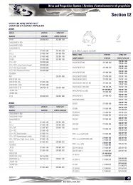
Section <strong>09</strong> PROPULSION SYSTEMSubsection 02 (JET PUMP)JET PUMP 0Single-Pump ModelRight StuffGasket12Adseal451111Loctite242Right StuffGasket1010 N•m(89 lbf•in)1413171920Loctite271Loctite51818Adseal4511LoctitePipe<strong>Sea</strong>lant24Adseal4511Loctite2716Loctite242265 28 N•m(21 lbf•ft)Loctite51872930F04J46STYPICAL202122Loctite2712570 N•m(52 lbf•ft)LoctitePipe <strong>Sea</strong>lant4 N•m (35 lbf•in)Loctite518Loctite 823 27 242 21 N•m28(15 lbf•ft)15Jet PumpSynthetic Oil164 N•m(35 lbf•ft)3Loctite2424320 N•m1(15 lbf•ft)<strong>09</strong>-02-1
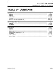
Section <strong>09</strong> PROPULSION SYSTEMSubsection 02 (JET PUMP)Twin-Pump ModelsAdseal4511Adseal 4511Right Stuff GasketLoctite 242Port sideAdseal451111Right StuffGasketLoctite 24212Starboard910 N•m(89 lbf•in)26Adseal4511HullRight StuffGasket141317 AdsealLoctite 451151819 20Loctite2711810 N•m(89 lbf•in)31 N•m(23 lbf•ft)Loctite2716528 N•m(21 lbf•ft)Loctite Primer NandLoctite 51820 N•m7 1(15 lbf•ft)3264F<strong>09</strong>J07TTYPICALLoctite Primer NandLoctite 27120212270 N•m(52 lbf•ft)Loctite Primer Nand Pipe <strong>Sea</strong>lant(P/N 293 800 013)252321 N•m(15 lbf•ft)Loctite518Jet PumpSynthetic Oil8Loctite2424 N•m(35 lbf•in)1513 N•m(115 lbf•in)<strong>09</strong>-02-2
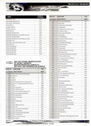
Section <strong>09</strong> PROPULSION SYSTEMSubsection 02 (JET PUMP)GENERALSome pump components can be changed to improveboat performance in high altitude regionsbetween 1500 - 3000 m (5000 - 10 000 ft). Referto the service department for the latest specifications.- CAUTIONSuch modifications should only be performedby experienced mechanics since they cangreatly affect vehicle performance.The jet pump housing and venturi are made of plastic.Impeller IdentificationTo identify the impellers no. 17 refer to the followingillustration and chart.1; WARNINGAlways remove safety lanyard from DESSpost to prevent unattended engine startingprior to working on the jet pump/ride shoe.INSPECTION ON JET BOATTo work on boat, securely install it on a stand.Thus, if access is needed to water inlet area, it willbe easy to slide underneath boat.A lift kit can be used to install boat on a stand. Seetable below. Refer to the kit instruction sheets forproper use.BOAT MODELKIT P/N14 feet 295 000 16018 feet 295 100 045Impeller ConditionCondition of impeller, boot and ring can be quicklychecked from underneath of the jet boat. Lowergrill and look through water inlet opening.1F02J0VA1. Stamped part numberBOATMODELIMPELLERP/NMATERIALPITCHSportster 271 000 416Challenger 271 000 821StainlesssteelStainlesssteelProgressivepitchProgressivepitchF01J0DA1. Boot with ringSportster1800204 160 065StainlesssteelProgressivepitchChallenger1800204 160 048StainlesssteelProgressivepitch<strong>09</strong>-02-3
Section <strong>09</strong> PROPULSION SYSTEMSubsection 02 (JET PUMP)Oil VerificationRemove plug from cover.F02J0TB 1F01J5IA 11. Remove plugCheck oil level, it should be at bottom of holethreads.If oil level is low, check impeller shaft housing forleaks. A pressure test must be performed. Referto Pump Pressurization in this section.To check oil condition, insert a wire through openingthen withdraw. A whitish oil indicates water contamination.This may involve defective impeller shaft sealand/or O-ring of housing cover. Jet pump unitshould be overhauled to replace seal.If everything is correct, apply Loctite Primer N(P/N 293 800 041) then Loctite Pipe <strong>Sea</strong>lant (P/N293 800 018) on plug and reinstall it on cover.Properly reinstall removed parts.Oil ReplacementRemove parts as described in Oil Inspection.Remove 3 screws retaining cover.1. ScrewsUsing a fiber hammer, gently tap cover no. 15 torelease it from housing no. 6. Be careful as coveris spring loaded.Thoroughly clean reservoir and inside of coverwith a solvent. Check O-ring no. 23 condition. Replaceas necessary.Apply a thin layer of Loctite 518 (P/N 293 800 038)on mating surface of cover and reinstall it with itsO-ring. Torque screws to 4 N•m (35 lbf•in).Remove plug from cover.Pour oil through hole until oil reaches the bottomof hole threads. Use <strong>Sea</strong>-<strong>Doo</strong> jet pump syntheticoil (P/N 293 600 011) only. Oil will pe<strong>net</strong>rate slowlyin center area of housing, wait a few minutesand readjust oil level.- CAUTIONThis is a synthetic oil. Do not mix with mineralbased oil. Do not mix oil brands.Apply Loctite Primer N (P/N 293 800 041) thenLoctite Pipe <strong>Sea</strong>lant (P/N 293 800 018) on plugand reinstall it on cover.Properly reinstall removed parts.<strong>09</strong>-02-5
Section <strong>09</strong> PROPULSION SYSTEMSubsection 02 (JET PUMP)Impeller HousingNOTE: In the following procedure, impeller housingno. 6 is removed as an assembly with nozzleand venturi/reverse gate support.Single-Pump ModelFrom inside bilge, disconnect coolant inlet hosefrom impeller housing no. 6.If pump is hard to remove, use a curved pry bar,apply electrical tape around the curved end in orderto protect hull and pry to remove pump.F04P0LAF04E0NAAll ModelsDisconnect adjuster of steering cable from nozzleno. 4 (refer to Oil Level Inspection above formore details pertaining to twin-pump models).Remove ball joint fasteners to release reverse cablefrom reverse gate.Remove nuts retaining impeller housing no. 5 tohull.Pry pump evenly ensuring not to damage thethreaded studs.- CAUTIONSome boats may be equipped with shims.Ensure to note location of these shims at removalfor reinstallation purposes.F04L52AF04J2PA 1TYPICAL — VIEW OF A TWIN-PUMP MODEL1. Remove nutsRemove jet pump assembly with a wiggle movement.NOTE: If jet pump cannot be removed, the driveshaft may be seized in the impeller splines. Referto PROPULSION SYSTEM <strong>09</strong>-04 to remove driveshaft at the same time. If ride shoe needs to beremoved, refer to Ride Shoe Removal and Installationat the end of this section.<strong>09</strong>-02-7
Section <strong>09</strong> PROPULSION SYSTEMSubsection 02 (JET PUMP)Single-Pump ModelRemove spacer ring from ride shoe only if leakageis suspected (ventilation problem).DISASSEMBLYAll ModelsNOTE: Whenever removing a part, visually checkfor damage such as: corrosion, crack, split, break,porosity, cavitation, deformation, distortion, heatingdiscoloration, wear pattern, missing plating,missing or broken needle on needle bearing, waterdamage diagnosed by black-colored spots,etc. Renew any damaged part. As a quick check,manually feel clearance and end play, where applicable,to detect excessive wear.FittingFitting no. 24 can be removed with deep socketor vise grip (not required on twin-pump models).Do not touch hose mounting area.Fitting can be removed from pump housing no. 6with following suggested tool:– Use a 14 mm (9/16 in) deep socket.– Drill deep socket with a 14 mm (9/16 in) drill bit,starting at hexagon head end as shown in followingillustration.– Drill a 2.40 mm (3/32 in) hole in center of deepsocket as shown in following illustration.– Install 2.40 mm (3/32 in) roll pin in the centerhole.1ACoverWith pump assembly in horizontal position, remove3 retaining screws no. 16.Place a container under cover no. 15 to catch oil.Using a fiber hammer, gently tap cover to releaseit from impeller housing. Be careful as cover isspring loaded.ImpellerInsert impeller shaft holder (P/N 295 000 082) onimpeller shaft flat end.Using 2 screws previously removed from venturino. 7, secure shaft holder to housing.F00J07A 11. Shaft holderTo ease removal heat impeller no. 17 center witha propane torch to approximately 150°C (300°F) tobreak the Loctite bond.Impeller is loosened using impeller remover tool(P/N 295 000 001).Install shaft holder in a vice.BF01J2RA21. Deep socket 14 mm (9/16 in)2. Roll pin 2.40 mm (3/32 in)A. 42.50 mm (1-43/64 in)B. 36.80 mm (1-29/64 in)<strong>09</strong>-02-8
Section <strong>09</strong> PROPULSION SYSTEMSubsection 02 (JET PUMP)1Wear RingPlace impeller housing no. 6 in a vise with softjaws. It is best to clamp housing using a lower ear.Cut wear ring no. 18 at 2 adjacent places.NOTE: Wear ring can be cut using a jigsaw, a smallbuffer or a low clearance hacksaw such as SnaponHS3 or equivalent.- CAUTIONWhen cutting ring, be careful not to damageimpeller housing.F00J0HA1. Impeller shaft holder secured in a viceImpeller is loosened using impeller remover tool(P/N 295 000 001).1F01J0VATYPICALF00J08A1. Impeller remover toolRotate impeller remover tool counterclockwise andunscrew completely impeller.- CAUTIONNever use any impact wrench to loosen impeller.To remove impeller, apply a rotating movementand pull at same time. Slide impeller out of housingand remove tool from impeller.F01J0WA1. Snap-on HS3After cutting ring, insert a screwdriver blade betweenimpeller housing and ring outside diameter.Push ring so that it can collapse internally.Pull ring out.1<strong>09</strong>-02-9
Section <strong>09</strong> PROPULSION SYSTEMSubsection 02 (JET PUMP)Impeller ShaftRemove shaft holder tool.Remove impeller shaft no. 25 with thrust washerand thrust bearing.<strong>Sea</strong>l and Needle BearingRemove seal no. 19 and bearings no. 20 at thesame time using bearing/seal remover tool (P/N295 000 144).CLEANING<strong>Sea</strong>lant can be removed with a wire brush (disc)mounted on a drill or a scraper (not required ontwin-pump models).Properly clean all threads.Remove all O-rings and clean parts in a solvent.Carefully check water passages (Cooling system)and oil passages. Blow low pressure compressedair through them and make sure they are clear.1F01J11AInsert bearing remover then press tool using a arborpress until seal and bearings are out. However,care should be taken not to damage bearingjournals.F01J13B211. Water passages2. Oil passagesBrush and clean impeller shaft threads, impellerand drive shaft splines with Loctite Parts cleaner(P/N 413 711 8<strong>09</strong>) or equivalent. Free threads andsplines from any residue.- CAUTIONBe careful not to damage impeller shaft diameter.F00J0MA1. Bearing/seal remover toolNOTE: It is always recommended to renew bothbearings, even if only one bearing needs to be replaced.Single-Pump ModelIf the spacer ring has been removed from rideshoe no. 26, clean spacer ring and ride shoe areawith acetone.<strong>09</strong>-02-10
Section <strong>09</strong> PROPULSION SYSTEMSubsection 02 (JET PUMP)INSPECTIONAll ModelsImpellerVisually inspect impeller no. 17 splines. Check forwear or deformation. Renew parts if damaged.NOTE: Check also PTO flywheel and drive shaftcondition. Refer to PROPULSION SYSTEM <strong>09</strong>-04.Examine impeller in wear ring for distortion.Check if blade tips are blunted round, chipped orbroken. Such impeller is unbalanced and will vibrateand damage wear ring, impeller shaft, shaftseal or bearings. Renew if damaged.F02J0VB1. Replace if blunted round or damaged1Check impeller for cavitation damage, deep scratchesor any other damage.Wear RingCheck wear ring no. 18 for deep scratches, irregularsurface or any apparent damage.If impeller/wear ring clearance is too large and impellerno. 17 is in good shape, renew wear ring.Needle Bearing and Impeller ShaftWearInspect needle bearings no. 20 and their contactsurface. Check for scoring, pitting, chipping orother evidence of wear.With a finger nail, feel contact surface of seal. Ifany irregular surface is found, renew impeller shaftno. 25.Install bearings then install impeller shaft and rotateit. Make sure it turns smoothly.Radial PlayRadial play is critical for jet pump unit life span.Radial play of impeller shaft is checked with shaftin housing, without impeller.Retain housing in a brass jaw vise making sure notto damage housing lug.Set a dial gauge and position its tip onto shaft end,close to end of threads.Move shaft end up and down. Difference betweenhighest and lowest dial gauge reading is radialplay.Maximum permissible radial play is 0.05 mm(.002 in).11F02J0UA1. Check for cavitation, deep scratches or other damageF01J18A2MEASURING IMPELLER SHAFT RADIAL PLAY1. Dial gauge2. Measure close to threads at shaft end<strong>09</strong>-02-11
Section <strong>09</strong> PROPULSION SYSTEMSubsection 02 (JET PUMP)To check both bearings, proceed the same waywith other shaft end. Position gauge tip on diameter,close to flats on shaft.1NOTE: If shaft is to be replaced, it is recommendedto replace both bearings at the same time. Inaddition, it is suggested to replace thrust bearingand thrust washer.Thrust Washer and Thrust BearingVisually inspect thrust washer no. 21, thrust bearingno. 22 and their contact surface. Check forscoring, pitting, flaking, discoloration or other evidenceof wear.1 23F01J19A2MEASURING IMPELLER SHAFT RADIAL PLAY1. Dial gauge2. Measure close to flats at shaft endExcessive play can come either from worn bearingsor impeller shaft or damaged impeller housingbearing surfaces.Measuring shaft diameter will determine defectivepart.Using a micrometer, measure diameter on bearingcontact surfaces. Minimum shaft diameter shouldbe 22.24 mm (.876 in).F01J1AA1. Inspect for wear at the bearing pilot2. Radial bearing raceway21F01J52ATYPICAL1. Worn roller (trunnion worn on end of roller)2. Good roller (cylindrical shape)3. Look for scoring on retainerNOTE: When replacing either washer or bearing,it is recommended to renew both.Cover and Impeller ShaftEnd PlayEnd play of impeller shaft no. 25 is checked withshaft in housing, without impeller no. 17 and withhousing cover no. 15 installed.Retain housing in a brass jaw vise making sure notto damage housing lug. Set a dial gauge and positionits tip on the end of shaft. Move shaft end bypulling and pushing. Difference between highestand lowest dial gauge reading is end play. Maximumpermissible end play (new) is 0.12 - 0.54 mm(.005 - .021 in).<strong>09</strong>-02-12
Section <strong>09</strong> PROPULSION SYSTEMSubsection 02 (JET PUMP)1F00J0QAAF01J2SA1. Tip on shaft endExcessive play comes from worn protrusion insidehousing cover and wear of impeller shaft nose.Using pliers, remove anti-knock pusher no. 27and spring no. 28 from cover no. 15.A. Wear limit 8.0 mm (.315 in)Pusher should be replaced if it is not within specification.Be sure to check end play after installing a newpusher.Inspect impeller shaft nose for wear.F00J<strong>09</strong>A 1TYPICAL1. PusherInspect pusher for any damage or deterioration.Refer to the following illustration to determine thewear limit of the pusher.F00J0AA11. Impeller shaft nose<strong>Sea</strong>lCarefully inspect seal no. 19 lips. Make sure thatlips are not worn, distorted, cracked or presentany other damages. Renew as necessary.<strong>09</strong>-02-13
Section <strong>09</strong> PROPULSION SYSTEMSubsection 02 (JET PUMP)ASSEMBLYThe jet pump and all its components are the sameon port and starboard (LH/RH).Wear RingThe wear ring no. 18 features a lip on one edge;position lip outwards of housing.NOTE: To ease insertion into housing, apply asoapy solution (P/N 293 600 016) onto outside circumferenceof wear ring.To install ring in housing, use a square steel plateapprox. 180 x 180 x 6 mm thick (7 x 7 x 1/4 in) and apress.Manually engage ring in housing making sure it isequally inserted all around. Press ring until it seatsinto bottom of housing.1F01J5EA11. Piece of wood2. <strong>Sea</strong>l lip here3. Wear ring<strong>Sea</strong>l and Needle BearingBearings no. 20 and seal no. 19 will be properlyinstalled in housing using bearing/seal installertool (P/N 295 000 107).123F01J5DA1. <strong>Sea</strong>l lip2. Press wear ring2If a press is not readily available, a piece of wood,such as a 2 x 4 x 12 in long, can be used.Manually engage ring in housing making sure it isequally inserted all around. Place wood piece overring. Using a hammer, strike on wood to pushring. Strike one side then rotate wood piece about90° and strike again. Frequently rotate woodpiece so that ring slides equally all around until itseats into bottom of housing.F01J4KA 2BEARING/SEAL INSTALLER TOOL1. <strong>Sea</strong>l end2. Bearing endStamped end of bearings (showing identificationmarks) must be located toward outside of housing.Properly insert bearing on tool. Using an arborpress only, push tool until tool flange contactshousing. Proceed the same way for both bearings.<strong>09</strong>-02-14
Section <strong>09</strong> PROPULSION SYSTEMSubsection 02 (JET PUMP)Bearing on impeller side must be 1.5 to 2.5 mm(.060 - .100 in) inside reservoir measured fromseal seat. Bearing on venturi side must be 2 to 3mm (.080 - .120 in) inside reservoir measuredfrom thrust washer seat. Refer to following illustration.1ABF01J1HA1. Stamped end this side- CAUTIONNever hammer the bearing into its housing.F01J1JA12431. <strong>Sea</strong>l seat2. Stamped end of bearing3. Thrust washer seat4. Stamped end of bearingA. 1.5 - 2.5 mm (.060 - .100 in)B. 2 - 3 mm (.080 - .120 in)<strong>Sea</strong>l must be installed so that lips raised edgesare toward outside of housing (toward impeller).Apply Loctite 518 (P/N 293 800 038) in seal housing,all around outer diameter and on seal seat.Properly insert seal on tool.NOTE: Be careful when installing seals to packseal with grease before inserting bearing/seal installertool. Properly insert tool in seal with a rotatingmovement.F00J0BA 11. Press on tool until it stops- CAUTIONThis tool has been designed to properly positionbearings and seal, thus providingspace for lubrication purposes. The tool flangesallow this. If a different pusher type is beingused, components must be properly positionedas follows.F01J1KA11. Raise edge of seal this side<strong>09</strong>-02-15
Section <strong>09</strong> PROPULSION SYSTEMSubsection 02 (JET PUMP)- CAUTIONPrevent sealant from contacting any needleof bearing.Push on tool end with a press until tool flange contactshousing.F00J0DA 11. Thrust washer properly installed in stator seatThrust BearingApply <strong>Sea</strong>-<strong>Doo</strong> jet pump synthetic oil (P/N 293600 011) on both sides of thrust bearing no. 22.Position bearing on thrust washer no. 21.F00J0BA 11. Press on tool until it stopsApply synthetic grease (P/N 293 550 010) betweenseal lips.1F00J0EA 1F01J1MA21. Loctite 518 all around and behind2. Raised edge of seal lip this sideThrust WasherPosition impeller housing with the stator vanes ontop.Insert thrust washer no. 21 in the stator seat.1. Thrust bearing on top of thrust washerImpeller shaftTo prevent seal lip damage when inserting impellershaft no. 25, use impeller shaft guide (P/N 295000 002).F01J1OA<strong>09</strong>-02-16
Section <strong>09</strong> PROPULSION SYSTEMSubsection 02 (JET PUMP)Insert tool onto shaft end then carefully install shaftin impeller housing.Using 2 screws previously removed from venturi,secure impeller shaft holder tool to housing.Install shaft holder tool in a vice.1F00J0FA 1 21. Impeller shaft2. Impeller shaft guideNOTE: If jet impeller housing rests against a table,raise it slightly to allow complete shaft insertionwith the shaft guide.Remove shaft guide.ImpellerApply Loctite primer N (P/N 293 800 041) on impellershaft threads. Allow to dry for 2 minutes.NOTE: Loctite primer is used to reduce Loctite271 curing time and to activate stainless steel andaluminum surfaces for better bonding action. Ifapplied, complete curing time is 6 hours, if primeris not used, allow 24 hours for curing time.Apply Loctite 271 (P/N 293 800 005) to shaftthreads.F00J0HA1. Impeller shaft holder secured in a viceTo ease impeller no. 17 installation, apply liquidsoap on wear ring no. 18.Insert impeller into wear ring. Manually rotate impellerand push so that it slides on impeller shaftthreads. Carefully engage threads making surethey are well-aligned.Install impeller remover/installer tool into impellersplines and tighten.1F00J08A1. Impeller remover/installer toolF00J0GA 11. Apply Loctite 271 on threads- CAUTIONMake sure thrust washer and bearing are notwedged in shaft groove. To check, manuallypull and push impeller housing, some axialplay must be felt.<strong>09</strong>-02-17
Section <strong>09</strong> PROPULSION SYSTEMSubsection 02 (JET PUMP)Torque impeller to 70 N•m (52 lbf•ft) then removetools.- CAUTIONNever use any impact wrench to tighten impeller.Install cover to impeller housing making sure toproperly position filler plug on top side.Insert a new boot no. 13 and ring no. 14 to impeller.F01J5IA 1F00J0IA 11. Boot and ringCoverInstall O-ring no. 23 to cover no. 15. Apply Loctite518 (P/N 293 800 038) on O-ring. Make sure springno. 28 and anti-knock pusher no. 27 are in place.31. Filler plug toward top side of pump housingApply Loctite 242 (P/N 293 800 015) on screwthreads and evenly tighten cover screws. Torqueto 4 N•m (35 lbf•in).Oil FillNOTE: It is highly recommended to perform aleakage test prior to adding the oil. Refer to PUMPPRESSURIZATION in this subsection.Place housing horizontally as in its operating positionso that filler plug is located on top. Removefiller plug from cover. Pour <strong>Sea</strong>-<strong>Doo</strong> jet pump syntheticoil (P/N 293 600 011) in reservoir until oilcomes level with bottom of hole. Let oil drain intohousing and after a few minutes add more oil untilit is level with bottom of filler hole.- CAUTIONThis is a synthetic oil. Do not mix with mineralbased oil. Do not mix oil brands.NOTE: When filling reservoir, oil must be pouredinto cover quite slowly to allow complete housingfill.F00J0PA 2 11. Spring2. Pusher3. O-ring with Loctite 518<strong>09</strong>-02-18
Section <strong>09</strong> PROPULSION SYSTEMSubsection 02 (JET PUMP)F00J0JA 1TYPICAL1. Pour oil slowly until it is level with bottom of filler holeVenturiApply Loctite 518 on mating surface.Position venturi no. 7 with bailer passages on top.Install reverse gate support (with gate).Apply Loctite 242 (P/N 293 800 015) on threads ofscrews no. 8.Install screws no. 8, lock washers and flat washersthen torque to 21 N•m (16 lbf•ft).PUMP PRESSURIZATIONWhenever doing any type of repair on the pump,pressure test should be done to check for anyleakage.Proceed as follows:– Remove drain plug from housing cover.– Apply Loctite pipe sealant (P/N 293 800 018) onthreads fitting tool (P/N 295 000 086) then secureon cover.– Connect pump gauge tester (P/N 295 000 083)to fitting.– Pressurize pump to a maximum of 70 kPa (10PSI).F00J0LA– Pump must maintain this pressure for 10 minutes.- CAUTIONRepair any leak, failure to correct a leak willlead to premature wear of pump components.F04J2OA 11. Torque screws to 21 N•m (16 lbf•ft)FittingApply Loctite pipe sealant (P/N 293 800 018) onplastic fitting threads no. 24. Then thread fittinginto pump housing until threads are bottomed.NOTE: If there is a pressure drop, spray soapywater around housing cover. If there are no bubbles,impeller shaft, impeller shaft seal, or impellerhousing is leaking through porosity and has tobe replaced. Jet pump unit has to be disassembledif jet pump has been overhauled, the impellershaft seal no. 19 may be leaking; add a smallquantity of <strong>Sea</strong>-<strong>Doo</strong> jet pump synthetic oil to wetthe oil seal. Let soak and recheck.– Disconnect pump gauge tester and remove fitting.– Check oil level. Refill as necessary. Apply Loctitepipe sealant (P/N 293 800 018) on plug threadsthen secure it on cover.<strong>09</strong>-02-19
Section <strong>09</strong> PROPULSION SYSTEMSubsection 02 (JET PUMP)INSTALLATIONNOTE: It is recommended to apply Right StuffGasket at a temperature within 5-27°C (40-80°F).Single-Pump ModelNOTE: If a repetitive ventilation problem is experiencedon a craft, follow the procedure titledSpecial Installation Procedure for a RepetitiveVentilation Problem. Otherwise, follow the proceduretitled Regular Installation Procedure.Regular Installation ProcedureApply a thin coat of Right Stuff Gasket (P/N 293 800053) to one side of spacer ring no. 29.Special Installation Procedure for aRepetitive Ventilation ProblemApply a 5 mm (3/16 in) bead of Right Stuff Gasketon the ride shoe where the spacer ring no. 29 willsit.Install the spacer ring without the neoprene sealno. 30.Temporarily install the pump (without applying anysealant on it) and let the sealant applied to spacerring cure for 4 hours.Remove pump and trim the excess amount ofsealant. Clean pump if necessary.Continue usual installation as explained below.Neoprene <strong>Sea</strong>lInstall a new neoprene seal no. 30. Remove backingpaper and install it on spacer ring no. 29.- CAUTIONSome boats may have a shim between hulland pump, if shim has been removed ensureto reinstall it. If not installed, engine and jetpump alignment will be altered.1F04L58AInstall spacer ring no. 29 on ride shoe (side coatedwith Right Stuff Gasket against ride shoe).F01J50ATYPICAL1. Neoprene sealF04L59A<strong>09</strong>-02-20
Section <strong>09</strong> PROPULSION SYSTEMSubsection 02 (JET PUMP)All ModelsMiscellaneousGenerously apply synthetic grease (P/N 293 550010) on drive shaft splines.Make sure rubber damper is on drive shaft end.Apply Right Stuff Gasket on pump as shown inthe following illustration.11F04J0YA1. ReconnectF04J0CBTYPICAL1. Apply Right Stuff GasketEnsure drive shaft protector tube is properly installed.While holding pump, guide and engage drive shaftsplines in impeller. Wiggle pump if necessary.NOTE: As an alternative method if you experiencedifficulties, you may release the small clampon PTO flywheel to withdraw drive shaft. Refer toDRIVE SYSTEM <strong>09</strong>-03. Insert drive shaft in impellersplines then insert drive shaft (with the pump)in PTO flywheel. Properly reinstall components.If necessary, carefully tap pump end with a rubberhammer until retaining nuts and washers can beinstalled.Apply Loctite 271 (P/N 293 800 005) on threadsand equally tighten nuts in a criss-cross sequenceand torque to 31 N•m (23 lbf•ft).Single-Pump ModelFrom inside of bilge, secure water supply hose toimpeller housing.Bushing and NozzleSportster 1800 ModelInstall the nozzle no. 4 with the embossment onthe port side (LH side) jet pump.All ModelsApply BOMBARDIER LUBE lubricant (P/N 293600 016) on bushings no. 3. Insert bushings innozzle, positioning their flanges as shown in theexploded view.Install nozzle no. 4 on venturi no. 7, position itssteering arm on RH side. Apply Loctite 242 (P/N293 800 015) on threads. Install screws thentorque to 20 N•m (15 lbf•ft).Reinstall adjuster of steering cable and ball joint ofreverse cable. Torque reverse cable bolts to 2.7N•m (24 lbf•in).F04J04B<strong>09</strong>-02-21
Section <strong>09</strong> PROPULSION SYSTEMSubsection 02 (JET PUMP)F04J0DA11. Ball joint parallel with cable lever2. Latching mechanism2NOTE: Ball joint must be parallel with cable lever.If not, loosen jam nut and adjust ball joint. Torquejam nut to 4.6 N•m (40 lbf•in).Reinstall speedometer sensor (if removed) to rideshoe. Attach speedometer sensor cable to hookon starboard side (right) of pump. Secure using asmall locking tie.Reinstall reverse gate link rod to RH reverse gate(twin-pump models only).Reinstall steering link rod to nozzle (twin-pumpmodels only).Check steering alignment. Refer to STEERING SYS-TEM 10-03.Slightly lubricate wear ring with a soapy solutionbefore starting to minimize friction during initialstart.Manually rotate the PTO flywheel to ensure impellerrotates freely.If flywheel does not rotate, perform the followingprocedure.Loosen the 4 nuts retaining impeller housing enoughto remove pressure, (approximately 1 turn).Generously apply BOMBARDIER LUBE lubricant(P/N 293 600 016) in impeller housing to minimizefriction during initial start.Start engine.Run engine for a few seconds to allow impeller tomake its way into the wear ring.- CAUTIONRun engine at idle speed only. If engine is tobe ran more than a few seconds, enginemust be water cooled with a garden hosethrough the flushing fitting.Gradually tighten nuts of impeller housing in acriss-cross sequence and torque to 28 N•m(21 lbf•ft).NOTE: Repeat procedure for both impellers ifsuch is the case.Test run boat.F04L5AA 11. Locking tie<strong>09</strong>-02-22
Section <strong>09</strong> PROPULSION SYSTEMSubsection 02 (JET PUMP)RIDE SHOE REMOVAL AND INSTALLATION- CAUTIONRemoving ride shoe will possibly damage it.Remove only when it is absolutely necessary.NOTE: If ride shoe is removed for a ventilationproblem, ensure it is not a cavitation problem.Also make sure the ventilation does not come fromthe jet pump sealing, a leakage of the through-hullfitting/drive shaft boot, weedless cable/housing orride shoe fasteners. Refer to TROUBLESHOOT-ING 03-01 for more information.To provide access for removing ride shoe, lift bowand partially move boat off back of trailer.Use a lift kit, see table below. Refer to the kit instructionsheets for proper use.BOAT MODELKIT P/N14 feet 295 000 16018 feet 295 100 045REMOVAL FOR SINGLE-PUMPMODELNOTE: Jet pump removal is required. Refer to jetpump removal above. Intake grill does not need tobe removed. Lower intake grill with the weedlesssystem lever.Tools Required– bottle jack– 2 heat guns– 2” high x 3” wide x 24” long wood board– 2” high x 6” wide x 10” long wood boardRemove six screws retaining ride shoe to boat.Ensure to position the end closest to the front ofthe boat beneath the through-hull fitting andabove the intake grate.Install the bottle jack on the wood board, then insertthe other wood board above the jack, beneaththe boarding deck.F04L2DB11. Trailer supported with jack stands and wheels blocked; WARNINGAlways remove safety lanyard from DESSpost to prevent unattended engine starting,prior to working on the jet pump/ride shoe.F04P0MA; WARNINGAlways work in a well-ventilated area. Electrolyteor fuel vapors may be present in thevicinity.<strong>09</strong>-02-23
Section <strong>09</strong> PROPULSION SYSTEMSubsection 02 (JET PUMP)Using heat guns, warm the entire ride shoe surfaceevenly while slowly pumping the jack.CLEANINGScrape all excess of sealant from ride shoe andhull.F04P0NANOTE: It may take anywhere from 15 to 30 minutesfor the ride shoe to separate from hull.- CAUTIONIt is imperative not to rush this procedure.Do not pump jack too quickly in order toavoid damaging ride shoe.Allow time for sealant bond to unstick.Once the ride shoe separates from hull, its surfacewill be very hot. Allow sufficient time for it tocool down prior to cleaning.; WARNINGHandle ride shoe with care, its temperaturewill be excessively hot.F04L56ATYPICALClean ride shoe and hull using acetone. Ensure toeliminate grease, dust and any remaining loosesealant.F04L57AApply paint to any unpainted/scraped surfaces usingPPG paint, black 9551 (aluminum ride shoeonly). This will prevent corrosion.<strong>09</strong>-02-24
Section <strong>09</strong> PROPULSION SYSTEMSubsection 02 (JET PUMP)INSTALLATIONNOTE: It is recommended to apply Right StuffGasket at a temperature within 5-27°C (40-80°F).Apply a 6 mm (1/4 in) thick seam of Right StuffGasket (P/N 293 800 053) on ride shoe while payingclose attention to the routing shown on thefollowing illustration.REMOVAL FOR TWIN-PUMPMODELSNOTE: The ride shoes and jet pump supports aredifferent on port and starboard (LH/RH).Tools Required– 2 pry bars, approx. 46 cm (19 in) in length– phillips head screwdriver– hammer– scraperNOTE: Jet pump and intake grill do not need to beremoved. Lower intake grill with the weedlesssystem lever.Remove six bolts that are retaining ride shoe tohull.The ride shoe is assembled to the hull with boltsinstead of screws. You will need a person to holdthe nuts from the bilge while removing the boltsunder the hull. The nuts are located each side ofthe water channel at the back.F04J3VAInstall ride shoe on boat within 3-4 minutes afterhaving applied Right Stuff Gasket.Apply Adseal 4511 (P/N 293 800 033) to ride shoescrew threads.Install screws and torque to 10 N•m (88 lbf•in).Remove remaining sealant from intake.Reinstall jet pump as described earlier in this section.- CAUTIONAllow sealant to cure 12 hours when usingRight Stuff Gasket before putting boat in water.Test run boat.F04L4UANOTE: It may be necessary to heat ride shoe inorder to remove it.Insert pry bars between hull and ride shoe.Tap ends of pry bars gently and alternately untilthe sealant bond breaks.<strong>09</strong>-02-25
Section <strong>09</strong> PROPULSION SYSTEMSubsection 02 (JET PUMP)F04L4VAF04L4XAApply a slight downward pressure on pry bars untilsealant releases and ride shoe separates fromboat.CLEANINGScrape all excess of sealant from ride shoe, hulland pump support.INSTALLATIONNOTE: It is recommended to apply Right StuffGasket at a temperature within 5-27°C (40-80°F).Apply a 6 mm (1/4 in) thick seam of Right StuffGasket (P/N 293 800 053) on ride shoe while payingclose attention to the routing shown on thefollowing photos.F04J3WAF04L56ATYPICALClean hull using acetone. Clean plastic ride shoeand pump support using isopropyl alcohol. Let thecleaner evaporate completely. Ensure to eliminategrease, dust and any remaining loose sealant.STARBOARD RIDE SHOE SHOWN<strong>09</strong>-02-26
Section <strong>09</strong> PROPULSION SYSTEMSubsection 02 (JET PUMP)Insert arm up through intake opening from beneathboat and using a finger, spread excess sealantthat is lodged between the hull and ride shoe.Apply Right Stuff Gasket around screw holes onflat surface of intake grate.- CAUTIONAllow sealant to cure 12 hours when usingRight Stuff Gasket before putting boat in water.Test run boat.F04J3XASTARBOARD RIDE SHOE SHOWNInstall ride shoe on hull.F04L50AInstall within 3-4 minutes after having applied RightStuff Gasket.Torque screws to 10 N•m (88 lbf•in) in a crisscrosssequence while someone is holding thenuts from inside the bilge.Apply Adseal 4511 (P/N 293 800 033) on nuts insidebilge to have a water tight seal.JET PUMP SUPPORT REMOVALAND INSTALLATIONTwin-Pump ModelsJet Pump SupportRemovalNOTE: Ride shoe removal is required. Since thesupport no. 9 is used to seal the hull and thus easingpump removal, the support should not be removedneedlessly.Remove jet pump as explained above.Remove ball joints, boots, nuts, half rings and O-ring from cables.From inside of hull, disconnect water supply hosefrom its fitting. Remove fasteners retaining supportto hull.Using a heat gun, heat support until it can be pulledoff.CleaningScrape all excess sealant from ride shoe and hull.Clean ride shoe and hull using acetone. Ensure toeliminate grease, dust and any remaining loosesealant.<strong>09</strong>-02-27
Section <strong>09</strong> PROPULSION SYSTEMSubsection 02 (JET PUMP)InstallationNOTE: It is recommended to apply Right StuffGasket at a temperature within 5-27°C (40-80°F).Apply Right Stuff Gasket onto jet pump support asper the following illustrations.F10J01AF10J02AProperly reinstall remaining parts.<strong>09</strong>-02-28
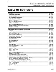
Section <strong>09</strong> PROPULSION SYSTEMSubsection 03 (DRIVE SYSTEM)DRIVE SYSTEM <strong>09</strong>Loctite271125118124710Syntheticgrease1.8 N•m(16 lbf•in)6Right StuffGasket3Syntheticgrease1310F04J47S<strong>09</strong>-03-1
Section <strong>09</strong> PROPULSION SYSTEMSubsection 03 (DRIVE SYSTEM)GENERALJet pump must be removed to replace any componentsof the drive system. Refer to PROPUL-SION SYSTEM <strong>09</strong>-02 for jet pump removal procedure.REMOVALRemove PTO flywheel guard.Large ClampUnfasten large clamp no. 1 of PTO flywheel bootas follows:– Use pliers (P/N 295 000 069).F01J29ATYPICAL1. Locking hooks1F01J0GA– Insert pointed tips of pliers in closing hooks.Small ClampUnfasten small clamp no. 2 of PTO flywheel bootas follows:Use pliers (P/N 295 000 054).F01B1TATo open clamp, place flat side of plier on clampembossment, squeeze and twist plier.F01J2AA1TYPICAL1. Closing hooks– Squeeze pliers to draw hooks together and disengagewindows from locking hooks.F02J0PA<strong>09</strong>-03-2
Section <strong>09</strong> PROPULSION SYSTEMSubsection 03 (DRIVE SYSTEM)Floating Ring and CirclipPush floating ring no. 4 to compress boot no. 7;then, pull out circlip no. 5 from drive shaft groove.F06I06A1. Push floating ring2. Remove circlip1 2Slide floating ring forward completely.Carbon RingLoosen gear clamp no. 12 then pull carbon ringno. 8 from protective boot.Drive Shaft ProtectorIf it is required to remove the protector tube no. 13,squeeze retaining tabs of protector to withdrawtube from through-hull (from the pump side).INSPECTIONAll ModelsDrive Shaft ProtectorInspect drive shaft protector tube no. 13 condition.Check inside of tube and its retaining tabs.Replace tube as necessary.Drive ShaftInspect condition of drive shaft no. 3 and PTO flywheelno. 9 splines.Inspect condition of groove.With your finger nail, feel machined surface ofdrive shaft. If any irregular surface is found, renewdrive shaft.F04I02ADrive ShaftPull out drive shaft no. 3.NOTE: If the drive shaft is jammed into PTO flywheel,a hammer puller can be used to withdrawdrive shaft.Protective BootLoosen gear clamp no. 6 holding protective boot,then carefully pull hose and carbon ring no. 8 fromhull insert.F01I0FA11. Surface condition2. Groove condition3. Splines condition2Excessive deflection could cause vibration anddamage to drive shaft splines, impeller, flywheelor floating ring.Place drive shaft on V-blocks and set-up a dialgauge in center of shaft. Slowly rotate shaft; differencebetween highest and lowest dial gaugereading is deflection. Refer to the following illustration.3<strong>09</strong>-03-3
Section <strong>09</strong> PROPULSION SYSTEMSubsection 03 (DRIVE SYSTEM)Maximum permissible deflection is 0.5 mm (.020 in).Drive Shaft ProtectorApply some Right Stuff Gasket (P/N 293 800 053)on drive shaft protector tube no. 13, as shown inthe next illustration. This will avoid protector vibrations.A1F01J15A21MEASURING DRIVE SHAFT DEFLECTION1. Dial gauge2. V-blocksDamperVisually inspect shape of dampers no. 10 for deformationor other damage.Floating Ring and O-RingInspect condition of O-rings no. 11 and floatingring no. 4 contact surface.1F<strong>09</strong>J0KA1. Apply Right Stuff Gasket hereA. 40 mm (1-9/16 in)Insert drive shaft protector tube in through-hull fittingand properly clip the tabs on the edge of thefitting.NOTE: When inserting drive shaft protector tube,check that embossment is positioned at bottom,as shown in the next photo.2F01I0GA1. O-rings2. Floating ring contact surfaceASSEMBLYAssembly is essentially the reverse of disassemblyprocedure. However, pay particular attentionto the following.F<strong>09</strong>J0MA 11. Embossment positioned at bottom2. Right Stuff Gasket on opposite sideDamperInstall damper no. 10 on drive shaft no. 3.NOTE: Make sure dampers were not left in PTOflywheel or impeller.2<strong>09</strong>-03-4
Section <strong>09</strong> PROPULSION SYSTEMSubsection 03 (DRIVE SYSTEM)Floating Ring and O-RingEnsure both O-rings no. 11 are properly locatedinside floating ring no. 4 grooves.- CAUTIONGrease on the carbon seal, floating ring orO-ring may cause O-ring to dislodge fromthe groove and slide on the drive shaft whichmay allow water leakage. Always wipe offany grease.Drive ShaftInsert drive shaft no. 3 in through-hull fitting buttemporarily keep a gap between shaft end andPTO flywheel no. 9.- CAUTIONDo not apply grease on drive shaft splines.Lubrication will be done later from the PTOflywheel grease fitting.Insert floating ring no. 4 on drive shaft.Engage drive shaft splines in PTO flywheel.NOTE: If shaft is difficult to insert into flywheelboot, a small quantity of grease can be applied IN-SIDE the boot.Rotate shaft to properly index splines. Make sureboot is well-positioned over shaft end.Drive Shaft Boot PreloadThis procedure is required to confirm the properpreload of the boot. Improper preload may allowventilation of propulsion system or water infiltrationin the bilge.Ensure floating ring no. 4 is far enough forward inorder to release all pressure from carbon ring.Measure protective boot free length. Note themeasurement.F00J03ATYPICAL — DO NOT READ THE RULER FROM THEPHOTOGRAPH1. Measuring free length of protective bootA. Measure between carbon ring and through-hull fittingPush floating ring no. 4 farther than groove onshaft.- CAUTIONTake care not to break the O-rings in thefloating ring while inserting the drive shaft.Insert circlip no. 5 in groove of shaft.F06I06A1 A1 21. Push floating ring2. Install circlipMeasure the compressed length (installed parts)of the protective boot (between carbon ring andthrough-hull fitting). Note the measurement.Subtract the compressed length from the freelength.Free length - Compressed length = Difference<strong>09</strong>-03-5
Section <strong>09</strong> PROPULSION SYSTEMSubsection 03 (DRIVE SYSTEM)If the difference is less than 8 mm (5/16 in), aspacer is required (see next paragraph). Otherwise,continue with the installation of clamps (seebelow).Unlock and pull out drive shaft to install one spacerbetween protective boot and hull on throughhullfitting.– Insert pointed tips of pliers first in closing hooks.1F01J2BA1F00J04BTYPICAL1. SpacerReinstall parts and verify compressed length ofboot another time.If everything is within the specification, continuewith the installation of clamps (see below). Otherwise,call your service representative.Large ClampSecure large clamp no. 1 as follows:– Use pliers (P/N 295 000 069) as for removal.– Manually engage holding hook in large window.This is a pre-clamping position only.TYPICAL1. Closing hooks– Squeeze pliers. When both large and small windowsare directly over the 2 locking hooks,press those windows down to engage hooks inwindows.11F02J0IA1. Press to engage hooks in windowsNOTE: At installation, clamp tail should be in oppositedirection of engine rotation.2F01J23APRE-CLAMPING POSITION1. Holding hook2. Large window<strong>09</strong>-03-6
Section <strong>09</strong> PROPULSION SYSTEMSubsection 03 (DRIVE SYSTEM)1LUBRICATIONUsing a grease gun, carefully lubricate PTO flywheelwith synthetic grease (P/N 293 550 010),until boot is just beginning to expand. At thispoint, immediately stop greasing.2F01J23B1. Engine rotation (counterclockwise)2. Tail in opposite directionSmall ClampTo secure small clamp no. 2, place notch side ofplier on clamp embossment and squeeze plier.1F01I0BBF02J0PB1. Squeeze plier<strong>09</strong>-03-7
Section <strong>09</strong> PROPULSION SYSTEMSubsection 04 (REVERSE SYSTEM)REVERSE SYSTEM 0Single-Pump Model4.5 N•m(40 lbf•in)Loctite 242Loctite242Loctite24210 N•m(89 lbf•in)2.7 N•m(24 lbf•in)1Loctite 2427 N•m(62 lbf•in)54269 N•m(80 lbf•in)7F04J48STYPICAL<strong>09</strong>-04-1
Section <strong>09</strong> PROPULSION SYSTEMSubsection 04 (REVERSE SYSTEM)Twin-Pump ModelsLoctite 2424.5 N•m(40 lbf•in)Loctite 24210 N•m(89 lbf•in)Loctite24287 N•m(62 lbf•in)12.7 N•m(24 lbf•in)4Loctite 242Loctite24259 N•m(80 lbf•in)632781.7 N•m(15 lbf•in)1F10J05STYPICAL<strong>09</strong>-04-2
Section <strong>09</strong> PROPULSION SYSTEMSubsection 04 (REVERSE SYSTEM)INSPECTIONCheck all moving parts and bushings for wear,straightness, corrosion and free movement. Replaceparts as required.DISASSEMBLYReverse Gate SupportFor additional information, refer to JET PUMP <strong>09</strong>-02.Detach steering/shifter cables.Detach steering link rod from nozzle (twin-pumpmodels only).Detach reverse gate link rod from RH reverse gate(required even if you are working on LH side ontwin-pump models).F04J1WA 1TYPICAL1. Remove rearmost nutF04J2NA11. DetachRemove reverse gate support no. 2 (with gateno. 1), venturi and nozzle assembly from impellerhousing.NOTE: If you are removing parts on LH side(twin-pump models), the reverse gate link rodno. 3 may be kept with the reverse gate.Reverse Gate Link RodTwin-Pump ModelsTo detach reverse gate link rod no. 3 from LH reversegate no. 1, remove the rearmost nut and rotatelink rod. This gives access to reverse gateretaining screw.F04J1XA 2 1TYPICAL1. Rotate rod2. Remove screwRemove reverse gate to give access to the remainingscrew of link rod.Latching MechanismAll ModelsNote that the latching mechanism is installed onRH reverse gate on twin-pump models.Remove screw no. 4 to detach lever.<strong>09</strong>-04-3
Section <strong>09</strong> PROPULSION SYSTEMSubsection 04 (REVERSE SYSTEM)For installation, install lever no. 5 in a vise and applysome BOMBARDIER LUBE (P/N 293 600 016)in lever hole.Properly position reverse gate and carefully insertroll pin with a hammer.- CAUTIONFailure to properly hold lever in a vise maylead to damages to the reverse gate or thelever.F04J1YACarefully install reverse gate in a vise with a socketunderneath tab holding roll pin.- CAUTIONFailure to properly support tab of roller pinwill lead to damages to the reverse gate.Remove lever no. 5 using a small punch and carefullypushing roll pin no. 6 out.F04J20A 1 21. Hold lever in a vise2. Carefully insert roller pinIf the pawl-stop no. 7 needs to be replaced, drillrivets out with a 4.8 mm (3/16 in) drill bit.21F04J1ZA1. Socket to support tab of roll pin2. Carefully punch roller pin outNOTE: If roll pin cannot be removed this way, asmall cutting disk can be used.F04J21AUSE A 4.8 MM (3/16 IN) DRILL BIT<strong>09</strong>-04-4
Section <strong>09</strong> PROPULSION SYSTEMSubsection 04 (REVERSE SYSTEM)For installation, position pawl-stop as shown.NOTE: When reinstalling reverse link rod, ensurethat anode system wire no. 8 is properly installed,as shown in the next photo.F04J22A 11. Correct position of pawl-stopReverse Gate DeflectorTwin-Pump ModelsIf it has been removed, ensure to reinstall it on theinner side of the reverse gate.F10J06A 11. Install wire ends hereReverse Gate Locking SystemVerification and AdjustmentNOTE: Proceed with RH side on twin-pumpmodels.Fully pull throttle lever (both on twin-pump models)to idle position then pull shifter in reverse position.Ensure reverse gate ear contacts thestopper.F04J23A 1RH REVERSE GATE SHOWN1. On inner side of reverse gateASSEMBLYAll ModelsPrior to assembling moving parts, lubricate withsynthetic grease (P/N 293 550 010).Reinstall steering link rod and reverse link rodno. 3 (twin-pump models only) steering andshifter cables. Refer to STEERING SYSTEM 10-03then look for Alignment. Ensure that steering cableball joints are parallel with cable lever.F04J05A 1TYPICAL — IN REVERSE POSITION1. Must touch<strong>09</strong>-04-5
Section <strong>09</strong> PROPULSION SYSTEMSubsection 04 (REVERSE SYSTEM)Fully push shifter in forward position. A latchingsound should be heard. Try pulling reverse gatedown manually. It must be locked by the latchingmechanism.11F04L7KAF04J06ATYPICAL — IN FORWARD POSITION1. Must be locked when manually pulling downward2. Latching mechanismIf either check fail, readjust cable to meet bothconditions.Shifter Cable AdjustmentUnscrew throttle/shifter controller from boat.- CAUTIONUse a protective mat (P/N 295 000 129) inshifter area when withdrawing it for adjustment.2TYPICAL1. Adjust reverse gate hereShifter Cable ReplacementDetach cable ball joint from cable lever on reversegate then unscrew ball joint from cable.From inside of hull, loosen lock nut. From outsideof hull, pull cable to allow half rings removal.For the other end of cable, remove throttle/shiftercontroller from boat and detach cable from mechanism.At assembly, ensure to properly tighten lock nut.Check watertightness.Adjust as explained above.<strong>09</strong>-04-6
Section <strong>09</strong> PROPULSION SYSTEMSubsection 05 (WEEDLESS SYSTEM)WEEDLESS SYSTEM 014-foot boatsLoctite 242Loctite 2428 N•m(71 lbf•in)Syntheticgrease3Loctite 242Syntheticgrease32 N•m(24 lbf•ft)27 N•m(62 lbf•in)18-foot boats4Loctite 242Adseal 451110 N•m(89 lbf•in)1F04J49S5 N•m(44 lbf•in)Loctite242RightStuffGasket<strong>09</strong>-05-1
Section <strong>09</strong> PROPULSION SYSTEMSubsection 05 (WEEDLESS SYSTEM)REMOVALIntake GrillLower the grill no. 1 and grab it with a hand to feelthe play. If excessive, replace bushings.Detach cable adjuster. Remove retaining screwsto withdraw grill.Pull lever out while holding locking block no. 3 sothat it does not fall.Detach weedless mechanism from body by removingretaining screws.1F04J26A21. Detach cable2. Remove screwsAt assembly, ensure to apply Right Stuff Gasketbetween hull and grill base as well as inside screwholes. Torque screws to 10 N•m (89 lbf•in).Apply Loctite 242 (P/N 293 800 015) on fastenersas shown in exploded view.1F04J27ATYPICAL1. Remove screwsDetach cable(s) from weedless system support.NOTE: Be careful not to drop parts when disassemblingfasteners. There are spacers and washersin the mechanism.2Weedless System MechanismUnlock end of lever no. 2.1°F04J29A 12°1. Detach cable end(s)2. Detach cable from supportF04J28A<strong>09</strong>-05-2
Section <strong>09</strong> PROPULSION SYSTEMSubsection 05 (WEEDLESS SYSTEM)Twin-Pump ModelsDetach cable from back of support.ASSEMBLYAssembly is essentially the reverse of disassembly.However, pay attention to the following.Apply synthetic grease (P/N 293 550 010) to allmoving parts.Apply Loctite 242 (P/N 293 800 015) on threads offasteners as shown in exploded view.Install fasteners as shown below.Torque fasteners as shown in exploded view.F04J2AADetach moving plate from support.INSPECTIONAll ModelsInspect parts for wear, bending or other damage.Replace parts as necessary.Inspect locking block no. 3 for wear/damagewhere shown.F04J2CA 3 2 1PIVOTING POINT OF MOVING PLATE1. Nylon washer2. Spacer3. Steel washerEnsure plate pivots easily after tightening nut.Slightly loosen nut as necessary.1F04J2BA1. Inspect for wear/damage particularly hereF04J2DA 4 3 2 1CABLE ATTACHMENT (LH CABLE ON TWIN-PUMP MODELS)1. Cable end2. Steel washer3. Nylon washer4. Spacer<strong>09</strong>-05-3
Section <strong>09</strong> PROPULSION SYSTEMSubsection 05 (WEEDLESS SYSTEM)Second Cable Attachment(cable for RH pump)Twin-Pump Models1F04J2GAF04J2EA 3 2 1CABLE ATTACHMENT1. Nylon washer2. Steel washer3. Cable endReinstall weedless system support to body.Install lever with its open end as shown.1. Protruding corner hereProperly lock end of lever.Perform cable adjustment as described below.WEEDLESS SYSTEM CABLEREPLACEMENTRemovalLower intake grill no. 1.From underneath hull, detach cable adjuster fromgrill.F04J2FA 11. Open end hereInstall locking block as shown.F04J26B11. Detach cableRemove cable adjuster from cable.<strong>09</strong>-05-4
Section <strong>09</strong> PROPULSION SYSTEMSubsection 05 (WEEDLESS SYSTEM)From inside of bilge, unscrew nut no. 4.F04J2HA 11. Unscrew nutPull cable out.From front storage compartment (RH side onChallenger 1800 models), detach cable fromweedless system support.Twin-Pump ModelsIt is necessary to detach support plate from bodyto allow removal of RH cable.InstallationAll ModelsTape the rear end of the old cable to the end of thenew cable. Pull the old cable from the front to allowthe installation of the new one.NOTE: If necessary, the RH cup holder may be removedto reach the cable.Do not remove the cable housing from the hullneedlessly. If removal has been done, proceedwith the following procedure.Scrape sealant from hull and cable housing.Sand hull surface using a sand paper to completelyremove the sealant.Clean surfaces with acetone or oil-free cleaner(use isopropyl alcohol on plastic parts).Apply Right Stuff Gasket (P/N 293 800 053) on thehull surface taking care to seal around holes andinside holes.Reinstall cable housing to hull as shown.F04J2HB 11. Position of housingGenerously apply Right Stuff Gasket around screwsand particularly on the taper of the screw heads.Secure screws making sure the Right Stuff Gasketmakes a water tight seal around the screws.Assembly is essentially the reverse of disassembly.However, pay attention to the following.Apply sealant Adseal 4511 (P/N 293 800 033) andLoctite 242 on parts and torque fasteners asshown in exploded view.F04J2IA123 4 5PARTS INSTALLATION IN CABLE HOUSING1. Nut2. Half-rings3. Grommet4. Right Stuff Gasket5. Apply synthetic grease on the sliding portion of cable (into grommet)Hand-tighten nut no. 4 until it bottoms then givean additional half a turn.When installing cable adjuster, position it half-wayof the threaded length.When installing cable to weedless system support(in front), position cable housing half-way ofthe threaded length.Perform cable adjustment as described below.<strong>09</strong>-05-5
Section <strong>09</strong> PROPULSION SYSTEMSubsection 05 (WEEDLESS SYSTEM)CABLE ADJUSTMENTAdjustment at Intake GrillA small adjustment can be made here. If it cannotbe reached here, perform it at the lever mechanismas explained below.When weedless lever no. 2 is fully pushed in, thewater intake grill no. 1 must be fully lifted. Ensurethere is no gap.At this point, the weedless system lever must belocked when pulling lever WITHOUT TURNING(contrarily to its normal use). This will validate theoperation of the locking mechanism.If adjustment is required, unscrew cable adjuster,loosen lock nut and turn adjuster as necessary.After adjustment, ensure to apply Loctite 242(P/N 293 800 015) and torque fasteners as shownin exploded view.Adjustment at Weedless LeverMechanismWhen a proper adjustment cannot be reached atintake grill level, adjust cable housing at the weedlesslever mechanism as necessary.1F04J29BF04J2FA 11. Pull lever WITHOUT TURNING1. Adjust cable housing hereValidate adjustment as explained above.F04J2JA 1TYPICAL1. Adjust to remove all gap here<strong>09</strong>-05-6