LS7 Corvette Mechanical Repair Specs (PDF) - Bakes Online
LS7 Corvette Mechanical Repair Specs (PDF) - Bakes Online
LS7 Corvette Mechanical Repair Specs (PDF) - Bakes Online
- No tags were found...

You also want an ePaper? Increase the reach of your titles
YUMPU automatically turns print PDFs into web optimized ePapers that Google loves.
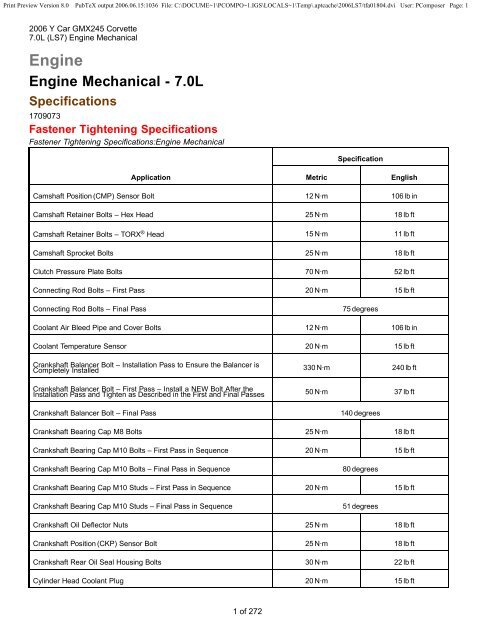
Print Preview Version 8.0 PubTeX output 2006.06.15:1036 File: C:\DOCUME~1\PCOMPO~1.IGS\LOCALS~1\Temp\.aptcache\2006<strong>LS7</strong>/tfa01804.dvi User: PComposer Page: 12006 Y Car GMX245 <strong>Corvette</strong>7.0L (<strong>LS7</strong>) Engine <strong>Mechanical</strong>EngineEngine <strong>Mechanical</strong> - 7.0LSpecifications1709073Fastener Tightening SpecificationsFastener Tightening Specifications:Engine <strong>Mechanical</strong>SpecificationApplication Metric EnglishCamshaft Position (CMP) Sensor Bolt 12 N·m 106 lb inCamshaft Retainer Bolts – Hex Head 25 N·m 18 lb ftCamshaft Retainer Bolts – TORX ® Head 15 N·m 11 lb ftCamshaft Sprocket Bolts 25 N·m 18 lb ftClutch Pressure Plate Bolts 70 N·m 52 lb ftConnecting Rod Bolts – First Pass 20 N·m 15 lb ftConnecting Rod Bolts – Final Pass75 degreesCoolant Air Bleed Pipe and Cover Bolts 12 N·m 106 lb inCoolant Temperature Sensor 20 N·m 15 lb ftCrankshaft Balancer Bolt – Installation Pass to Ensure the Balancer isCompletely Installed 330 N·m 240 lb ftCrankshaft Balancer Bolt – First Pass – Install a NEW Bolt After theInstallation Pass and Tighten as Described in the First and Final Passes 50 N·m 37 lb ftCrankshaft Balancer Bolt – Final Pass140 degreesCrankshaft Bearing Cap M8 Bolts 25 N·m 18 lb ftCrankshaft Bearing Cap M10 Bolts – First Pass in Sequence 20 N·m 15 lb ftCrankshaft Bearing Cap M10 Bolts – Final Pass in Sequence80 degreesCrankshaft Bearing Cap M10 Studs – First Pass in Sequence 20 N·m 15 lb ftCrankshaft Bearing Cap M10 Studs – Final Pass in Sequence51 degreesCrankshaft Oil Deflector Nuts 25 N·m 18 lb ftCrankshaft Position (CKP) Sensor Bolt 25 N·m 18 lb ftCrankshaft Rear Oil Seal Housing Bolts 30 N·m 22 lb ftCylinder Head Coolant Plug 20 N·m 15 lb ft1 of 272
Print Preview Version 8.0 PubTeX output 2006.06.15:1036 File: C:\DOCUME~1\PCOMPO~1.IGS\LOCALS~1\Temp\.aptcache\2006<strong>LS7</strong>/tfa01804.dvi User: PComposer Page: 22006 Y Car GMX245 <strong>Corvette</strong>7.0L (<strong>LS7</strong>) Engine <strong>Mechanical</strong>SpecificationApplication Metric EnglishCylinder Head M8 Bolts – in Sequence 30 N·m 22 lb ftCylinder Head M11 Bolts – First Pass in Sequence 30 N·m 22 lb ftCylinder Head M11 Bolts – Second Pass in SequenceCylinder Head M11 Bolts – Final Pass in Sequence90 degrees70 degreesEngine Block Coolant Drain Hole Plug 60 N·m 44 lb ftEngine Block Coolant Heater 60 N·m 44 lb ftEngine Block Oil Gallery Plugs 60 N·m 44 lb ftEngine Mount Bracket Bolts 50 N·m 37 lb ftEngine Oil Tank Baffle Bolts 10 N·m 89 lb inEngine Oil Tank Bolts 25 N·m 18 lb ftEvaporative (EVAP) Emission Canister Purge Solenoid Valve Bracket Bolt 50 N·m 37 lb ftExhaust Manifold Bolts – First Pass 15 N·m 11 lb ftExhaust Manifold Bolts – Final Pass 20 N·m 15 lb ftExhaust Manifold Heat Shield Bolts 9N·m 80 lb inExhaust Manifold Studs 20 N·m 15 lb ftFlywheel Bolts – First Pass 30 N·m 22 lb ftFlywheel Bolts – Final Pass40 degreesFront Cover Bolts 25 N·m 18 lb ftFuel Injection Fuel Rail Bolts 10 N·m 89 lb inHood Stop Bracket-to-Oil Tank 10 N·m 89 lb inIgnition Coil Bracket-to-Valve Rocker Arm Cover Studs 12 N·m 106 lb inIgnition Coil-to-Bracket Bolts 10 N·m 89 lb inIntake Manifold Bolts – First Pass in Sequence 5N·m 44 lb inIntake Manifold Bolts – Final Pass in Sequence 10 N·m 89 lb inJ 41798 M8 Bolt 25 N·m 18 lb ftJ 41798 M10 Bolts 50 N·m 37 lb ftKnock Sensor Bolts 25 N·m 18 lb ft2 of 272
Print Preview Version 8.0 PubTeX output 2006.06.15:1036 File: C:\DOCUME~1\PCOMPO~1.IGS\LOCALS~1\Temp\.aptcache\2006<strong>LS7</strong>/tfa01804.dvi User: PComposer Page: 32006 Y Car GMX245 <strong>Corvette</strong>7.0L (<strong>LS7</strong>) Engine <strong>Mechanical</strong>SpecificationApplication Metric EnglishOil Cooler Bolts 12 N·m 106 lb inOil Filter 30 N·m 22 lb ftOil Filter Fitting 55 N·m 40 lb ftOil Inlet/Outlet Hose Bracket Bolt 22 N·m 16 lb ftOil Inlet/Outlet Hose-to-Oil Pan Bolts 22 N·m 16 lb ftOil Inlet/Outlet Hose-to-Oil Tank Bolts 22 N·m 16 lb ftOil Pan Closeout Cover Bolt – Left Side 9N·m 80 lb inOil Pan Closeout Cover Bolt – Right Side 9N·m 80 lb inOil Pan Drain Plugs 25 N·m 18 lb ftOil Pan M6 Bolts – Oil Pan-to-Rear Oil Seal Housing 12 N·m 106 lb inOil Pan M8 Bolts – Oil Pan-to-Engine Block and Oil Pan-to-Front Cover 25 N·m 18 lb ftOil Pressure Sensor 35 N·m 26 lb ftOil Pump Cover Bolts 12 N·m 106 lb inOil Pump Relief Valve Plug 12 N·m 106 lb inOil Pump Suction Pipe Bolts 12 N·m 106 lb inOil Pump-to-Engine Block Bolts 25 N·m 18 lb ftOil Tank Middle Bracket Nut 10 N·m 89 lb inOil Tank-to-Frame Bolts 36 N·m 27 lb ftOil Temperature Sensor 20 N·m 15 lb ftSpark Plugs 15 N·m 11 lb ftThrottle Body Bolts 10 N·m 89 lb inTiming Chain Dampener Bolts 25 N·m 18 lb ftValley Cover Bolts 25 N·m 18 lb ftValve Lifter Guide Bolts 12 N·m 106 lb inValve Rocker Arm Bolts 30 N·m 22 lb ftValve Rocker Arm Cover Bolts 12 N·m 106 lb inWater Inlet Housing Bolts 15 N·m 11 lb ft3 of 272
Print Preview Version 8.0 PubTeX output 2006.06.15:1036 File: C:\DOCUME~1\PCOMPO~1.IGS\LOCALS~1\Temp\.aptcache\2006<strong>LS7</strong>/tfa01804.dvi User: PComposer Page: 52006 Y Car GMX245 <strong>Corvette</strong>7.0L (<strong>LS7</strong>) Engine <strong>Mechanical</strong>SpecificationApplication Metric EnglishCylinder Head Deck Surface Flatness – Measured within a 152.4 mm(6.0 in) Area0.11 mm 0.004 inCylinder Head Deck Surface Flatness – Measuring the Overall Lengthof the Block Deck0.22 mm 0.008 inValve Lifter Bore Diameter 21.417–21.443 mm 0.843–0.844 inCamshaftCamshaft End Play 0.025–0.305 mm 0.001–0.012 inCamshaft Journal Diameter 54.99–55.04 mm 2.164–2.166 inCamshaft Journal Out-of-Round 0.008 mm 0.0003 inCamshaftLobeLift–Intake 8.4 mm 0.331 inCamshaft Lobe Lift – Exhaust 8.34 mm 0.328 inCamshaft Runout – Measured at the Intermediate Journals 0.05 mm 0.002 inConnecting RodConnecting Rod Bearing Clearance – Production 0.023–0.065 mm 0.0009–0.0025 inConnecting Rod Bearing Clearance – Service 0.023–0.076 mm 0.0009–0.003 inConnecting Rod Bore Diameter – Bearing End 56.505–56.525 mm 2.224–2.225 inConnecting Rod Bore Diameter – Pin End 23.511–23.519 mm 0.926–0.926 inConnecting Rod Bore Out-of-Round – Bearing End – Production 0.004–0.008 mm 0.00015–0.0003 inConnecting Rod Bore Out-of-Round – Bearing End – Service 0.004–0.008 mm 0.00015–0.0003 inConnecting Rod Side Clearance 0.11–0.51 mm 0.00433–0.02 inCrankshaftConnecting Rod Journal Diameter – Production 53.318–53.338 mm 2.0991–2.0999 inConnecting Rod Journal Diameter – Service 53.308 mm 2.0987 inConnecting Rod Journal Out-of-Round – Production 0.005 mm 0.0002 inConnecting Rod Journal Out-of-Round – Service 0.01 mm 0.0004 inConnecting Rod Journal Taper – Maximum for 1/2 of Journal Length–Production0.005 mm 0.0002 in5 of 272
Print Preview Version 8.0 PubTeX output 2006.06.15:1036 File: C:\DOCUME~1\PCOMPO~1.IGS\LOCALS~1\Temp\.aptcache\2006<strong>LS7</strong>/tfa01804.dvi User: PComposer Page: 72006 Y Car GMX245 <strong>Corvette</strong>7.0L (<strong>LS7</strong>) Engine <strong>Mechanical</strong>SpecificationApplication Metric EnglishSurface Flatness – Measured at Gasket Sealing Surfaces andMeasured Within a 200 mm (7.87 in) Area that Includes 2 RunnerPort Openings0.3 mm 0.118 inLubrication SystemOilCapacity–withFilter 7.57 liters 8.0 quartsOil Capacity – without Filter 7.10 liters 7.5 quartsOil PanOil Pressure – Minimum at 100 C(212F)41 kPa at 1,000 engineRPM124 kPa at 2,000engine RPM165 kPa at 4,000engine RPM6 psig at 1,000 engineRPM18 psig at 2,000 engineRPM24 psig at 4,000 engineRPMFront Cover Alignment – at Oil Pan Surface 0.0–0.5 mm 0.0–0.02 inOil Pan Alignment – to Rear of Engine Block at Transmission BellHousing Mounting Surface0.0–0.1 mm 0.0–0.004 inOil Pump Alignment – at Oil Pan Surface 0.0–0.1 mm 0.0–0.004 inCrankshaft Rear Oil Seal Housing Alignment – at Oil Pan Surface 0.0–0.5 mm 0.0–0.02 inPiston RingsPistonRingEndGap–FirstCompressionRing–MeasuredinCylinder Bore – Production0.22–0.47 mm 0.0087–0.0185 inPistonRingEndGap–FirstCompressionRing–MeasuredinCylinder Bore – Service0.22–0.47 mm 0.0087–0.0185 inPiston Ring End Gap – Second Compression Ring – Measured inCylinder Bore – Production0.40–0.66 mm 0.0157–0.0259 inPiston Ring End Gap – Second Compression Ring – Measured inCylinder Bore – Service0.40–0.66 mm 0.0157–0.0259 inPiston Ring End Gap – Oil Control Ring – Measured in CylinderBore–Production0.25–0.76 mm 0.0098–0.0299 inPiston Ring End Gap – Oil Control Ring – Measured in CylinderBore – Service0.25–0.76 mm 0.0098–0.0299 inPiston Ring to Groove Clearance – First Compression Ring –Production0.030–0.10 mm 0.0012–0.0040 inPiston Ring to Groove Clearance – First Compression Ring – Service 0.030–0.10 mm 0.0012–0.0040 in7 of 272
Print Preview Version 8.0 PubTeX output 2006.06.15:1036 File: C:\DOCUME~1\PCOMPO~1.IGS\LOCALS~1\Temp\.aptcache\2006<strong>LS7</strong>/tfa01804.dvi User: PComposer Page: 82006 Y Car GMX245 <strong>Corvette</strong>7.0L (<strong>LS7</strong>) Engine <strong>Mechanical</strong>SpecificationApplication Metric EnglishPiston Ring to Groove Clearance – Second Compression Ring –Production0.035–0.078 mm 0.0014–0.0031 inPiston Ring to Groove Clearance – Second Compression Ring –Service0.035–0.078 mm 0.0014–0.0031 inPiston Ring to Groove Clearance – Oil Control Ring – Production 0.013–0.201 mm 0.0005–0.0079 inPiston Ring to Groove Clearance – Oil Control Ring – Service 0.013–0.201 mm 0.0005–0.0079 inPistons and PinsPin – Piston Pin Clearance to Piston Pin Bore – Production 0.008–0.023 mm 0.0003–0.0009 inPin – Piston Pin Clearance to Piston Pin Bore – Service 0.008–0.023 mm 0.0003–0.0009 inPin – Piston Pin Diameter 23.497–23.503 mm 0.925–0.925 inPin – Piston Pin Fit in Connecting Rod Bore – Production 0.007–0.02 mm 0.00027–0.00078 inPin – Piston Pin Fit in Connecting Rod Bore – Service 0.007–0.0022 mm 0.00027–0.00086 inPiston – Piston Diameter – Measured Over Skirt Coating 104.758–104.792 mm 4.124–4.126 inPiston–PistontoBoreClearance 0.026 to +0.026 mm 0.001 to +0.001 inValve SystemValves – Face Angle45 degreesValves – Face Width 1.754–2.254 mm 0.069–0.089 inValves – LashNet Lash – No AdjustmentValves – Lift – Intake 15.11 mm 0.595 inValves – Lift – Exhaust 15.01 mm 0.590 inValve Seat – Angle45 degreesValve Seat – Runout 0.05 mm 0.002 inValve Seat – Width – Exhaust 1.7–2.0 mm 0.067–0.079 inValve Seat – Width – Intake 1.25–1.55 mm 0.049–0.061 inValves – Stem Diameter – Intake 7.958–7.9735 mm 0.313–0.314 inValves – Stem Diameter – Exhaust 7.956–7.976 mm 0.313–0.314 in8 of 272
Print Preview Version 8.0 PubTeX output 2006.06.15:1036 File: C:\DOCUME~1\PCOMPO~1.IGS\LOCALS~1\Temp\.aptcache\2006<strong>LS7</strong>/tfa01804.dvi User: PComposer Page: 92006 Y Car GMX245 <strong>Corvette</strong>7.0L (<strong>LS7</strong>) Engine <strong>Mechanical</strong>SpecificationApplication Metric EnglishValves – Stem-to-Guide Clearance – Production – Intake 0.028–0.063 mm 0.001–0.0024 inValves – Stem-to-Guide Clearance – Service – Intake 0.093 mm 0.0037 inValves – Stem-to-Guide Clearance – Production – Exhaust 0.025–0.066 mm 0.001–0.0026 inValves – Stem-to-Guide Clearance – Service – Exhaust 0.093 mm 0.0037 inRocker Arms – Rocker Arm Ratio 1.80:1Valve Springs – Free Length 58.8 mm 2.313 inValve Springs – Installed Height 49.75 mm 1.959 inValveSprings–Load–Closed 450 N at 49.75 mm 101lb at 1.96inValve Springs – Load – Open 1380 N at 34.75 mm 310lb at 1.37inSpecifications1554988Sealers, Adhesives, and LubricantsSealers, Adhesives, and Lubricants:Engine <strong>Mechanical</strong>GM Part NumberApplication Type of Material United States CanadaAll Purpose Parts Cleaner Cleaner 12378553 88900920Coolant Temperature Sensor Threads Sealant 12346004 10953480Cylinder Head Plug Threadlock 12345382 10953489Engine Block Coolant Drain Hole Plug Sealant 12346004 10953480Engine Block Oil Gallery Plug – Front Threadlock 12345382 10953489Engine Block Oil Gallery Plug – Side Sealant 12346004 10953480Engine Degreaser Cleaner 12378482 992878Engine Oil 5W-30Oil–Synthetic 12345610 993193Engine Oil Pressure Sensor Threads Sealant 12346004 10953480Engine Oil Supplement Fluorescent Dye 12345795 10953470Exhaust Manifold Bolts Threadlock 12345493 10953488Flywheel Bolts Threadlock 12345382 109534899 of 272
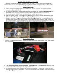
Print Preview Version 8.0 PubTeX output 2006.06.15:1036 File: C:\DOCUME~1\PCOMPO~1.IGS\LOCALS~1\Temp\.aptcache\2006<strong>LS7</strong>/tfa01804.dvi User: PComposer Page: 102006 Y Car GMX245 <strong>Corvette</strong>7.0L (<strong>LS7</strong>) Engine <strong>Mechanical</strong>GM Part NumberApplication Type of Material United States CanadaFuel Injection Fuel Rail Bolts Threadlock 12345382 10953489Ignition Coil Bracket-to-Valve Cover Studs Threadlock 12345382 10953489Ignition Coil-to-Bracket Bolts Threadlock 12345382 10953489Intake Manifold Bolts Threadlock 12345382 10953489Oil Pan Surface at Front Cover and Rear Housing Sealant 12378521 88901148Thread <strong>Repair</strong> Component Cleaner Cleaner 12346139 10953463Thread <strong>Repair</strong> Component Cleaner Cleaner 12377981 10953463Thread <strong>Repair</strong> Cutting Oil Lubricant 1052864 992881Specifications1406762Thread <strong>Repair</strong> SpecificationsEngine Block – Front/Rear Views1402166Engine Block – Front/Rear Views10 of 272
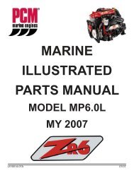
Print Preview Version 8.0 PubTeX output 2006.06.15:1036 File: C:\DOCUME~1\PCOMPO~1.IGS\LOCALS~1\Temp\.aptcache\2006<strong>LS7</strong>/tfa01804.dvi User: PComposer Page: 112006 Y Car GMX245 <strong>Corvette</strong>7.0L (<strong>LS7</strong>) Engine <strong>Mechanical</strong>HoleThreadSize Insert DrillCounterboreTool Tap DriverDrill Depth– Maximummm (in)Tap Depth–Maximummm (in)J 42385-1 M8 x1.25 210 206 207 208 209 22.5 (0.885) 17.5 (0.688)2 M10 x1.5 215 211 212 213 214 27.5 (1.08) 22.0 (0.866)3 M10 x1.5 215 211 212 213 214 Thru Thru4 M8 x1.25 210 206 207 208 209 Thru Thru5 M10 x1.5 215 211 212 213 214 25.0 (0.984) 19.5 (0.767)6 M10 x1.5 215 211 212 213 214 32.5 (1.279) 25.0 (0.984)7 M10 x1.5 215 211 212 213 214 Thru ThruBolt hole 6 is drilled and tapped for aluminum block applications only.Engine Block – Left/Right Side Views1402160Engine Block – Left/Right Side Views11 of 272
Print Preview Version 8.0 PubTeX output 2006.06.15:1036 File: C:\DOCUME~1\PCOMPO~1.IGS\LOCALS~1\Temp\.aptcache\2006<strong>LS7</strong>/tfa01804.dvi User: PComposer Page: 122006 Y Car GMX245 <strong>Corvette</strong>7.0L (<strong>LS7</strong>) Engine <strong>Mechanical</strong>HoleThreadSize Insert DrillCounterboreTool Tap DriverDrill Depth– Maximummm (in)Tap Depth–Maximummm (in)J 42385-1 M8 x1.25 210 206 207 208 209 22.5 (0.885) 17.5 (0.688)2 M8 x1.25 210 206 207 208 209 28.5 (1.122) 23.0 (0.905)3 M8 x1.25 210 206 207 208 209 21.5 (0.846) 16.0 (0.629)4 M10 x1.25 215 211 212 213 214 29.0 (1.141) 23.0 (0.905)5 M10 x1.5 215 211 212 213 214 27.0 (1.062) 21.5 (0.846)6 M16 x1.5 N/A N/A N/A N/A N/A N/A N/A7 M11 x2.0 108 105 N/A 106 107 69.0 (2.72) 60.0 (2.36)8 M28 x1.25 N/A N/A N/A N/A N/A N/A N/ABolt hole 7 has a 30 mm (1.18 in) counterbore included in the 69.0 mm (2.72 in) drill depth. Use sleeve J 42385-315 with thedrill and tap.Engine Block – Top/Bottom Views12 of 272
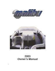
Print Preview Version 8.0 PubTeX output 2006.06.15:1036 File: C:\DOCUME~1\PCOMPO~1.IGS\LOCALS~1\Temp\.aptcache\2006<strong>LS7</strong>/tfa01804.dvi User: PComposer Page: 132006 Y Car GMX245 <strong>Corvette</strong>7.0L (<strong>LS7</strong>) Engine <strong>Mechanical</strong>1402164Engine Block – Top/Bottom ViewsHoleThreadSize Insert DrillCounterboreTool Tap DriverDrill Depth– Maximummm (in)Tap Depth–Maximummm (in)J 42385-1 M8 x1.25 210 206 207 208 209 22.5 (0.885) 17.5 (0.688)2 M10 x1.5 215 211 212 213 214 42.5 (1.67) 37.0 (1.45)3 M10 x2.0 104 101 N/A 102 103 31.0 (1.22) 25.5 (1.0)4 M10 x2.0 104 101 N/A 102 103 53.5 (2.10) 44.0 (1.73)5 M8 x1.25 210 206 207 208 209 26.5 (1.043) 19.0 (0.748)• Bolt hole 2 has an 11.5 mm (0.452 in) counterbore included in the 42.5 mm (1.67 in) drill depth. Use sleeve J 42385-311withthedrillandtap.• Bolt hole 3 has a 1.5 mm (0.059 in) counterbore included in the 31.0 mm (1.22 in) drill depth. Use sleeve J 42385-316withthedrillandtap.• Bolt hole 4 has a 20.5 mm (0.807 in) counterbore included in the 53.5 mm (2.10 in) drill depth.Cylinder Head – Top/End Views13 of 272
Print Preview Version 8.0 PubTeX output 2006.06.15:1036 File: C:\DOCUME~1\PCOMPO~1.IGS\LOCALS~1\Temp\.aptcache\2006<strong>LS7</strong>/tfa01804.dvi User: PComposer Page: 142006 Y Car GMX245 <strong>Corvette</strong>7.0L (<strong>LS7</strong>) Engine <strong>Mechanical</strong>1402168Cylinder Head – Top/End ViewsHoleThreadSize Insert DrillCounterboreTool Tap DriverDrill Depth– Maximummm (in)Tap Depth–Maximummm (in)J 42385-1 M8 x1.25 210 206 207 208 209 26.5 (1.04) 19.0 (0.784)2 M6 x 1.0 205 201 202 203 204 20.05 (0.789) 16.05 (0.632)3 M10 x1.5 215 211 212 213 214 28.0 (1.10) 20.0 (0.787)4 M6 x 1.0 205 201 202 203 204 22.5 (0.885) 15.0 (0.688)Cylinder Head – Intake/Exhaust Side Views14 of 272
Print Preview Version 8.0 PubTeX output 2006.06.15:1036 File: C:\DOCUME~1\PCOMPO~1.IGS\LOCALS~1\Temp\.aptcache\2006<strong>LS7</strong>/tfa01804.dvi User: PComposer Page: 152006 Y Car GMX245 <strong>Corvette</strong>7.0L (<strong>LS7</strong>) Engine <strong>Mechanical</strong>1402171Cylinder Head – Intake/Exhaust Side ViewsHoleThreadSize Insert DrillCounterboreTool Tap DriverDrill Depth– Maximummm (in)Tap Depth–Maximummm (in)J 42385-1 M6 x 1.0 205 201 202 203 204 Thru Thru2 M10 x1.5 215 211 212 213 214 28.0 (1.10) 20.0 (0.787)3 M8 x1.25 210 206 207 208 209 21.0 (0.826) 16.0 (0.629)4 M14 x1.25 N/A N/A N/A N/A N/A N/A N/A5 M12 x1.5 N/A N/A N/A N/A N/A N/A N/AComponent Locator1556658Disassembled ViewsFigure 1556644Intake Manifold/Upper Engine15 of 272
Print Preview Version 8.0 PubTeX output 2006.06.15:1036 File: C:\DOCUME~1\PCOMPO~1.IGS\LOCALS~1\Temp\.aptcache\2006<strong>LS7</strong>/tfa01804.dvi User: PComposer Page: 162006 Y Car GMX245 <strong>Corvette</strong>7.0L (<strong>LS7</strong>) Engine <strong>Mechanical</strong>1552417100. Engine Block307. Engine Coolant Air Bleed Pipe308. Engine Coolant Air Bleed Pipe Seal308. Engine Coolant Air Bleed Pipe Seal309. Bolt312. Bolt313. Engine Coolant Air Bleed Pipe Hole Cover500. Intake Manifold506. Bolt508. Throttle Body509. Throttle Body Seal510. Fuel Rail Assembly – Multi-Port511. Bolt512. Bolt513. Intake Manifold Seal514. Intake Manifold Gasket537. Engine Block Valley Cover High Pressure Port Seal538. Bolt555. Engine Block Valley Cover16 of 272
Print Preview Version 8.0 PubTeX output 2006.06.15:1036 File: C:\DOCUME~1\PCOMPO~1.IGS\LOCALS~1\Temp\.aptcache\2006<strong>LS7</strong>/tfa01804.dvi User: PComposer Page: 172006 Y Car GMX245 <strong>Corvette</strong>7.0L (<strong>LS7</strong>) Engine <strong>Mechanical</strong>556. Engine Block Valley Cover Gasket557. Fuel Injection Fuel Rail Bracket700. Positive Crankcase Ventilation (PCV) Tube – Fresh Air706. Engine Oil Pressure Sensor707. Engine Oil Pressure Sensor Seal712. Fuel Injection Fuel Rail Stop712. Fuel Injection Fuel Rail Stop714. Manifold Absolute Pressure (MAP) Sensor715. MAP Sensor Seal716. PCV Hose – Dirty Air729. Evaporative (EVAP) Emission Canister Purge Tube730. EVAP Canister Purge Solenoid Valve731. EVAP Service Valve Cap734. EVAP Service Valve735. EVAP Canister Purge Tube740. EVAP Canister Purge Tube Clip741. EVAP Canister Purge Solenoid Valve Bracket742. BoltFigure 1556646Cylinder Head/Upper Engine17 of 272
Print Preview Version 8.0 PubTeX output 2006.06.15:1036 File: C:\DOCUME~1\PCOMPO~1.IGS\LOCALS~1\Temp\.aptcache\2006<strong>LS7</strong>/tfa01804.dvi User: PComposer Page: 182006 Y Car GMX245 <strong>Corvette</strong>7.0L (<strong>LS7</strong>) Engine <strong>Mechanical</strong>1552418100. Engine Block209. Valve Lifter210. Valve Lifter Guide211. Bolt212. Valve Pushrod213. Valve Rocker Arm214. Bolt217. Cylinder Head Gasket218. Cylinder Head220. Cylinder Head Bolt – M11221. Cylinder Head Bolt – M8222. Valve Stem Oil Seal223. Valve Spring224. Valve Spring Cap225. Valve Stem Key227. Intake Valve228. Exhaust Valve229. Cylinder Head Plug230. Cylinder Head Locating Pin18 of 272
Print Preview Version 8.0 PubTeX output 2006.06.15:1036 File: C:\DOCUME~1\PCOMPO~1.IGS\LOCALS~1\Temp\.aptcache\2006<strong>LS7</strong>/tfa01804.dvi User: PComposer Page: 192006 Y Car GMX245 <strong>Corvette</strong>7.0L (<strong>LS7</strong>) Engine <strong>Mechanical</strong>234. Valve Rocker Arm Wear Pad – Intake Valve424. Oil Cap450. Oil Cap O-Ring Seal504. Valve Rocker Arm Cover Gasket504. Valve Rocker Arm Cover Gasket505. Valve Rocker Arm Cover505. Valve Rocker Arm Cover515. Bolt Grommet516. Bolt559. Engine Cover Stud600. Exhaust Manifold601. Exhaust Manifold Gasket602. Bolt603. Exhaust Manifold Heat Shield604. Bolt605. Stud700. Positive Crankcase Ventilation (PCV) Tube – Fresh Air719. Ignition Coil Bracket720. Stud721. Ignition Coil Wire Harness Assembly722. Ignition Coil723. Bolt724. Spark Plug Wire725. Coolant Temperature Sensor726. Spark PlugFigure 1556647Front of Engine19 of 272
Print Preview Version 8.0 PubTeX output 2006.06.15:1036 File: C:\DOCUME~1\PCOMPO~1.IGS\LOCALS~1\Temp\.aptcache\2006<strong>LS7</strong>/tfa01804.dvi User: PComposer Page: 202006 Y Car GMX245 <strong>Corvette</strong>7.0L (<strong>LS7</strong>) Engine <strong>Mechanical</strong>1552419100. Engine Block138. Crankshaft Balancer139. Bolt140. Crankshaft Front Oil Seal143. Balancer Weight – Crankshaft Balancer200. Camshaft201. Camshaft Bearings202. Camshaft Sprocket Locating Pin203. Camshaft Retainer204. Bolt205. Camshaft Sprocket206. Bolt207. Crankshaft Sprocket208. Timing Chain231. Bolt232. Timing Chain Dampener233. Crankshaft Balancer Washer300. Water Pump301. Bolt20 of 272
Print Preview Version 8.0 PubTeX output 2006.06.15:1036 File: C:\DOCUME~1\PCOMPO~1.IGS\LOCALS~1\Temp\.aptcache\2006<strong>LS7</strong>/tfa01804.dvi User: PComposer Page: 212006 Y Car GMX245 <strong>Corvette</strong>7.0L (<strong>LS7</strong>) Engine <strong>Mechanical</strong>302. Bolt303. Water Inlet Housing304. Water Inlet Seal305. Engine Coolant Thermostat306. Water Pump Gasket408. Bolt409. Oil Pump Cover410. Oil Pump Gear – Drive410. Oil Pump Gear – Drive411. Bolt412. Oil Pump Gear – Driven412. Oil Pump Gear – Driven413. Oil Pump Housing – Primary414. Oil Pressure Relief Valve415. Oil Pressure Relief Valve Spring416. Oil Pressure Relief Valve Plug456. Oil Pump Housing – Secondary501. Bolt502. Engine Front Cover503. Engine Front Cover Gasket703. Camshaft Position (CMP) Sensor704. CMP Sensor Seal705. CMP Sensor Bolt737. CMP Sensor Wire HarnessFigure 1556648Rear of Engine1552421100. Engine Block123. Transmission Pilot Bearing133. Bolt21 of 272
Print Preview Version 8.0 PubTeX output 2006.06.15:1036 File: C:\DOCUME~1\PCOMPO~1.IGS\LOCALS~1\Temp\.aptcache\2006<strong>LS7</strong>/tfa01804.dvi User: PComposer Page: 222006 Y Car GMX245 <strong>Corvette</strong>7.0L (<strong>LS7</strong>) Engine <strong>Mechanical</strong>134. Flywheel – Manual Transmission135. Clutch Drive Plate – Manual Transmission136. Clutch Pressure Plate – Manual Transmission137. Bolt141. Crankshaft Rear Oil Seal142. Clutch Pressure Plate Locating Pin – Manual Transmission144. Balance Weight – Flywheel517. Bolt518. Crankshaft Rear Oil Seal Housing519. Crankshaft Rear Oil Seal Housing GasketFigure 1556651Lower Engine Assembly1552424100. Engine Block102. Bolt103. Connecting Rod Cap104. Connecting Rod Bearing105. Connecting Rod106. Piston Pin107. Piston108. Piston Ring Set22 of 272
Print Preview Version 8.0 PubTeX output 2006.06.15:1036 File: C:\DOCUME~1\PCOMPO~1.IGS\LOCALS~1\Temp\.aptcache\2006<strong>LS7</strong>/tfa01804.dvi User: PComposer Page: 232006 Y Car GMX245 <strong>Corvette</strong>7.0L (<strong>LS7</strong>) Engine <strong>Mechanical</strong>109. Piston Pin Retainer120. Crankshaft Bearing – Thrust120. Crankshaft Bearing – Thrust121. Crankshaft Bearing121. Crankshaft Bearing122. Crankshaft Sprocket Key123. Transmission Pilot Bearing124. Crankshaft126. Crankshaft Bearing Cap127. Bolt – M8128. Stud – M10129. Bolt – M10149. Crankshaft Hole Plug150. Crankshaft Bearing Cap Locating Pin151. Connecting Rod Cap Locating Pin400. Oil Pan401. Engine Cover – Right402. Bolt403. Crankshaft Oil Deflector Nut405. Bolt406. Oil Pump Suction Pipe Gasket407. Oil Pump Screen425. Crankshaft Oil Deflector426. Oil Pan Gasket429. Oil Pan Drain Plug Seal – O-Ring429. Oil Pan Drain Plug Seal – O-Ring430. Oil Pan Drain Plug430. Oil Pan Drain Plug431. Oil Pan Cover – Left432. Bolt437. Oil Filter438. Oil Filter Fitting439. Bolt – M8453. Bolt – M6457. Oil Pan Hole PlugFigure 1556652Engine Block Plugs/Sensors23 of 272
Print Preview Version 8.0 PubTeX output 2006.06.15:1036 File: C:\DOCUME~1\PCOMPO~1.IGS\LOCALS~1\Temp\.aptcache\2006<strong>LS7</strong>/tfa01804.dvi User: PComposer Page: 242006 Y Car GMX245 <strong>Corvette</strong>7.0L (<strong>LS7</strong>) Engine <strong>Mechanical</strong>1401949100. Engine Block100. Engine Block101. Engine Block Oil Gallery Plug – Front110. Engine Block Oil Gallery Plug Seal111. Engine Block Oil Gallery Plug – Rear112. Engine Block Oil Gallery Plug – Side113. Engine Block Oil Gallery Plug Seal114. Engine Block Coolant Heater115. Engine Block Coolant Heater Seal116. Engine Block Oil Gallery Plug – Side117. Engine Block Oil Gallery Plug Seal130. Transmission Locating Pin145. Engine Block Coolant Drain Hole Plug Seal146. Engine Block Coolant Drain Hole Plug – Side701. Crankshaft Position (CKP) Sensor702. CKP Sensor Seal718. Knock Sensor718. Knock Sensor24 of 272
Print Preview Version 8.0 PubTeX output 2006.06.15:1036 File: C:\DOCUME~1\PCOMPO~1.IGS\LOCALS~1\Temp\.aptcache\2006<strong>LS7</strong>/tfa01804.dvi User: PComposer Page: 252006 Y Car GMX245 <strong>Corvette</strong>7.0L (<strong>LS7</strong>) Engine <strong>Mechanical</strong>739. Bolt739. Bolt750. CKP Sensor BoltFigure 1556654Oil Pump Assembly1552425408. Bolt409. Oil Pump Cover410. Oil Pump Gear – Drive410. Oil Pump Gear – Drive412. Oil Pump Gear – Driven412. Oil Pump Gear – Driven413. Oil Pump Housing – Primary414. Oil Pressure Relief Valve415. Oil Pressure Relief Valve Spring416. Oil Pressure Relief Valve Plug456. Oil Pump Housing – SecondaryFigure 1831010Engine Oil Tank Assembly25 of 272
Print Preview Version 8.0 PubTeX output 2006.06.15:1036 File: C:\DOCUME~1\PCOMPO~1.IGS\LOCALS~1\Temp\.aptcache\2006<strong>LS7</strong>/tfa01804.dvi User: PComposer Page: 262006 Y Car GMX245 <strong>Corvette</strong>7.0L (<strong>LS7</strong>) Engine <strong>Mechanical</strong>18304221. Oil Level Indicator2. OilFillCap3. O-ring4. Tube5. Engine Oil Tank – Bottom6. Engine Oil Temperature Sensor7. Bracket8. Bolt9. Bolt10. Bracket11. Screen12. O-ring13. Bolt14. Baffle15. Engine Oil Tank – Top16. Bolt/Stud17. BoltComponent Locator26 of 272
Print Preview Version 8.0 PubTeX output 2006.06.15:1036 File: C:\DOCUME~1\PCOMPO~1.IGS\LOCALS~1\Temp\.aptcache\2006<strong>LS7</strong>/tfa01804.dvi User: PComposer Page: 272006 Y Car GMX245 <strong>Corvette</strong>7.0L (<strong>LS7</strong>) Engine <strong>Mechanical</strong>1554991Engine Identification1552521The vehicle identification number (VIN) is located on the left side rear of the engine block (1) and is typically a 9 digitnumber stamped or laser-etched onto the engine at the vehicle assembly plant.• The first digit identifies the division.• The second digit identifies the model year.• The third digit identifies the assembly plant.• The fourth through ninth digits are the last 6 digits of the VIN.Diagnostic Information and Procedures1554993Diagnostic Starting Point - Engine <strong>Mechanical</strong>Diagnostic Starting Point:Engine <strong>Mechanical</strong> - 4.8L, 5.3L, and 6.0LBegin the system diagnosis by reviewing the Disassembled Views , Engine Component Description , Lubrication Description,andDrive Belt System Description . Reviewing the description and operation information will help you determine thecorrect symptom diagnostic procedure when a malfunction exists. Reviewing the description and operation informationwill also help you determine if the condition described by the customer is normal operation. Refer to Symptoms - Engine<strong>Mechanical</strong> in order to identify the correct procedure for diagnosing the system and where the procedure is located.Diagnostic Information and Procedures1554995Symptoms - Engine <strong>Mechanical</strong>Symptoms:Engine <strong>Mechanical</strong> - 4.8L, 5.3L, and 6.0LStrategy Based Diagnostics1. Perform the Diagnostic System Check - Vehicle before using the symptom tables, if applicable.2. Review the system operations in order to familiarize yourself with the system functions. Refer to DisassembledViews , Engine Component Description , Lubrication Description ,andDrive Belt System Description .All diagnosis on a vehicle should follow a logical process. Strategy based diagnostics is a uniform approach for repairing allsystems. The diagnostic flow may always be used in order to resolve a system condition. The diagnostic flow is the placeto start when repairs are necessary. For a detailed explanation, refer to Strategy Based Diagnosis .27 of 272
Print Preview Version 8.0 PubTeX output 2006.06.15:1036 File: C:\DOCUME~1\PCOMPO~1.IGS\LOCALS~1\Temp\.aptcache\2006<strong>LS7</strong>/tfa01804.dvi User: PComposer Page: 282006 Y Car GMX245 <strong>Corvette</strong>7.0L (<strong>LS7</strong>) Engine <strong>Mechanical</strong>Visual/Physical Inspection• Inspect for aftermarket devices which could affect the operation of the engine. Refer to Checking AftermarketAccessories .• Inspect the easily accessible or visible system components for obvious damage or conditions which could causethe symptom.• Inspect for the correct oil level, proper oil viscosity, and correct oil filter.• Verify the exact operating conditions under which the concern exists. Note factors such as engine RPM, ambienttemperature, engine temperature, amount of engine warm-up time, and other specifics.• Compare the engine sounds, if applicable, to a known good engine and make sure you are not trying to correcta normal condition.IntermittentTest the vehicle under the same conditions that the customer reported in order to verify the system is operating properly.Symptom ListRefer to a symptom diagnostic procedure from the following list in order to diagnose the symptom:• Base Engine Misfire without Internal Engine Noises• Base Engine Misfire with Abnormal Internal Lower Engine Noises• Base Engine Misfire with Abnormal Valve Train Noise• Base Engine Misfire with Coolant Consumption• Base Engine Misfire with Excessive Oil Consumption• EngineNoiseonStart-Up,butOnlyLastingaFewSeconds• Upper Engine Noise, Regardless of Engine Speed• Lower Engine Noise, Regardless of Engine Speed• Engine Noise Under Load• Engine Will Not Crank - Crankshaft Will Not Rotate• Coolant in Combustion Chamber• Coolant in Engine Oil• Engine Compression Test• Cylinder Leakage Test• Oil Consumption Diagnosis• Oil Pressure Diagnosis and Testing• Oil Leak Diagnosis• Crankcase Ventilation System Inspection/Diagnosis• Drive Belt Chirping Diagnosis• Drive Belt Squeal Diagnosis• Drive Belt Whine Diagnosis• Drive Belt Rumbling Diagnosis• Drive Belt Vibration Diagnosis• Drive Belt Falls Off Diagnosis• Drive Belt Excessive Wear Diagnosis• Drive Belt Tensioner DiagnosisDiagnostic Information and Procedures1555001Base Engine Misfire without Internal Engine NoisesBase Engine Misfire without Internal Engine Noises:Engine <strong>Mechanical</strong> - 4.8L, 5.3L, and 6.0L28 of 272
Print Preview Version 8.0 PubTeX output 2006.06.15:1036 File: C:\DOCUME~1\PCOMPO~1.IGS\LOCALS~1\Temp\.aptcache\2006<strong>LS7</strong>/tfa01804.dvi User: PComposer Page: 292006 Y Car GMX245 <strong>Corvette</strong>7.0L (<strong>LS7</strong>) Engine <strong>Mechanical</strong>CauseFuel injector harness connectors are connected to the incorrectfuel injectors/cylinders.Abnormalities, such as severe cracking, bumps, or missingareas in the accessory drive beltAbnormalities in the accessory drive system and/orcomponents may cause engine RPM variations and lead to amisfire DTC. A misfire code may be present without an actualmisfire condition.Worn, damaged, or mis-aligned accessory drive componentsor excessive pulley runoutMayleadtoamisfireDTC.A misfire code may be present without an actual misfirecondition.Loose or improperly installed flywheel or crankshaft balancerA misfire code may be present without an actual misfirecondition.Restricted exhaust systemA severe restriction in the exhaust flow can cause significantloss of engine performance and may set a DTC. Possiblecauses of restrictions include collapsed or dented pipes orplugged mufflers and/or catalytic converters.Improperly installed or damaged vacuum hosesImproper sealing between the intake manifold and cylinderheads or throttle bodyImproperly installed or damaged MAP sensorThe seal of the MAP sensor should not be torn or damaged.Worn or loose rocker armsThe rocker arm bearing end caps and/or needle bearingsshould be intact and the rocker arm in the proper position.Worn or bent valve pushrodsStuck valvesCarbon buildup on the valve stem can cause the valve not toclose properly.Excessively worn or mis-aligned timing chainWorn camshaft lobesExcessive oil pressureA lubrication system with excessive oil pressure may lead toexcessive valve lifter pump-up and loss of compression.CorrectionRelocate the fuel injector harness connectors, as necessary.Replace the drive belt. Refer to Drive Belt Replacement -Accessory .Inspect the components and repair or replace, as required.<strong>Repair</strong> or replace the flywheel and/or balancer, as required.Refer to Engine Flywheel Replacement or Crankshaft BalancerReplacement .<strong>Repair</strong> or replace, as required.<strong>Repair</strong> or replace, as required.Replace the intake manifold, gaskets, cylinder heads, and/orthrottle body, as required.<strong>Repair</strong> or replace the MAP sensor, as required.Replace the valve rocker arms, as required.• Replace the pushrods.• Inspect the top of the pistons for valve contact. If thetop of the piston shows valve contact, replace the piston andpin assembly.<strong>Repair</strong> or replace, as required.Replace the timing chain and sprockets, as required.Replace the camshaft and valve lifters.1. Perform an oil pressure test. Refer to Oil PressureDiagnosis and Testing .2. <strong>Repair</strong> or replace the oil pump, as required.29 of 272
Print Preview Version 8.0 PubTeX output 2006.06.15:1036 File: C:\DOCUME~1\PCOMPO~1.IGS\LOCALS~1\Temp\.aptcache\2006<strong>LS7</strong>/tfa01804.dvi User: PComposer Page: 302006 Y Car GMX245 <strong>Corvette</strong>7.0L (<strong>LS7</strong>) Engine <strong>Mechanical</strong>CauseFaulty cylinder head gaskets and/or cracking or other damageto the cylinder heads and engine block cooling systempassagesCoolant consumption may or may not cause the engine tooverheat.Worn piston ringsOil consumption may or may not cause the engine to misfire.A damaged crankshaft reluctor wheelA damaged crankshaft reluctor wheel can result in differentsymptoms depending on the severity and location of thedamage.Correction• Inspect for spark plugs saturated by coolant. Refer toSpark Plug Inspection .• Inspect the cylinder heads, engine block, and/or headgaskets. Refer to Coolant in Combustion Chamber .• <strong>Repair</strong> or replace, as required.• Inspect the spark plugs for oil deposits. Refer to SparkPlug Inspection .• Inspect the cylinders for a loss of compression. Referto Engine Compression Test .• Perform cylinder leak down and compression testing toidentify the cause. Refer to Cylinder Leakage Test .• <strong>Repair</strong> or replace, as required.Replace the sensor and/or crankshaft, as required.• Systems with electronic communications, DIS, or coilper cylinder, and severe reluctor ring damage may exhibitperiodic loss of crankshaft position, stop delivering a signal,and then sync the crankshaft position.• Systems with electronic communication, DIS, or coil percylinder, and slight reluctor ring damage may exhibit no lossof crankshaft position and no misfire may occur. However, aP0300 DTC may be set.• Systems with mechanical communications, high voltageswitch, and severe reluctor ring damage may cause additionalpulses and effect fuel and spark delivery to the point ofgenerating a DTC P0300 or P0336.Diagnostic Information and Procedures1555002Base Engine Misfire with Abnormal Internal Lower Engine NoisesBase Engine Misfire with:Abnormal Internal Lower Engine Noises:Engine <strong>Mechanical</strong> - 4.8L, 5.3L, and 6.0LCauseAbnormalities, such as severe cracking, bumps or missingareas in the accessory drive beltAbnormalities in the accessory drive system and/orcomponents may cause engine RPM variations, noises similarto a faulty lower engine and also lead to a misfire condition. Amisfire code may be present without an actual misfire condition.Worn, damaged, or mis-aligned accessory drive componentsor excessive pulley runoutA misfire code may be present without an actual misfirecondition.Loose or improperly installed flywheel or crankshaft balancerA misfire code may be present without an actual misfirecondition.CorrectionReplace the drive belt. Refer to Drive Belt Replacement -Accessory .1. Inspect the components.2. <strong>Repair</strong> or replace, as required.<strong>Repair</strong> or replace the flywheel and/or balancer, as required.Refer to Engine Flywheel Replacement or Crankshaft BalancerReplacement .30 of 272
Print Preview Version 8.0 PubTeX output 2006.06.15:1036 File: C:\DOCUME~1\PCOMPO~1.IGS\LOCALS~1\Temp\.aptcache\2006<strong>LS7</strong>/tfa01804.dvi User: PComposer Page: 312006 Y Car GMX245 <strong>Corvette</strong>7.0L (<strong>LS7</strong>) Engine <strong>Mechanical</strong>CauseWorn piston ringsOil consumption may or may not cause the engine to misfire.Correction• Inspect the spark plugs for oil deposits. Refer to SparkPlug Inspection .• Inspect the cylinders for a loss of compression. Referto Engine Compression Test .• Perform cylinder leak down and compression testing todetermine the cause. Refer to Cylinder Leakage Test .• <strong>Repair</strong> or replace, as required.Worn crankshaft thrust bearingsSeverely worn thrust surfaces on the crankshaft and/or thrustbearing may permit fore and aft movement of the crankshaftand create a DTC without an actual misfire condition.Diagnostic Information and ProceduresReplace the crankshaft and bearings, as required.1555011Base Engine Misfire with Abnormal Valve Train NoiseBase Engine Misfire with:Abnormal Valve Train Noise:Engine <strong>Mechanical</strong> - 4.8L, 5.3L, and 6.0LCauseWorn or loose rocker armsThe rocker arm bearing end caps and/or needle bearingsshould be intact within the rocker arm assembly.Worn or bent valve pushrodsStuck valvesCarbon buildup on the valve stem can cause the valve not toclose properly.Excessively worn or mis-aligned timing chainWorn camshaft lobesCorrectionReplace the valve rocker arms, as required.• Replace the pushrods.• Inspect the top of the pistons for valve contact. If thetop of the piston shows valve contact, replace the piston andpin assembly.<strong>Repair</strong> or replace, as required.Replace the timing chain and sprockets, as required.Replace the camshaft and valve lifters.Sticking liftersDiagnostic Information and ProceduresReplace, as required.1555012Base Engine Misfire with Coolant ConsumptionBase Engine Misfire with:Coolant Consumption:Engine <strong>Mechanical</strong> - 4.8L, 5.3L, and 6.0L31 of 272
Print Preview Version 8.0 PubTeX output 2006.06.15:1036 File: C:\DOCUME~1\PCOMPO~1.IGS\LOCALS~1\Temp\.aptcache\2006<strong>LS7</strong>/tfa01804.dvi User: PComposer Page: 322006 Y Car GMX245 <strong>Corvette</strong>7.0L (<strong>LS7</strong>) Engine <strong>Mechanical</strong>CauseCorrectionFaulty cylinder head gaskets and/or cracking or other damageto the cylinder heads and engine block cooling systempassagesCoolant consumption may or may not cause the engine tooverheat.Diagnostic Information and Procedures• Inspect for spark plugs saturated by coolant. Refer toSpark Plug Inspection .• Perform a cylinder leak down test. Refer to CylinderLeakage Test .• Inspect the cylinder heads and engine block for damageto the coolant passages and/or a faulty head gasket. Refer toCoolant in Combustion Chamber .• <strong>Repair</strong> or replace, as required.1555013Base Engine Misfire with Excessive Oil ConsumptionBase Engine Misfire with:Excessive Oil Consumption:Engine <strong>Mechanical</strong> - 4.8L, 5.3L, and 6.0LCauseCorrectionWorn valves, valve guides and/or valve stem oil seals 1. Inspect the spark plugs for oil deposits. Refer to SparkPlug Inspection .2. <strong>Repair</strong> or replace, as required.Worn piston ringsOil consumption may or may not cause the engine to misfire.1. Inspect the spark plugs for oil deposits. Refer to SparkPlug Inspection .2. Inspect the cylinders for a loss of compression. Referto Engine Compression Test .3. Perform cylinder leak down and compression testing todetermine the cause. Refer to Cylinder Leakage Test .4. <strong>Repair</strong> or replace, as required.Diagnostic Information and Procedures1555014Engine Noise on Start-Up, but Only Lasting a Few SecondsEngine Noise:On Start-Up, but Only Lasting a Few Seconds:Engine <strong>Mechanical</strong> - 4.8L, 5.3L, and 6.0LCauseIncorrect oil filter without anti-drainback featureInstall the correct oil filter.CorrectionIncorrect oil viscosity 1. Drain the oil.2. Install the correct viscosity oil.High valve lifter leak down rateReplace the lifters, as required.Worn crankshaft thrust bearing 1. Check the crankshaft end play.2. Inspect the thrust bearing and crankshaft.3. <strong>Repair</strong> or replace, as required.Faulty oil filter bypass valveThe bypass valve is now internal to the oil filter assembly.Diagnostic Information and Procedures1555016Replace the oil filter, as required.32 of 272
Print Preview Version 8.0 PubTeX output 2006.06.15:1036 File: C:\DOCUME~1\PCOMPO~1.IGS\LOCALS~1\Temp\.aptcache\2006<strong>LS7</strong>/tfa01804.dvi User: PComposer Page: 332006 Y Car GMX245 <strong>Corvette</strong>7.0L (<strong>LS7</strong>) Engine <strong>Mechanical</strong>Upper Engine Noise, Regardless of Engine SpeedUpper Engine Noise, Regardless of Engine Speed:Engine <strong>Mechanical</strong> - 4.8L, 5.3L, and 6.0L@Engine Noise:Upper EngineNoise, Regardless of Engine Speed:Engine <strong>Mechanical</strong> - 4.8L, 5.3L, 6.0LCauseCorrectionLow oil pressure 1. Perform an oil pressure test. Refer to Oil PressureDiagnosis and Testing .2. <strong>Repair</strong> or replace, as required.Loose and/or worn valve rocker arm attachments 1. Inspect the valve rocker arms and retaining bolts.2. <strong>Repair</strong> or replace, as required.Worn or damaged valve rocker arm 1. Inspect the rocker arm for wear or missing needlebearings2. Replace the valve rocker arms, as required.Bent or damaged valve push rodInspect the following components and replace, as required:• The valve rocker arm• The valve push rod• The valve lifter• The valve lifter guide• The pistonInspect the top of the pistons for valve contact. If the top ofthe piston shows valve contact, replace the piston and pinassembly.Improper lubrication to the valve rocker armsInspect the following components and repair or replace, asrequired:• A restricted oil filter• The oil pump for a sticking relief valve causing low oilpressure• The crankshaft and connecting rod bearings forexcessive wearBroken valve springWorn or dirty valve liftersStretched or broken timing chain and/or damaged sprocketteethReplacethevalvespringandspringshim.Replace the valve lifters.Replace the timing chain and sprockets.Worn engine camshaft lobes 1. Inspect the engine camshaft lobes.2. Replace the camshaft and valve lifters, as required.Worn valve guides or valve stemsInspect the following components and repair, as required:Stuck valvesCarbon on the valve stem or valve seat may cause the valveto stay open.Diagnostic Information and Procedures1555019• The valves• The valve guidesInspect the following components and repair, as required:• The valves• The valve guides33 of 272
Print Preview Version 8.0 PubTeX output 2006.06.15:1036 File: C:\DOCUME~1\PCOMPO~1.IGS\LOCALS~1\Temp\.aptcache\2006<strong>LS7</strong>/tfa01804.dvi User: PComposer Page: 342006 Y Car GMX245 <strong>Corvette</strong>7.0L (<strong>LS7</strong>) Engine <strong>Mechanical</strong>Lower Engine Noise, Regardless of Engine SpeedLower Engine Noise, Regardless of Engine Speed:Engine <strong>Mechanical</strong> - 4.8L, 5.3L, and 6.0L@Engine Noise:Lower EngineNoise, Regardless of Engine Speed:Engine <strong>Mechanical</strong> - 4.8L,5.3L, and 6.0LCauseCorrectionLow oil pressure 1. Perform an oil pressure test. Refer to Oil PressureDiagnosis and Testing .2. <strong>Repair</strong> or replace damaged components, as required.Worn accessory drive componentsAbnormalities such as severe cracking, bumps or missingareas in the accessory drive belt and/or misalignment ofsystem components.1. Inspect the accessory drive system.2. <strong>Repair</strong> or replace, as required.Loose or damaged crankshaft balancer 1. Inspect the crankshaft balancer.2. <strong>Repair</strong> or replace, as required.Detonation or spark knockLoose or damaged flywheelRestricted oil pump screen, restricted or collapsed oil hoses,or faulty oil tank-to-hose and/or oil pan-to-hose oil sealsVerify the correct operation of the ignition controls system.Refer to Symptoms - Engine Controls .<strong>Repair</strong> or replace the flywheel.1. Inspect the oil pump screen, hoses, and hose seals.2. <strong>Repair</strong> or replace, as required.Excessive piston-to-cylinder bore clearance 1. Inspect the piston and cylinder bore.2. <strong>Repair</strong>, as required.Excessive piston pin-to-bore clearance 1. Inspect the piston, pin, and connecting rod.2. Replace the piston and pin as an assembly, asrequired.Excessive connecting rod bearing clearanceInspect the following components and repair, as required:• The connecting rod bearings• The connecting rods• The crankshaft• The crankshaft journalsExcessive crankshaft bearing clearanceInspect the following components and repair, as required:• The crankshaft bearings• The crankshaft journalsIncorrect piston, piston pin, and connecting rod installationPistons must be installed with the mark or dimple on the top ofthe piston facing the front of the engine. Piston pins must becentered in the connecting rod pin bore.1. Verify the pistons, piston pins and connecting rodsare installed correctly. Refer to Piston, Connecting Rod, andBearing Installation .2. <strong>Repair</strong>, as required.Diagnostic Information and Procedures1555021Engine Noise Under LoadEngine Noise:Under Load:Engine <strong>Mechanical</strong> - 4.8L, 5.3L, and 6.0L34 of 272
Print Preview Version 8.0 PubTeX output 2006.06.15:1036 File: C:\DOCUME~1\PCOMPO~1.IGS\LOCALS~1\Temp\.aptcache\2006<strong>LS7</strong>/tfa01804.dvi User: PComposer Page: 352006 Y Car GMX245 <strong>Corvette</strong>7.0L (<strong>LS7</strong>) Engine <strong>Mechanical</strong>CauseCorrectionLow oil pressure 1. Perform an oil pressure test. Refer to Oil PressureDiagnosis and Testing .2. <strong>Repair</strong> or replace, as required.Detonation or spark knockExcessive connecting rod bearing clearanceVerify the correct operation of the ignition controls. Refer toSymptoms - Engine Controls .Inspect the following components and repair, as required:• The connecting rod bearings• The connecting rods• The crankshaftExcessive crankshaft bearing clearanceInspect the following components and repair, as required:Diagnostic Information and Procedures• The crankshaft bearings• The crankshaft journals• The cylinder block crankshaft bearing bore1555022Engine Will Not Crank - Crankshaft Will Not RotateEngine Will Not Crank - Crankshaft:Will Not Rotate:Engine <strong>Mechanical</strong> - 4.8L, 5.3L, and 6.0LCauseCorrectionSeized accessory drive system component 1. Remove the accessory drive belts.2. Confirm that the engine will rotate. Rotate thecrankshaft by hand at the crankshaft balancer or flywheellocation.3. <strong>Repair</strong> or replace the components, as required.Broken timing chain 1. Inspect the timing chain and gears.2. <strong>Repair</strong> or replace the components, as required.Seized timing chain or timing sprockets 1. Inspect the timing chain and sprockets for foreignmaterial or a seized chain.2. <strong>Repair</strong> or replace the components, as required.Seized or broken camshaft 1. Inspect the camshaft and the camshaft bearings.2. <strong>Repair</strong> or replace the components, as required.Bent valve in the cylinder head 1. Inspect the valves and the cylinder heads.2. <strong>Repair</strong> or replace the components, as required.Seized oil pump 1. Inspect the oil pump assembly.2. <strong>Repair</strong> or replace, as required.35 of 272
Print Preview Version 8.0 PubTeX output 2006.06.15:1036 File: C:\DOCUME~1\PCOMPO~1.IGS\LOCALS~1\Temp\.aptcache\2006<strong>LS7</strong>/tfa01804.dvi User: PComposer Page: 362006 Y Car GMX245 <strong>Corvette</strong>7.0L (<strong>LS7</strong>) Engine <strong>Mechanical</strong>Hydraulically locked cylinderCause• Coolant/antifreeze in the cylinder• Oil in the cylinder• Fuel in the cylinderMaterial in the cylinder• Broken valve• Broken piston rings• Piston material• Foreign materialCorrection1. Remove spark plugs and inspect for fluid in thecylinder. When rotating the engine with the spark plugsremoved, the piston, on compression stroke, will push fluidfrom the combustion chamber. Refer to Coolant in CombustionChamber .2. Inspect for failed/broken head gaskets.3. Inspect for a cracked engine block or cylinder head.4. Inspect for a sticking fuel injector.5. <strong>Repair</strong> or replace the components, as required.1. Inspect the cylinder for damaged components and/orforeign materials.2. <strong>Repair</strong> or replace the components, as required.Seized crankshaft or connecting rod bearings 1. Inspect crankshaft and connecting rod bearings.2. <strong>Repair</strong> or replace the components, as required.Bent or broken connecting rod 1. Inspect the connecting rods.2. Replace the components, as required.Broken crankshaft 1. Inspect the crankshaft.2. <strong>Repair</strong> or replace the components, as required.Diagnostic Information and Procedures1555023Coolant in Combustion ChamberCauseCorrectionDEFINITION: Excessive white smoke and/or coolant type odor coming from the exhaust pipe may indicate coolant in thecombustion chamber. Low coolant levels, an inoperative cooling fan, or a faulty thermostat may lead to an overtemperaturecondition which may cause engine component damage.1. A slower than normal cranking speed may indicate coolant entering the combustion chamber. Refer to Engine Will NotCrank - Crankshaft Will Not Rotate .2. Remove the spark plugs and inspect for spark plugs saturated by coolant or coolant in the cylinder bore.3. Inspect by performing a cylinder leak-down test. During this test, excessive air bubbles within the coolant may indicate afaulty gasket or damaged component.4. Inspect by performing a cylinder compression test. 2 cylinders side-by-side on the engine block, with low compression,may indicate a failed cylinder head gasket. Refer to Engine Compression Test .Cracked intake manifold or failed gasketFaulty cylinder head gasketWarped cylinder headCracked cylinder headReplace the components, as required.Replace the head gasket and components, as required. Referto Cylinder Head Cleaning and Inspection and Cylinder HeadReplacement - Left Side or Cylinder Head Replacement -Right Side .Machine the cylinder head to the proper flatness, if applicable,and replace the cylinder head gasket. Refer to Cylinder HeadCleaning and Inspection .Replace the cylinder head and gasket.36 of 272
Print Preview Version 8.0 PubTeX output 2006.06.15:1036 File: C:\DOCUME~1\PCOMPO~1.IGS\LOCALS~1\Temp\.aptcache\2006<strong>LS7</strong>/tfa01804.dvi User: PComposer Page: 372006 Y Car GMX245 <strong>Corvette</strong>7.0L (<strong>LS7</strong>) Engine <strong>Mechanical</strong>CauseCracked cylinder liner or engine blockCylinder head or engine block porosityCorrectionReplace the components, as required.Replace the components, as required.Diagnostic Information and Procedures1555024Coolant in Engine OilCauseCorrectionDEFINITION: Foamy or discolored oil may indicate coolant entering the engine crankcase. Low coolant levels, an inoperativecooling fan, or a faulty thermostat may lead to an overtemperature condition which may cause engine component damage.Contaminated engine oil and oil filter should be changed.1. Inspect the oil for excessive foaming. Oil diluted by coolant may not properly lubricate the crankshaft bearings and maylead to component damage. Refer to Lower Engine Noise, Regardless of Engine Speed .2. Inspect by performing a cylinder leak-down test. During this test, excessive air bubbles within the cooling system mayindicate a faulty cylinder head gasket or damaged component.3. Inspect by performing a cylinder compression test. 2 cylinders side-by-side on the engine block with low compressionmay indicate a failed cylinder head gasket. Refer to Engine Compression Test .Faulty cylinder head gasketWarped cylinder headCracked cylinder headCracked cylinder liner or engine blockCylinder head, block, or manifold porosityReplace the head gasket and components, as required. Referto Cylinder Head Cleaning and Inspection and Cylinder HeadReplacement - Left Side or Cylinder Head Replacement -Right Side .Machine the cylinder head to proper flatness, if applicable,and replace the cylinder head gasket. Refer to Cylinder HeadCleaning and Inspection .Replace the cylinder head and gasket.Replace the components, as required.Replace the components, as required.Diagnostic Information and Procedures1406807Engine Compression TestEngine Compression Test:Engine <strong>Mechanical</strong> - 4.8L, 5.3L, and 6.0L1. Charge the battery if the battery is not fully charged.2. Disable the ignition system.3. Disable the fuel injection system.4. Remove all spark plugs.5. Turn the ignition to the ON position.6. Depress the accelerator pedal to position the throttle plate wide open.7. Start with the compression gage at zero and crank the engine through 4 compression strokes, 4 puffs.8. Measure the compression for each cylinder. Record the readings.9. If a cylinder has low compression, inject approximately 15 ml (1 tablespoon) of engine oil into the combustionchamber through the spark plug hole. Measure the compression again and record the reading.10. The minimum compression in any 1 cylinder should not be less than 70 percent of the highest cylinder. No cylindershould read less than 690 kPa (100 psi). For example, if the highest pressure in any 1 cylinder is 1 035 kPa (150 psi), thelowest allowable pressure for any other cylinder would be 725 kPa (105 psi). (1 035 x 70% = 725) (150 x 70% = 105).• Normal — Compression builds up quickly and evenly to the specified compression for each cylinder.37 of 272
Print Preview Version 8.0 PubTeX output 2006.06.15:1036 File: C:\DOCUME~1\PCOMPO~1.IGS\LOCALS~1\Temp\.aptcache\2006<strong>LS7</strong>/tfa01804.dvi User: PComposer Page: 382006 Y Car GMX245 <strong>Corvette</strong>7.0L (<strong>LS7</strong>) Engine <strong>Mechanical</strong>• Piston Rings Leaking — Compression is low on the first stroke. Compression builds up with the followingstrokes, but does not reach normal. Compression improves considerably when you add oil.• Valves Leaking — Compression is low on the first stroke. Compression usually does not build up on thefollowing strokes. Compression does not improve much when you add oil.• If 2 adjacent cylinders have lower than normal compression, and injecting oil into the cylinders does notincrease the compression, the cause may be a head gasket leaking between the cylinders.Diagnostic Information and Procedures1555730Engine BalancingThe <strong>LS7</strong> engine, with crankshaft balancer, is a balanced assembly. During the powertrain build process, balance weightsmay be added to the crankshaft balancer and/or flywheel, as required.In order to maintain engine/clutch assembly balance, it may be necessary to install or remove balance weights as detailedbelow:Crankshaft Balancer• Existing balancer onto existing engine: The balancer position must be marked prior to removal and installed to theoriginal position. Refer to Crankshaft Balancer Removal .• New balancer onto an existing engine: Install the same size balance weights into the new balancer in the samelocation as the old balancer. Refer to Crankshaft Balancer Cleaning and Inspection .Engine FlywheelImportant: The flywheel, clutch, and pressure plate are each individually balanced components and are availableseparately. The pressure plate mounts, or locates, onto the flywheel dowel pins in the flywheel. If the pressure plateis not aligned properly onto the dowel pins and tightened down, the pins may bend and the plate may be incorrectlypositioned, which will affect component balance. Refer to Clutch Assembly Replacement .• Existing flywheel, clutch, and pressure plate assembly onto the existing engine: Pressure plate position to flywheelmust be marked prior to removal and installed to the original position. Flywheel position to crankshaft must be marked priorto removal and installed to the original position. Refer to Engine Flywheel Removal .• Existing flywheel, clutch, and pressure plate onto a new engine: Pressure plate position to flywheel must be markedprior to removal and installed to the original position. Flywheel position to crankshaft must be marked prior to removal andinstalled to the similar position on the new engine. Do not remove balance weights from flywheel, if applicable.• New flywheel onto an existing engine: Install the same size balance weights into the new flywheel in the samelocation as the old flywheel. Install the new flywheel to a similar position on the new engine.• New flywheel, clutch, and pressure plate onto a new engine: Do not install balance weights.Diagnostic Information and Procedures1613661Cylinder Leakage TestTools RequiredJ 35667-A Cylinder Head Leakdown Tester, or equivalentImportant: A leakage test may be performed in order to measure cylinder/combustion chamber leakage. High cylinderleakage may indicate 1 or more of the following conditions:• Worn or burnt valves• Broken valve springs• Stuck valve lifters• Incorrect valve lash• Damaged piston• Worn piston rings• Worn or scored cylinder bore• Damaged cylinder head gasket• Cracked or damaged cylinder head38 of 272
Print Preview Version 8.0 PubTeX output 2006.06.15:1036 File: C:\DOCUME~1\PCOMPO~1.IGS\LOCALS~1\Temp\.aptcache\2006<strong>LS7</strong>/tfa01804.dvi User: PComposer Page: 392006 Y Car GMX245 <strong>Corvette</strong>7.0L (<strong>LS7</strong>) Engine <strong>Mechanical</strong>• Cracked or damaged engine blockCaution: Refer to Battery Disconnect Caution .1. Disconnect the battery ground negative cable.2. Remove the spark plugs. Refer to Spark Plug Replacement .3.stroke.Rotate the crankshaft to place the piston in the cylinder being tested at top dead center (TDC) of the compression4. Install the J 35667-A , or equivalent.Important: It may be necessary to hold the crankshaft balancer bolt to prevent the crankshaft from rotating.5. Apply shop air pressure to the J 35667-A and adjust according to the manufacturers instructions.6. Record the cylinder leakage value. Cylinder leakage that exceeds 25 percent is considered excessive and mayrequire component service. In excessive leakage situations, inspect for the following conditions:• Air leakage noise at the throttle body or air inlet hose that may indicate a worn or burnt intake valve or abroken valve spring.• Air leakage noise at the exhaust system tailpipe that may indicate a worn or burnt exhaust valve or a brokenvalve spring.• Air leakage noise from the crankcase, oil level indicator tube, or oil fill tube that may indicate worn piston rings,a damaged piston, a worn or scored cylinder bore, a damaged engine block or a damaged cylinder head.• Air bubbles in the cooling system may indicate a damaged cylinder head or a damaged cylinder head gasket.7. Perform the leakage test on the remaining cylinders and record the values.Diagnostic Information and Procedures1409149Oil Consumption DiagnosisOil Consumption Diagnosis:Engine <strong>Mechanical</strong> - 4.8L, 5.3L, and 6.0LChecksCausesExcessive oil consumption, not due to leaks, is the use of 1 L (1 qt) or more of engine oil within 3 200 kilometers (2,000 miles).PreliminaryThe causes of excessive oil consumption may include the following conditions:• External oil leaksRefer to Oil Leak Diagnosis .• Incorrect oil level or improper reading of the oil level indicatorWith the vehicle on a level surface, run the engine for a few minutes, allowadequate drain down time, 2–3 minutes, and check for the correct engine oil level.• Improper oil viscosityRefer to the vehicle owners manual and use the recommended SAE grade andviscosity for the prevailing temperatures.• Continuous high speed driving and/or severe usage• Crankcase ventilation system restrictions or malfunctioning components• Worn valve guides and/or valve stems• Worn or improperly installed valve stem oil seals• Piston rings broken, worn, or not seated properlyAllow adequate time for the rings to seat.Replace worn piston rings as necessary.• Piston and rings improperly installed or not fitted to the cylinder boreDiagnostic Information and Procedures1555026Oil Pressure Diagnosis and TestingOil Pressure:Diagnosis and Testing:Engine <strong>Mechanical</strong> - 4.8L, 5.3L, and 6.0L39 of 272
Print Preview Version 8.0 PubTeX output 2006.06.15:1036 File: C:\DOCUME~1\PCOMPO~1.IGS\LOCALS~1\Temp\.aptcache\2006<strong>LS7</strong>/tfa01804.dvi User: PComposer Page: 402006 Y Car GMX245 <strong>Corvette</strong>7.0L (<strong>LS7</strong>) Engine <strong>Mechanical</strong>Tools Required• EN-47971 Oil Pressure Gage Adapter• J 21867 Pressure Gage15525221. With the vehicle on a level surface, run the vehicle for a few minutes. Allow adequate drain down time,2–3 minutes, and measure the oil level.2. If required, add the recommended grade engine oil and fill the oil tank until the oil level measures full on the oillevel indicator.3. Run the engine briefly, 10–15 seconds, and verify low or no oil pressure on the vehicle gage or light.4. Listen for a noisy valve train or a knocking noise.5. Inspect for the following conditions:• Oil diluted by water or glycol antifreeze• Foamy oil6. Remove the oil filter and install the EN-47971 (1).7. Install the J 21867 (2), or equivalent to the EN-47971 (1).8. Run the engine and measure the engine oil pressure.9. Compare the readings to Engine <strong>Mechanical</strong> Specifications .10. If the engine oil pressure is below specifications, inspect the engine for 1 or more of the following conditions:• Restricted engine oil tank screen• Collapsed or restricted oil hoses• Loose oil hose connections at the oil tank or oil pan• Damaged oil tank-to-hose or oil pan-to-hose seals• Oil pump worn or dirtyRefer to Oil Pump Cleaning and Inspection .• Oil pump-to-engine block bolts loose or oil pump mis-aligned to the oil pan railRefer to Oil Pump and Crankshaft Oil Deflector Installation .• Oil pan gasket at oil pump sealing surface damaged• Malfunctioning oil pump pressure relief valve• Excessive bearing clearance• Cracked, porous, or restricted oil galleries• Oil gallery plugs missing or incorrectly installedRefer to Engine Block Plug Installation .• Broken valve lifters40 of 272
Print Preview Version 8.0 PubTeX output 2006.06.15:1036 File: C:\DOCUME~1\PCOMPO~1.IGS\LOCALS~1\Temp\.aptcache\2006<strong>LS7</strong>/tfa01804.dvi User: PComposer Page: 412006 Y Car GMX245 <strong>Corvette</strong>7.0L (<strong>LS7</strong>) Engine <strong>Mechanical</strong><strong>Repair</strong>, as necessary.11. If the oil pressure reading on the J 21867 , or equivalent, is within specifications, inspect for the followingconditions:• Plugged or incorrect oil filter• Malfunctioning vehicle oil pressure gage or engine oil pressure sensor<strong>Repair</strong>, as necessary.Diagnostic Information and Procedures1406822Oil Leak DiagnosisOil Leak Diagnosis:Engine <strong>Mechanical</strong> - 4.8L, 5.3L, and 6.0LStep Action Yes NoImportant: You can repair most fluid leaks by first visually locating the leak, repairing or replacing the component, or byresealing the gasket surface. Once the leak is identified, determine the cause of the leak. <strong>Repair</strong> the cause of the leak aswell as the leak itself.12341. Operate the vehicle until it reaches normal operatingtemperature.2. Park the vehicle on a level surface, over a large sheet ofpaper or other clean surface.3. Wait 15 minutes.4. Inspect for drippings.Are drippings present? Go to Step 2 System OKCan you identify the type of fluid and the approximate location ofthe leak? Go to Step 10 Go to Step 31. Visually inspect the suspected area. Use a small mirror toassist in looking at hard to see areas.2. Inspect for leaks at the following locations:Sealing surfaces•Fittings••Cracked or damaged componentsCan you identify the type of fluid and the approximate location ofthe leak? Go to Step 10 Go to Step 41. Completely clean the entire engine and surroundingcomponents.2. Operate the vehicle for several kilometers, miles, at normaloperating temperature and at varying speeds.3. Park the vehicle on a level surface, over a large sheet ofpaper or other clean surface.4. Wait 15 minutes.5. Identify the type of fluid, and the approximate location ofthe leak.Can you identify the type of fluid and the approximate location ofthe leak? Go to Step 10 Go to Step 541 of 272
Print Preview Version 8.0 PubTeX output 2006.06.15:1036 File: C:\DOCUME~1\PCOMPO~1.IGS\LOCALS~1\Temp\.aptcache\2006<strong>LS7</strong>/tfa01804.dvi User: PComposer Page: 422006 Y Car GMX245 <strong>Corvette</strong>7.0L (<strong>LS7</strong>) Engine <strong>Mechanical</strong>Step Action Yes No567891. Visually inspect the suspected area. Use a small mirror toassist in looking at hard to see areas.2. Inspect for leaks at the following locations:Sealing surfaces•Fittings••Cracked or damaged componentsCan you identify the type of fluid and the approximate location ofthe leak? Go to Step 10 Go to Step 61. Completely clean the entire engine and surroundingcomponents.2. Apply an aerosol-type powder, baby powder, foot powder,etc., to the suspected area.3. Operate the vehicle for several kilometers, miles, at normaloperating temperature and at varying speeds.4. Identify the type of fluid, and the approximate location of theleak, from the discolorations in the powder surface.Can you identify the type of fluid and the approximate location ofthe leak? Go to Step 10 Go to Step 71. Visually inspect the suspected area. Use a small mirror toassist in looking at hard to see areas.2. Inspect for leaks at the following locations:Sealing surfaces•Fittings••Cracked or damaged componentsCan you identify the type of fluid and the approximate location ofthe leak? Go to Step 10 Go to Step 8Use the J 28428-E high-intensity black light kit in order to identifythe type of fluid, and the approximate location of the leak. Refer tothe manufacturer’s instructions when using the tool.Can you identify the type of fluid and the approximate location ofthe leak? Go to Step 10 Go to Step 91. Visually inspect the suspected area. Use a small mirror toassist in looking at hard to see areas.2. Inspect for leaks at the following locations:Sealing surfaces•Fittings••Cracked or damaged componentsCan you identify the type of fluid and the approximate location ofthe leak? Go to Step 10 System OK42 of 272
Print Preview Version 8.0 PubTeX output 2006.06.15:1036 File: C:\DOCUME~1\PCOMPO~1.IGS\LOCALS~1\Temp\.aptcache\2006<strong>LS7</strong>/tfa01804.dvi User: PComposer Page: 432006 Y Car GMX245 <strong>Corvette</strong>7.0L (<strong>LS7</strong>) Engine <strong>Mechanical</strong>Step Action Yes No101. Inspect the engine for mechanical damage. Specialattention should be shown to the following areas:Higher than recommended fluid levels•••Higher than recommended fluid pressuresPlugged or malfunctioning fluid filters or pressurebypass valvesPlugged or malfunctioning engine ventilation system•Improperly tightened or damaged fasteners•Cracked or porous components•Improper sealants or gaskets, where required•Improper sealant or gasket installation•Damaged or worn gaskets or seals•Damaged or worn sealing surfaces•2. Inspect the engine for customer modifications.Is there mechanical damage, or customer modifications to theengine? Go to Step 11 System OK11<strong>Repair</strong> or replace all damaged or modified components.Does the engine still leak oil? Go to Step 1 System OKDiagnostic Information and Procedures954724Crankcase Ventilation System Inspection/DiagnosisCrankcase Ventilation:System:Engine <strong>Mechanical</strong> - 4.8L, 5.3L, and 6.0LExternal oil leakConcernInspect for any of the following conditions:Action• Plugged positive crankcase ventilation (PCV)• Plugged or kinked PCV hose(s)• Damaged or incorrectly installed PCV or hose(s)• Excessive crankcase pressureRough IdleInspect for any of the following conditions:• Plugged PCV• Plugged or kinked PCV hose(s)• Leaking (damaged) PCV or hose(s)Stalling or slow idle speedInspect for any of the following conditions:• Plugged PCV• Plugged or kinked PCV hose(s)• Leaking (damaged) PCV or hose(s)High idle speedSludge in the engineInspect for a leaking (damaged) PCV or hose(s)Inspect for any of the following conditions:• Plugged PCV• Plugged or kinked PCV hose(s)Diagnostic Information and Procedures43 of 272
Print Preview Version 8.0 PubTeX output 2006.06.15:1036 File: C:\DOCUME~1\PCOMPO~1.IGS\LOCALS~1\Temp\.aptcache\2006<strong>LS7</strong>/tfa01804.dvi User: PComposer Page: 442006 Y Car GMX245 <strong>Corvette</strong>7.0L (<strong>LS7</strong>) Engine <strong>Mechanical</strong>1399775Drive Belt Chirping DiagnosisDrive Belt:Chirping Diagnosis:Engine <strong>Mechanical</strong> - 4.8L, 5.3L, and 6.0LDiagnostic AidsThe chirping noise may be intermittent due to moisture on the drive belts or the accessory drive pulleys. in order toduplicate the customer concern, It may be necessary to spray a small amount of water onto the drive belts. If sprayingwater on the drive belts duplicates the symptom, cleaning the accessory drive pulleys may be the most probable solution.A loose or improper installation of a body or suspension component, or other items on the vehicle may cause the chirpingnoise.Test DescriptionThe numbers below refer to the steps in the diagnostic table.2. The chirping noise may not be engine related. This step is to verify that the engine is making the noise. If theengine is not making the noise do not proceed further in this table.3. The noise may be an internal engine noise. Remove the drive belts and operate the engine for a few seconds, thiswill verify if the chirping noise is related to the drive belts or not. With the drive belts removed the water pump will notoperate and the engine may overheat. Also diagnostic trouble codes (DTCs) may set when the engine is operated withthe drive belts removed.4. Inspect the drive belts for signs of pilling. Pilling is the small balls, pills, or strings in the drive belt grooves causedby the accumulation of rubber dust.6. Misalignment of the accessory drive pulleys may be caused from improper mounting or incorrect installation of anaccessory drive component, or the pulley may be bent inward or outward from a previous repair. Test for a misalignedpulley using a straight edge in the pulley grooves across 2 or 3 pulleys. If a misaligned pulley is found refer to thataccessory drive component for the proper removal and installation procedure for that pulley.10. Inspection of the fasteners can eliminate the possibility that a incorrect bolt, nut, spacer, or washer was installed.12. Inspection the accessory drive pulleys should include inspecting for bends, dents or other damage to the pulleysthat would prevent the drive belts from seating properly in the pulley grooves or on the smooth surface of a pulley whenthe back side of the drive belt is used to drive the pulley.14. Replacing the drive belts when it is not damaged or there is not excessive pilling will only be a temporary repair.Step Action Yes NoNotice: Refer to Belt Dressing Notice in Cautions and Notices.DEFINITION: The following items are indications of chirping:• A high pitched noise that is heard once per revolution of the drive belts or an accessory drive pulley.• Chirping may occur on cold damp startup conditions and will subside once the vehicle reaches normal operatingtemperature.1Did you review the Symptoms – Engine <strong>Mechanical</strong> diagnosticinformation, and perform the necessary inspections? Go to Step 2Go to Symptoms -Engine <strong>Mechanical</strong>2Verify that there is a chirping noise.Does the engine make the chirping noise? Go to Step 3 Go to Diagnostic Aids31. Remove the drive belt. Refer to Drive Belt Replacement -Accessory or Drive Belt Replacement - Air Conditioning .2. Operate the engine for no longer than 30–40 seconds.Does the chirping noise still exist?Go to Engine Noiseon Start-Up, but OnlyLasting a Few Seconds, Upper EngineNoise, Regardlessof Engine Speed,orLower EngineNoise, Regardless ofEngine Speed Go to Step 444 of 272
Print Preview Version 8.0 PubTeX output 2006.06.15:1036 File: C:\DOCUME~1\PCOMPO~1.IGS\LOCALS~1\Temp\.aptcache\2006<strong>LS7</strong>/tfa01804.dvi User: PComposer Page: 452006 Y Car GMX245 <strong>Corvette</strong>7.0L (<strong>LS7</strong>) Engine <strong>Mechanical</strong>Step Action Yes No456789101112131415Inspect for severe drive belt pilling exceeding 1/3 of the drive beltgroove depth.Do the drive belt grooves have pilling? Go to Step 5 Go to Step 6Clean the accessory drive pulleys with a suitable wire brush.Were the accessory drive pulleys cleaned? Go to Step 14 —Inspect for a misaligned accessory drive pulleys.Isthereamisalignedaccessorydrivepulleys? Go to Step 7 Go to Step 8Replace and/or repair the misaligned accessory drive pulleys.Were the misaligned accessory drive pulleys replaced and/orrepaired? Go to Step 15 —Inspect for a bent or cracked accessory drive brackets.Did you find any bent or cracked accessory drive brackets? Go to Step 9 Go to Step 10Replace the bent and/or cracked accessory drive brackets.Was the bent and/or cracked accessory drive brackets replaced? Go to Step 15 —Inspect for incorrect, loose, and/or missing fasteners.Were there any incorrect, loose, and/or missing fasteners found? Go to Step 11 Go to Step 121. Replace any incorrect and/or missing fasteners.2. Tighten any loose fasteners. Refer to Fastener TighteningSpecifications .Were the fasteners replaced and/or tightened? Go to Step 15 —Inspect for a bent accessory drive pulleys.Was a bent accessory drive pulleys found? Go to Step 13 Go to Step 14Replace the bent accessory drive pulleys.Was the bent accessory drive pulleys replaced? Go to Step 15 —Replace the drive belts. Refer to Drive Belt Replacement -Accessory or Drive Belt Replacement - Air Conditioning .Was the drive belts replaced? Go to Step 15 —1. Clear any codes.2. Run the engine in order to verify the repair.Does the chirping noise still exist? Go to Step 3 System OKDiagnostic Information and Procedures1399794Drive Belt Squeal DiagnosisDrive Belt:Squeal Diagnosis:Engine <strong>Mechanical</strong> - 4.8L, 5.3L and 6.0LDiagnostic AidsA loose or improper installation of a body, or suspension component, or other items on the vehicle may cause the squealnoise.45 of 272
Print Preview Version 8.0 PubTeX output 2006.06.15:1036 File: C:\DOCUME~1\PCOMPO~1.IGS\LOCALS~1\Temp\.aptcache\2006<strong>LS7</strong>/tfa01804.dvi User: PComposer Page: 462006 Y Car GMX245 <strong>Corvette</strong>7.0L (<strong>LS7</strong>) Engine <strong>Mechanical</strong>If the noise is intermittent, verify that the accessory drive components by varying their loads, making sure they areoperating to their maximum capacity. An overcharged air conditioning (A/C) system, a power steering system restriction, orthe incorrect fluid, or a failing generator are suggested items to inspect.Test DescriptionThe numbers below refer to the steps in the diagnostic table.2. The squeal may not be engine related. This step is to verify that the engine is making the noise. If the engine isnot making the noise do not proceed further in this table.3. The noise may be an internal engine noise. Remove the drive belts and operate the engine for a few seconds,this will verify if the squealing noise is related to the drive belts or an accessory drive component. With the drive beltsremoved the water pump will not operate and the engine may overheat. Also diagnostic trouble codes (DTCs) may setwhen the engine is operated with the drive belts removed.4. This test is to verify that an accessory drive components does not have a seized bearing. With the belts removed,test the bearings in the accessory drive components for smooth operation. Also test the accessory drive componentswith the engine operating by varying the load on the accessory drive components to verify that the components isoperating properly.5. This test is to verify that the drive belts tensioners is operating properly. If the drive belts tensioners is not operatingproperly, proper belt tension may not be achieved to keep the drive belt from slipping which could cause a belt squeal noise.6. This test is to verify that the drive belts is not too long, which would prevent the drive belts tensioners fromoperating properly. Also if the incorrect length drive belts was installed, it may not be routed correctly and may be turningan accessory drive component in the incorrect direction.7. Misalignment of the accessory drive pulleys may be caused from improper mounting or incorrect installation of aaccessory drive component, or the pulley is bent inward or outward from a previous repair. Test for a misaligned pulleyusing a straight edge in the pulley grooves across 2 or 3 pulleys. If a misaligned pulley is found, refer to that accessorydrive component for the proper removal and installation procedure for that pulley.8. Inspect the accessory drive pulleys to verify that they are the correct diameter or width. Using a known goodvehicle, compare the pulley sizes.Step Action Yes NoNotice: Refer to Belt Dressing Notice in Cautions and Notices.DEFINITION: The following items are indications of drive belt squeal:• A loud screeching noise that is caused by a slipping drive belts; this is unusual for a drive belt with multiple ribs.• The noise occurs when a heavy load is applied to the drive belts, such as an air conditioning (A/C) compressorengagement, snapping the throttle, or slipping on a seized pulley, or a faulty accessory drive component.1Did you review the Symptoms – Engine <strong>Mechanical</strong> diagnosticinformation, and perform the necessary inspections? Go to Step 2Go to Symptoms -Engine <strong>Mechanical</strong>2Verify that there is a squealing noise.Does the engine make the squeal noise? Go to Step 3 Go to Diagnostic Aids31. Remove the drive belts. Refer to Drive Belt Replacement -Accessory or Drive Belt Replacement - Air Conditioning .2. Operate the engine for no longer than 30–40 seconds.Does the squealing noise still exist?Go to Engine Noiseon Start-Up, but OnlyLasting a Few Seconds, Upper EngineNoise, Regardlessof Engine Speed,orLower EngineNoise, Regardless ofEngine Speed Go to Step 44Inspect for a seized accessory drive component bearing or a faultyaccessory drive component.Did you find and correct the condition? Go to Step 9 Go to Step 546 of 272
Print Preview Version 8.0 PubTeX output 2006.06.15:1036 File: C:\DOCUME~1\PCOMPO~1.IGS\LOCALS~1\Temp\.aptcache\2006<strong>LS7</strong>/tfa01804.dvi User: PComposer Page: 472006 Y Car GMX245 <strong>Corvette</strong>7.0L (<strong>LS7</strong>) Engine <strong>Mechanical</strong>Step Action Yes No56789Inspect the drive belt tensioner for proper operation. Refer to DriveBelt Tensioner Diagnosis .Did you find and correct the condition? Go to Step 9 Go to Step 6Check for the correct length drive belt.Did you find and correct the condition? Go to Step 9 Go to Step 7Inspect for misaligned pulley.Did you find and correct the condition? Go to Step 9 Go to Step 8Inspect for an incorrect size pulley.Did you find and correct the condition? Go to Step 9 —1. Install the drive belts. Refer to Drive Belt Replacement -Accessory or Drive Belt Replacement - Air Conditioning .2. Clear any codes.3. Run the engine in order to verify the repair.Does the squealing noise still exist? — System OKDiagnostic Information and Procedures1399804Drive Belt Whine DiagnosisDrive Belt:Whine Diagnosis:Engine <strong>Mechanical</strong> - 4.8L, 5.3L, and 6.0LDiagnostic AidsThe drive belts will not cause the whine.If the whine is intermittent, verify that it is not the accessory drive components by varying their loads, making sure they areoperating to their maximum capacity. An overcharged air conditioning (A/C) system, a power steering system restriction, orthe incorrect fluid, or a failing generator are suggested items to inspect.Test DescriptionThe numbers below refer to the steps in the diagnostic table.3. This test is to verify that the whine is being caused by the accessory drive components. Remove the drive beltsand operate the engine for a few second, this will verify if the whining noise is related to the accessory drive component.With the drive belts removed the water pump will not operate and the engine may overheat. Also diagnostic trouble codes(DTCs) may set when the engine is operated with the drive belts removed.4. The inspection should include checking the drive belt tensioner and the drive belt idler pulley bearings. The drivebelts may have to be installed and the accessory drive components operated separately by varying their loads. Refer to thesuspected accessory drive component for the proper removal and installation procedure.Step Action Yes NoNotice: Refer to Belt Dressing Notice in Cautions and Notices.DEFINITION: A high pitched continuous noise that may be caused by an accessory drive component failed bearing.1Did you review the Symptoms – Engine <strong>Mechanical</strong> diagnosticinformation, and perform the necessary inspections? Go to Step 2Go to Symptoms -Engine <strong>Mechanical</strong>2Verify that there is a whining noise.Does the engine make the whining noise? Go to Step 3 Go to Diagnostic Aids47 of 272
Print Preview Version 8.0 PubTeX output 2006.06.15:1036 File: C:\DOCUME~1\PCOMPO~1.IGS\LOCALS~1\Temp\.aptcache\2006<strong>LS7</strong>/tfa01804.dvi User: PComposer Page: 482006 Y Car GMX245 <strong>Corvette</strong>7.0L (<strong>LS7</strong>) Engine <strong>Mechanical</strong>Step Action Yes No31. Remove the drive belts. Refer to Drive Belt Replacement -Accessory or Drive Belt Replacement - Air Conditioning .2. Operate the engine for no longer than 30–40 seconds.Does the whining noise still exist?Go to Engine Noiseon Start-Up, but OnlyLasting a Few Seconds, Upper EngineNoise, Regardlessof Engine Speed,orLower EngineNoise, Regardless ofEngine Speed Go to Step 4451. Inspect for a failed accessory drive component bearing.2. Install the drive belts. Refer to Drive Belt Replacement -Accessory or Drive Belt Replacement - Air Conditioning .Did you find and correct the condition? Go to Step 5 —1. Clear any codes.2. Run the engine in order to verify the repair.Does the whining still exist? — System OKDiagnostic Information and Procedures1399808Drive Belt Rumbling DiagnosisDrive Belt:Rumbling Diagnosis:Engine <strong>Mechanical</strong> - 4.8L, 5.3L, and 6.0LDiagnostic AidsVibration from the engine operating may cause a body component or another part of the vehicle to produce a rumbling noise.The drive belts may have a condition that can not be seen or felt. Sometimes replacing the drive belts may be the onlyrepair for the symptom.If after replacing the drive belts and completing the diagnostic table, the noise is only heard with the drive belts installed,there might be an accessory drive component failure. Varying the load on the accessory drive components may aid inidentifying which accessory drive component is causing the rumbling noise.Test DescriptionThe numbers below refer to the steps in the diagnostic table.2. This test is to verify that the symptom is present during diagnosing. Other vehicle components may causea similar symptom.3. This test is to verify that the drive belts is causing the rumbling. Rumbling may be confused with an internal enginenoise due to the similarity in the description. Remove only one drive belt at a time if the vehicle has multiple drive belts.Operate the engine for a few seconds, this will verify if the rumbling noise is related to the drive belts or not. With the drivebelts removed the water pump will not operate and the engine may overheat. Also diagnostic trouble codes (DTCs) may setwhen the engine is operated with the drive belts removed.4. Inspect the drive belts to ensure that the drive belts is not the cause of the noise. Small cracks across the ribsof the drive belts will not cause the noise. Belt separation is identified by the plys of the belt separating, this may beseen at the edge of the belt or felt as a lump in the belt.5. Small amounts of pilling is a normal condition and acceptable. When the pilling is severe the drive belts does nothave a smooth surface for proper operation.48 of 272
Print Preview Version 8.0 PubTeX output 2006.06.15:1036 File: C:\DOCUME~1\PCOMPO~1.IGS\LOCALS~1\Temp\.aptcache\2006<strong>LS7</strong>/tfa01804.dvi User: PComposer Page: 492006 Y Car GMX245 <strong>Corvette</strong>7.0L (<strong>LS7</strong>) Engine <strong>Mechanical</strong>Step Action Yes NoNotice: Refer to Belt Dressing Notice in Cautions and Notices.DEFINITION:• A low pitch tapping, knocking, or thumping noise heard at or just above idle• Heard once per revolution of the drive belts or a pulleys• Rumbling may be caused from:– Pilling, the accumulation of rubber dust that forms small balls (pills) or strings in the drive belts pulley groove– The separation of the drive belts– A damaged drive belts1Did you review the Symptoms – Engine <strong>Mechanical</strong> diagnosticinformation, and perform the necessary inspections? Go to Step 2Go to Symptoms -Engine <strong>Mechanical</strong>2Verify that there is a rumbling noise.Does the engine make the rumbling noise? Go to Step 3 Go to Diagnostic Aids31. Remove the drive belts. Refer to Drive Belt Replacement -Accessory or Drive Belt Replacement - Air Conditioning .2. Operate the engine for no longer than 30–40 seconds.Does the rumbling noise still exist?Go to Engine Noiseon Start-Up, but OnlyLasting a Few Seconds, Upper EngineNoise, Regardlessof Engine Speed,orLower EngineNoise, Regardless ofEngine Speed Go to Step 445678Inspect the drive belts for damage, separation, or sections ofmissing ribs.Were any of these conditions found? Go to Step 7 Go to Step 5Inspect for severe pilling of more than 1/3 of the drive belt groovedepth.Do the drive belt grooves have pilling? Go to Step 6 Go to Step 71. Clean the drive belt pulleys using a suitable wire brush.2. Reinstall the drive belt. Refer to Drive Belt Replacement -Accessory or Drive Belt Replacement - Air Conditioning .Did you complete the repair? Go to Step 8 Go to Step 7Install a new drive belt. Refer to Drive Belt Replacement -Accessory or Drive Belt Replacement - Air Conditioning .Did you complete the replacement? Go to Step 8 —1. Clear any codes.2. Run the engine in order to verify the repair.Does the rumbling noise still exist? — System OKDiagnostic Information and Procedures1399818Drive Belt Vibration DiagnosisDrive Belt:Vibration Diagnosis:Engine <strong>Mechanical</strong> - 4.8L, 5.3L, and 6.0LDiagnostic Aids49 of 272
Print Preview Version 8.0 PubTeX output 2006.06.15:1036 File: C:\DOCUME~1\PCOMPO~1.IGS\LOCALS~1\Temp\.aptcache\2006<strong>LS7</strong>/tfa01804.dvi User: PComposer Page: 502006 Y Car GMX245 <strong>Corvette</strong>7.0L (<strong>LS7</strong>) Engine <strong>Mechanical</strong>The accessory drive components may have an affect on engine vibration. An overcharged air conditioning (A/C) system, apower steering system restriction, or the incorrect fluid, or an extra load placed on the generator are suggested items toinspect. To help identify an intermittent or an improper condition, vary the loads on the accessory drive components.Test DescriptionThe numbers below refer to the steps in the diagnostic table.2. This test is to verify that the vibration is present during diagnosing. Other vehicle components may cause a similarsymptom such as the exhaust system, or the drivetrain.3. This test is to verify that the drive belts or accessory drive components may be causing the vibration. Removethe drive belts and operate the engine for a few seconds, this will verify if the vibration is related to the drive belts or not.With the drive belts removed the water pump will not operate and the engine may overheat. Also diagnostic trouble codes(DTCs) may set when the engine is operated with the drive belts removed.4. The drive belts may cause a vibration. While the drive belts is removed this is the best time to inspect thecondition of the drive belts.6. Inspection of the fasteners can eliminate the possibility that a incorrect bolt, nut, spacer, or washer was installed.8. This step should only be performed if the fan is driven by the drive belt. Inspect the engine cooling fan for bent,twisted, loose, or cracked blades. Inspect the fan clutch for smooth operation. Inspect for a bent fan shaft or a bentmounting flange.9. Inspect the water pump drive shaft for being bent. Also inspect the water pump bearings for smooth operationand excessive play. Compare the water pump with a known, good water pump.10. Accessory drive component brackets that are bent, cracked, or loose may put an extra strain on that accessorycomponent causing it to vibrate.Step Action Yes NoNotice: Refer to Belt Dressing Notice in Cautions and Notices.DEFINITION: The following items are indications of drive belt vibration:• The vibration is engine-speed related.• The vibration may be sensitive to accessory load.1Did you review the Symptoms – Engine <strong>Mechanical</strong> diagnosticinformation, and perform the necessary inspections? Go to Step 2Go to Symptoms -Engine <strong>Mechanical</strong>2Verify that the vibration is engine related.Does the engine make the vibration? Go to Step 3 Go to Diagnostic Aids31. Remove the drive belts. Refer to Drive Belt Replacement -Accessory or Drive Belt Replacement - Air Conditioning .2. Operate the engine for no longer than 30–40 seconds.Does the engine still make the vibration?Go to VibrationAnalysis - Enginein Vibration Diagnosisand Correction Go to Step 4456Inspect the drive belts for wear, damage, debris build-up andmissing drive belt ribs.Were any of these conditions found? Go to Step 5 Go to Step 6Install a new drive belt. Refer to Drive Belt Replacement -Accessory or Drive Belt Replacement - Air Conditioning .Did you complete the replacement? Go to Step 11 —Inspect for incorrect, loose or missing fasteners.Were any of these conditions found? Go to Step 7 Go to Step 850 of 272
Print Preview Version 8.0 PubTeX output 2006.06.15:1036 File: C:\DOCUME~1\PCOMPO~1.IGS\LOCALS~1\Temp\.aptcache\2006<strong>LS7</strong>/tfa01804.dvi User: PComposer Page: 512006 Y Car GMX245 <strong>Corvette</strong>7.0L (<strong>LS7</strong>) Engine <strong>Mechanical</strong>Step Action Yes No78910111. Replace the incorrect or missing fasteners.2. Tighten any loose fasteners. Refer to Fastener TighteningSpecifications .Were the fasteners replaced and/or tightened? Go to Step 11 —Inspect for damaged fan blades or a bent fan clutch shaft.Did you find and correct the condition? Go to Step 11 Go to Step 9Inspect for a bent water pump drive shaft.Did you find and correct the condition? Go to Step 11 Go to Step 10Inspect for a bent or cracked accessory drive brackets.Did you find and correct the condition? Go to Step 11 —1. Clear any codes.2. Run the engine in order to verify the repair.Does the vibration still exist? — System OKDiagnostic Information and Procedures1399829Drive Belt Falls Off DiagnosisDrive Belt:Falls Off Diagnosis:Engine <strong>Mechanical</strong> - 4.8L, 5.3L, and 6.0LDiagnostic AidsIf the drive belts repeatedly fall off the accessory drive pulleys, this may be caused by pulley misalignment.An extra load that is quickly applied or released by an accessory drive component may also cause the drive belts to fall off.Verify that the accessory drive components are operating properly.If the drive belts are the incorrect length, the drive belt tensioners may not maintain the proper tension on the drive belts.Test DescriptionThe numbers below refer to the steps in the diagnostic table.2. This inspection is to verify the condition of the drive belts. Damage may have occurred to the drive belts when thedrive belts fell off the pulley. Inspect the drive belts for cuts, tears, sections of ribs missing, or damaged belt plys.4. Misalignment of the accessory drive pulleys may be caused from improper mounting or incorrect installation of anaccessory drive component, or the pulley may be bent inward or outward from a previous repair. Test for a misalignedpulley using a straight edge in the pulley grooves across 2 or 3 pulleys. If a misaligned pulley is found, refer to thataccessory drive component for the proper removal and installation procedure of that pulley.5. Inspection of the accessory drive pulleys should include inspecting for bends, dents or other damage that wouldprevent the drive belt from seating properly in the pulley grooves or on the smooth surface of a pulley when the back side ofthe drive belts are used to drive the pulley.6. Accessory drive component brackets that are bent or cracked will also cause the drive belts to fall off.7. Inspection of the fasteners can eliminate the possibility that an incorrect bolt, nut, spacer, or washer was installed.Missing, loose, or incorrect fasteners may cause pulley misalignment from the accessory drive brackets moving under load.Overtightening the fasteners may cause misalignment of the accessory component brackets.51 of 272
Print Preview Version 8.0 PubTeX output 2006.06.15:1036 File: C:\DOCUME~1\PCOMPO~1.IGS\LOCALS~1\Temp\.aptcache\2006<strong>LS7</strong>/tfa01804.dvi User: PComposer Page: 522006 Y Car GMX245 <strong>Corvette</strong>7.0L (<strong>LS7</strong>) Engine <strong>Mechanical</strong>Step Action Yes NoNotice: Refer to Belt Dressing Notice in Cautions and Notices.DEFINITION: The drive belts fall off the pulleys or may not ride correctly on the pulleys.1Did you review the Symptoms – Engine <strong>Mechanical</strong> diagnosticinformation, and perform the necessary inspections? Go to Step 2Go to Symptoms -Engine <strong>Mechanical</strong>2345678910Inspect for a damaged drive belt.Was a damaged drive belt found? Go to Step 3 Go to Step 4Install a new drive belt. Refer to Drive Belt Replacement -Accessory or Drive Belt Replacement - Air Conditioning .Do the drive belts continue to fall off? Go to Step 4 System OKInspect for a misaligned accessory drive pulley.Did you find and correct the condition? Go to Step 12 Go to Step 5Inspect for a bent or dented accessory drive pulley.Did you find and correct the condition? Go to Step 12 Go to Step 6Inspect for a bent or a cracked accessory drive bracket.Did you find and correct the condition? Go to Step 12 Go to Step 7Inspect for incorrect, loose or missing fasteners.Were there any incorrect, loose and/or missing fasteners? Go to Step 8 Go to Step 91. Replace any incorrect and/or missing fasteners.2. Tighten any loose fasteners. Refer to Fastener TighteningSpecifications .Does the drive belt continue to fall off? Go to Step 9 System OKTest the drive belt tensioner for correction operation. Refer to DriveBelt Tensioner Diagnosis .Does the drive belt tensioner operate correctly? Go to Step 11 Go to Step 10Replace the drive belt tensioner. Refer to Drive Belt Replacement- Accessory or Drive Belt Replacement - Air Conditioning .Does the drive belt continue to fall off? Go to Step 11 System OK11Inspect for a failed drive belt idler and drive belt tensioner pulleybearing.Did you find and repair the condition? Go to Step 12—12Run the engine in order to verify the repair.Does the drive belt still fall off? — System OKDiagnostic Information and Procedures1399838Drive Belt Excessive Wear DiagnosisDrive Belt:Excessive Wear Diagnosis:Engine <strong>Mechanical</strong> - 4.8L, 5.3L, and 6.0L52 of 272
Print Preview Version 8.0 PubTeX output 2006.06.15:1036 File: C:\DOCUME~1\PCOMPO~1.IGS\LOCALS~1\Temp\.aptcache\2006<strong>LS7</strong>/tfa01804.dvi User: PComposer Page: 532006 Y Car GMX245 <strong>Corvette</strong>7.0L (<strong>LS7</strong>) Engine <strong>Mechanical</strong>Diagnostic AidsExcessive wear on a drive belts is usually caused by incorrect installation or the wrong drive belts for the application.Minor misalignment of the drive belt pulleys will not cause excessive wear, but will probably cause the drive belts to makea noise or to fall off the pulleys.Excessive misalignment of the drive belt pulleys will cause excessive wear and may also make the drive belts fall offthe pulleys.Test DescriptionThe numbers below refer to the step numbers on the diagnostic table.2. The inspection is to verify that the drive belts is correctly installed over all of the drive belt pulleys. Wear on thedrive belts may be caused by mis-positioning the drive belts by one groove on a pulley.3. The installation of a drive belt that is to wide or to narrow will cause wear on the drive belts. The drive belt ribsshould match all of the grooves on the pulleys.4. This inspection is to verify the drive belts is not contacting any parts of the engine or body while the engine isoperating. There should be sufficient clearance when the drive belt accessory drive components load varies. The drivebelts should not come in contact with an engine or a body component when snapping the throttle.Step Action Yes NoNotice: Refer to Belt Dressing Notice in Cautions and Notices.DEFINITION: Wear at the outside ribs of the drive belts due to an incorrectly installed drive belts1Did you review the Symptoms – Engine <strong>Mechanical</strong> diagnosticinformation and perform the necessary inspections? Go to Step 2Go to Symptoms -Engine <strong>Mechanical</strong>23456Inspect the drive belts for the proper installation. Refer to DriveBelt Replacement - Accessory or Drive Belt Replacement - AirConditioning .Did you find this condition? Go to Step 5 Go to Step 3Inspect for the proper drive belt.Did you find this condition? Go to Step 5 Go to Step 4Inspect for the drive belt rubbing against a bracket, hose, or wiringharness.Did you find and repair the condition? Go to Step 6 Go to Diagnostic AidsReplace the drive belt. Refer to Drive Belt Replacement -Accessory or Drive Belt Replacement - Air Conditioning .Did you complete the replacement? Go to Step 6 —Run the engine in order to verify the repair.Is there still excessive drive belt wear? — System OKDiagnostic Information and Procedures1399855Drive Belt Tensioner DiagnosisDrive Belt:Tensioner:Engine <strong>Mechanical</strong> - 4.8L, 5.3L, and 6.0LNotice: Allowing the drive belt tensioner to snap into the free position may result in damage to the tensioner.Important: When the engine is operating, the belt tensioner arm will move. Do not replace the belt tensioner because ofmovement in the belt tensioner arm.53 of 272
Print Preview Version 8.0 PubTeX output 2006.06.15:1036 File: C:\DOCUME~1\PCOMPO~1.IGS\LOCALS~1\Temp\.aptcache\2006<strong>LS7</strong>/tfa01804.dvi User: PComposer Page: 542006 Y Car GMX245 <strong>Corvette</strong>7.0L (<strong>LS7</strong>) Engine <strong>Mechanical</strong>1. Remove the drive belt. Refer to Drive Belt Replacement - Accessory or Drive Belt Replacement - Air Conditioning .2. Position a hex-head socket on the belt tensioner pulley bolt.3. Move the belt tensioner through its full travel.The movement should feel smooth.• There should be no binding.• The belt tensioner should return freely.4. If any binding is observed, replace the drive belt tensioner. Refer to Drive Belt Tensioner Replacement -Accessory or Drive Belt Tensioner Replacement - Air Conditioning .5. Install the drive belt. Refer to Drive Belt Replacement - Accessory or Drive Belt Replacement - Air Conditioning .<strong>Repair</strong> Instructions1555028Draining Fluids and Oil Filter Removal15525771. Remove the oil pan drain plugs (430).• The front bottom drain plug will drain approximately 6.5 L (6.9 qts) oil from the engine oil tank and hoses.• The left side drain plug will drain approximately 0.95 L (1.0 qt) oil from the engine oil pan.54 of 272
Print Preview Version 8.0 PubTeX output 2006.06.15:1036 File: C:\DOCUME~1\PCOMPO~1.IGS\LOCALS~1\Temp\.aptcache\2006<strong>LS7</strong>/tfa01804.dvi User: PComposer Page: 552006 Y Car GMX245 <strong>Corvette</strong>7.0L (<strong>LS7</strong>) Engine <strong>Mechanical</strong>15524262. Remove the engine oil filter (437).15525233. Remove the right side engine block coolant drain hole plug (146) and seal (145).55 of 272
Print Preview Version 8.0 PubTeX output 2006.06.15:1036 File: C:\DOCUME~1\PCOMPO~1.IGS\LOCALS~1\Temp\.aptcache\2006<strong>LS7</strong>/tfa01804.dvi User: PComposer Page: 562006 Y Car GMX245 <strong>Corvette</strong>7.0L (<strong>LS7</strong>) Engine <strong>Mechanical</strong>15525244. Remove the engine block coolant heater (114) and seal (115).<strong>Repair</strong> Instructions1555029Crankshaft Balancer RemovalTools Required• J 41816-A Crankshaft Balancer Remover• J 41816-2 Crankshaft End Protector• J 42386-A Flywheel Holding Tool1552525Notice: Refer to Fastener Notice .Important:• Note the position of the crankshaft balancer before removal. The balancer does not use a key or keywayfor positioning. Mark or scribe the end of the crankshaft and the balancer before component removal. Refer toEngine Balancing .56 of 272
Print Preview Version 8.0 PubTeX output 2006.06.15:1036 File: C:\DOCUME~1\PCOMPO~1.IGS\LOCALS~1\Temp\.aptcache\2006<strong>LS7</strong>/tfa01804.dvi User: PComposer Page: 572006 Y Car GMX245 <strong>Corvette</strong>7.0L (<strong>LS7</strong>) Engine <strong>Mechanical</strong>• Do not use the crankshaft balancer bolt during final assembly. Install a NEW crankshaft balancer boltduring final assembly.1. Install the J42386-A and bolts.Use 1 M10 – 1.5 x 120 mm and 1 M10 – 1.5 x 45 mm bolt for proper tool operation.Tighten: Tighten the J 42386-A bolts to 50 N·m (37 lb ft).15525162. Remove the crankshaft balancer bolt (139).Do not discard the crankshaft balancer bolt. The balancer bolt will be used during the balancer installationprocedure.5061383. Mark or scribe the crankshaft balancer and the end of the crankshaft.57 of 272
Print Preview Version 8.0 PubTeX output 2006.06.15:1036 File: C:\DOCUME~1\PCOMPO~1.IGS\LOCALS~1\Temp\.aptcache\2006<strong>LS7</strong>/tfa01804.dvi User: PComposer Page: 582006 Y Car GMX245 <strong>Corvette</strong>7.0L (<strong>LS7</strong>) Engine <strong>Mechanical</strong>16698394. Use the J 41816-A (1) and the J 41816-2 (2) in order to remove the crankshaft balancer.15524745. Remove the crankshaft balancer (138).6. Remove the crankshaft balancer washer (233), as required. First design washers do not lock onto the balancer.58 of 272
Print Preview Version 8.0 PubTeX output 2006.06.15:1036 File: C:\DOCUME~1\PCOMPO~1.IGS\LOCALS~1\Temp\.aptcache\2006<strong>LS7</strong>/tfa01804.dvi User: PComposer Page: 592006 Y Car GMX245 <strong>Corvette</strong>7.0L (<strong>LS7</strong>) Engine <strong>Mechanical</strong>17595197. Remove the crankshaft balancer washer (1) from the balancer, as required.631538. Note the position of the crankshaft balance weights, if applicable. Refer to Engine Balancing and CrankshaftBalancer Cleaning and Inspection .<strong>Repair</strong> Instructions1555030Engine Flywheel Removal59 of 272
Print Preview Version 8.0 PubTeX output 2006.06.15:1036 File: C:\DOCUME~1\PCOMPO~1.IGS\LOCALS~1\Temp\.aptcache\2006<strong>LS7</strong>/tfa01804.dvi User: PComposer Page: 602006 Y Car GMX245 <strong>Corvette</strong>7.0L (<strong>LS7</strong>) Engine <strong>Mechanical</strong>1552526Important: Note the position and direction of the engine flywheel before removal. The flywheel does not use alocating pin for alignment. Mark or scribe the end of the crankshaft and the flywheel before component removal.Refer to Engine Balancing .1. Mark or scribe the end of the crankshaft and the flywheel.15525272. Remove the flywheel bolts (133).3. Remove the flywheel (134).60 of 272
Print Preview Version 8.0 PubTeX output 2006.06.15:1036 File: C:\DOCUME~1\PCOMPO~1.IGS\LOCALS~1\Temp\.aptcache\2006<strong>LS7</strong>/tfa01804.dvi User: PComposer Page: 612006 Y Car GMX245 <strong>Corvette</strong>7.0L (<strong>LS7</strong>) Engine <strong>Mechanical</strong>15524754. Note the location of the flywheel balance weights (142), if applicable.<strong>Repair</strong> Instructions1555031Clutch Pilot Bearing RemovalTools RequiredJ 43276 Clutch Pilot Bearing Remover1552528Notice: When using the J 43276 Clutch Pilot Bearing Remover, always secure the J 43276-1 Clutch Pilot BearingRemover tool body using a wrench. Do not allow the J 43276-1 tool body to rotate. Failing to do so causesdamage to the J 43276-1 tool body.1. Remove the clutch pilot bearing using the J 43276 .1.1. Install the J 43276-1 into the clutch pilot bearing.1.2. Using a wrench, secure the J 43276-1.1.3. Insert the J 43276-2 into the J 43276-1.61 of 272
Print Preview Version 8.0 PubTeX output 2006.06.15:1036 File: C:\DOCUME~1\PCOMPO~1.IGS\LOCALS~1\Temp\.aptcache\2006<strong>LS7</strong>/tfa01804.dvi User: PComposer Page: 622006 Y Car GMX245 <strong>Corvette</strong>7.0L (<strong>LS7</strong>) Engine <strong>Mechanical</strong>1.4. Rotate the J 43276-2 clockwise into the J 43276-1 until the clutch pilot bearing is completelyremoved from the crankshaft.1.5. Rotate the J 43276-2 counterclockwise to remove the J 43276-2 from the J 43276-1.1.6. Remove the J 43276-1 from the tool body.631952. Discard the pilot bearing.<strong>Repair</strong> Instructions1555032Exhaust Manifold Removal - Left Side62 of 272
Print Preview Version 8.0 PubTeX output 2006.06.15:1036 File: C:\DOCUME~1\PCOMPO~1.IGS\LOCALS~1\Temp\.aptcache\2006<strong>LS7</strong>/tfa01804.dvi User: PComposer Page: 632006 Y Car GMX245 <strong>Corvette</strong>7.0L (<strong>LS7</strong>) Engine <strong>Mechanical</strong>15525291. Remove the spark plug wires from the spark plugs.2. Remove the exhaust manifold (600), bolts (602), and gasket (601).3. Discard the gasket.15524724. Remove the heat shield (603) and bolts (604) from the manifold (600), as required.5. Remove the studs (605), as required.<strong>Repair</strong> Instructions1555034Exhaust Manifold Removal - Right Side63 of 272
Print Preview Version 8.0 PubTeX output 2006.06.15:1036 File: C:\DOCUME~1\PCOMPO~1.IGS\LOCALS~1\Temp\.aptcache\2006<strong>LS7</strong>/tfa01804.dvi User: PComposer Page: 642006 Y Car GMX245 <strong>Corvette</strong>7.0L (<strong>LS7</strong>) Engine <strong>Mechanical</strong>15525301. Remove the spark plug wires from the spark plugs.2. Remove the exhaust manifold (600), bolts (602), and gasket (601).3. Discard the gasket.15524774. Remove the heat shield (603) and bolts (604) from the manifold (600), as required.5. Remove the studs (605), as required.<strong>Repair</strong> Instructions1555035Water Pump Removal64 of 272
Print Preview Version 8.0 PubTeX output 2006.06.15:1036 File: C:\DOCUME~1\PCOMPO~1.IGS\LOCALS~1\Temp\.aptcache\2006<strong>LS7</strong>/tfa01804.dvi User: PComposer Page: 652006 Y Car GMX245 <strong>Corvette</strong>7.0L (<strong>LS7</strong>) Engine <strong>Mechanical</strong>15525311. Remove the water pump bolts (301).2. Remove the water pump (300) and gaskets (306).3. Discard the water pump gaskets.<strong>Repair</strong> Instructions1555037Throttle Body Removal1552478Notice: Handle the electronic throttle control components carefully. Use cleanliness in order to prevent damage.Do not drop the electronic throttle control components. Do not roughly handle the electronic throttle controlcomponents. Do not immerse the electronic throttle control components in cleaning solvents of any type.Important: The intake manifold, throttle body, fuel injection rail, and fuel injectors may be removed as an assembly.If not servicing the individual components, remove the manifold as a complete assembly.1. Remove the throttle body bolts (538).2. Remove the throttle body (508).3. Remove the throttle body gasket (509).65 of 272
Print Preview Version 8.0 PubTeX output 2006.06.15:1036 File: C:\DOCUME~1\PCOMPO~1.IGS\LOCALS~1\Temp\.aptcache\2006<strong>LS7</strong>/tfa01804.dvi User: PComposer Page: 662006 Y Car GMX245 <strong>Corvette</strong>7.0L (<strong>LS7</strong>) Engine <strong>Mechanical</strong>4. Discard the gasket.<strong>Repair</strong> Instructions1555038Fuel Rail and Injectors Removal1552479Caution: Refer to Fuel Rail Stop Bracket Installation Caution .Important:• The intake manifold, throttle body, fuel injection rail and fuel injectors may be removed as an assembly. If notservicing the individual components, remove the intake manifold as a complete assembly.• Do not separate the fuel injectors from the fuel rail, unless component service is required.• Use cleanliness and care when handling the fuel system components. Do not allow dirt or debris to enterthe fuel injectors or fuel rail components. Cap ends as necessary.1. Note the location of the fuel rail ground strap (557).15524802. Remove the bolts (511), ground strap (557), and fuel rail with injectors (510). Lift evenly on both sides of thefuel rail until all injectors have left their bores.66 of 272
Print Preview Version 8.0 PubTeX output 2006.06.15:1036 File: C:\DOCUME~1\PCOMPO~1.IGS\LOCALS~1\Temp\.aptcache\2006<strong>LS7</strong>/tfa01804.dvi User: PComposer Page: 672006 Y Car GMX245 <strong>Corvette</strong>7.0L (<strong>LS7</strong>) Engine <strong>Mechanical</strong>15524823. Remove the retainers (521) and fuel injectors (533).4. Remove the O-rings (532, 534), as required.5. Remove the cap (523) and service valve (524), as required.<strong>Repair</strong> Instructions1555039Intake Manifold Removal1408858Important: The intake manifold, throttle body, fuel injection rail, and fuel injectors may be removed as an assembly.If not servicing the individual components, remove the manifold as a complete assembly.1. Remove the manifold absolute pressure (MAP) sensor (714).2. Remove the seal (715) from the sensor, as required.67 of 272
Print Preview Version 8.0 PubTeX output 2006.06.15:1036 File: C:\DOCUME~1\PCOMPO~1.IGS\LOCALS~1\Temp\.aptcache\2006<strong>LS7</strong>/tfa01804.dvi User: PComposer Page: 682006 Y Car GMX245 <strong>Corvette</strong>7.0L (<strong>LS7</strong>) Engine <strong>Mechanical</strong>14088593. Remove the evaporative (EVAP) emission clip (740), bolt (742), bracket (741), canister purge solenoid valve (730),and tubes (729, 735).15525324. Remove the intake manifold bolts (512) and fuel rail stop brackets (712).5. Remove the intake manifold (500).68 of 272
Print Preview Version 8.0 PubTeX output 2006.06.15:1036 File: C:\DOCUME~1\PCOMPO~1.IGS\LOCALS~1\Temp\.aptcache\2006<strong>LS7</strong>/tfa01804.dvi User: PComposer Page: 692006 Y Car GMX245 <strong>Corvette</strong>7.0L (<strong>LS7</strong>) Engine <strong>Mechanical</strong>15524716. Remove the intake manifold gaskets (514).7. Discard the intake manifold gaskets.<strong>Repair</strong> Instructions1555040Coolant Air Bleed Pipe Removal15525331. Remove the engine coolant air bleed pipe and cover bolts (309, 312).2. Remove the pipe (307) and covers (313).69 of 272
Print Preview Version 8.0 PubTeX output 2006.06.15:1036 File: C:\DOCUME~1\PCOMPO~1.IGS\LOCALS~1\Temp\.aptcache\2006<strong>LS7</strong>/tfa01804.dvi User: PComposer Page: 702006 Y Car GMX245 <strong>Corvette</strong>7.0L (<strong>LS7</strong>) Engine <strong>Mechanical</strong>15524853. Remove the seals (308) from the pipe and covers.4. Discard the seals.<strong>Repair</strong> Instructions1555041Engine Valley Cover Removal15525351. Remove the engine block valley cover bolts (506).2. Remove the valley cover (555) and gasket (556).70 of 272
Print Preview Version 8.0 PubTeX output 2006.06.15:1036 File: C:\DOCUME~1\PCOMPO~1.IGS\LOCALS~1\Temp\.aptcache\2006<strong>LS7</strong>/tfa01804.dvi User: PComposer Page: 712006 Y Car GMX245 <strong>Corvette</strong>7.0L (<strong>LS7</strong>) Engine <strong>Mechanical</strong>15525363. Remove the seals (537) from the cover.14088644. Remove the engine oil pressure sensor (706) and seal (707), as required.<strong>Repair</strong> Instructions1555042Valve Rocker Arm Cover Removal - Left Side71 of 272
Print Preview Version 8.0 PubTeX output 2006.06.15:1036 File: C:\DOCUME~1\PCOMPO~1.IGS\LOCALS~1\Temp\.aptcache\2006<strong>LS7</strong>/tfa01804.dvi User: PComposer Page: 722006 Y Car GMX245 <strong>Corvette</strong>7.0L (<strong>LS7</strong>) Engine <strong>Mechanical</strong>14088651. Remove the spark plug wires (724), as required.2. Remove the ignition coil bracket studs (720).3. Remove the ignition coil and bracket assembly (719).14020204. Disconnect the ignition coil electrical connectors.5. Remove the bolts (723), coils (722), and wire harness (721) from the bracket, as required.72 of 272
Print Preview Version 8.0 PubTeX output 2006.06.15:1036 File: C:\DOCUME~1\PCOMPO~1.IGS\LOCALS~1\Temp\.aptcache\2006<strong>LS7</strong>/tfa01804.dvi User: PComposer Page: 732006 Y Car GMX245 <strong>Corvette</strong>7.0L (<strong>LS7</strong>) Engine <strong>Mechanical</strong>15525376. Remove the valve rocker arm cover bolts (516) and cover (505).12728207. Remove the gasket (504) from the cover.<strong>Repair</strong> Instructions1555043Valve Rocker Arm Cover Removal - Right Side73 of 272
Print Preview Version 8.0 PubTeX output 2006.06.15:1036 File: C:\DOCUME~1\PCOMPO~1.IGS\LOCALS~1\Temp\.aptcache\2006<strong>LS7</strong>/tfa01804.dvi User: PComposer Page: 742006 Y Car GMX245 <strong>Corvette</strong>7.0L (<strong>LS7</strong>) Engine <strong>Mechanical</strong>1552538Important: Do not remove the oil cap from the cover, unless service is required. If the oil cap has been removedfrom the cover, the locking features of the cap will be damaged and no longer functional.If the cap has been removed, install a NEW cap during assembly.1. Remove the spark plug wires (724).2. Remove the ignition coil bracket studs (720).3. Remove the ignition coil and bracket assembly (719).14020204. Disconnect the ignition coil electrical connectors.5. Remove the bolts (723), coils (722), and wire harness (721) from the bracket, as required.74 of 272
Print Preview Version 8.0 PubTeX output 2006.06.15:1036 File: C:\DOCUME~1\PCOMPO~1.IGS\LOCALS~1\Temp\.aptcache\2006<strong>LS7</strong>/tfa01804.dvi User: PComposer Page: 752006 Y Car GMX245 <strong>Corvette</strong>7.0L (<strong>LS7</strong>) Engine <strong>Mechanical</strong>15525396. Remove the valve rocker arm cover bolts (516) and cover (505).12728207. Remove the gasket (504) from the cover.75 of 272
Print Preview Version 8.0 PubTeX output 2006.06.15:1036 File: C:\DOCUME~1\PCOMPO~1.IGS\LOCALS~1\Temp\.aptcache\2006<strong>LS7</strong>/tfa01804.dvi User: PComposer Page: 762006 Y Car GMX245 <strong>Corvette</strong>7.0L (<strong>LS7</strong>) Engine <strong>Mechanical</strong>1552540Important: Iftheoilcapisremovedfromthecover,installaNEWcapduringassembly.8. Remove the oil cap (424) and seal (450) from the cover, only if replacement is required.9. Discard the oil cap.<strong>Repair</strong> Instructions1555044Valve Rocker Arm and Push Rod Removal1552511Important:• Place the valve rocker arms and valve pushrods in a rack so they can be installed in the same locationfrom which they were removed.• Note the locations of the intake (1) and exhaust (2) valve rocker arms.1. Remove the valve rocker arm bolts (214).2. Remove the valve rocker arms (213).76 of 272
Print Preview Version 8.0 PubTeX output 2006.06.15:1036 File: C:\DOCUME~1\PCOMPO~1.IGS\LOCALS~1\Temp\.aptcache\2006<strong>LS7</strong>/tfa01804.dvi User: PComposer Page: 772006 Y Car GMX245 <strong>Corvette</strong>7.0L (<strong>LS7</strong>) Engine <strong>Mechanical</strong>15525103. Remove the valve pushrods (212).<strong>Repair</strong> Instructions1555045Cylinder Head Removal - Left Side1408868Important: The cylinder head bolts are of a torque-to-yield design and are NOT to be used again. Install NEWcylinder head bolts during assembly.1. Remove the M8 and M11 cylinder head bolts (220, 221).Notice: After removal, place the cylinder head on 2 wood blocks in order to prevent damage to the sealingsurfaces.2. Remove the cylinder head (218).77 of 272
Print Preview Version 8.0 PubTeX output 2006.06.15:1036 File: C:\DOCUME~1\PCOMPO~1.IGS\LOCALS~1\Temp\.aptcache\2006<strong>LS7</strong>/tfa01804.dvi User: PComposer Page: 782006 Y Car GMX245 <strong>Corvette</strong>7.0L (<strong>LS7</strong>) Engine <strong>Mechanical</strong>14088693. Remove the gasket (217) and locating pins (230).4. Discard the gasket and cylinder head bolts.<strong>Repair</strong> Instructions1555046Cylinder Head Removal - Right Side1408870Important: The cylinder head bolts are of a torque-to-yield design and are NOT to be used again. Install NEWcylinder head bolts during assembly.1. Remove the cylinder head bolts (220, 221).Notice: After removal, place the cylinder head on 2 wood blocks in order to prevent damage to the sealingsurfaces.2. Remove the cylinder head (218).78 of 272
Print Preview Version 8.0 PubTeX output 2006.06.15:1036 File: C:\DOCUME~1\PCOMPO~1.IGS\LOCALS~1\Temp\.aptcache\2006<strong>LS7</strong>/tfa01804.dvi User: PComposer Page: 792006 Y Car GMX245 <strong>Corvette</strong>7.0L (<strong>LS7</strong>) Engine <strong>Mechanical</strong>14088713. Remove the gasket (217) and locating pins (230).4. Discard the gasket and cylinder head bolts.<strong>Repair</strong> Instructions1555047Valve Lifter Removal14033181. Remove the guide bolts (211).2. Remove the guides (210) with lifters.Note the installed position of the guides. The notched area of the guide is to align with the locating tab on the block.79 of 272
Print Preview Version 8.0 PubTeX output 2006.06.15:1036 File: C:\DOCUME~1\PCOMPO~1.IGS\LOCALS~1\Temp\.aptcache\2006<strong>LS7</strong>/tfa01804.dvi User: PComposer Page: 802006 Y Car GMX245 <strong>Corvette</strong>7.0L (<strong>LS7</strong>) Engine <strong>Mechanical</strong>14033193. Remove the valve lifters (209) from the guide (210).4. Organize or mark the components so they can be installed in the same location from which they were removed.Refer to Separating Parts .<strong>Repair</strong> Instructions1555609Oil Filter and Adapter Removal15524261. Remove the oil filter (437).80 of 272
Print Preview Version 8.0 PubTeX output 2006.06.15:1036 File: C:\DOCUME~1\PCOMPO~1.IGS\LOCALS~1\Temp\.aptcache\2006<strong>LS7</strong>/tfa01804.dvi User: PComposer Page: 812006 Y Car GMX245 <strong>Corvette</strong>7.0L (<strong>LS7</strong>) Engine <strong>Mechanical</strong>15524642. Remove the oil filter fitting (438), as required.<strong>Repair</strong> Instructions1555638Oil Pan Removal178477Important:• The original oil pan gasket is retained and aligned to the oil pan by rivets. When installing a new gasket, itis not necessary to install new oil pan gasket rivets.• DO NOT use the oil pan gasket again. When installing the oil pan, install a NEW oil pan gasket.1. Remove the left closeout cover and bolt.81 of 272
Print Preview Version 8.0 PubTeX output 2006.06.15:1036 File: C:\DOCUME~1\PCOMPO~1.IGS\LOCALS~1\Temp\.aptcache\2006<strong>LS7</strong>/tfa01804.dvi User: PComposer Page: 822006 Y Car GMX245 <strong>Corvette</strong>7.0L (<strong>LS7</strong>) Engine <strong>Mechanical</strong>15525412. Remove the right closeout cover and bolt.15525423. Remove the oil pan bolts (439, 453).4. Remove the oil pan (400).82 of 272
Print Preview Version 8.0 PubTeX output 2006.06.15:1036 File: C:\DOCUME~1\PCOMPO~1.IGS\LOCALS~1\Temp\.aptcache\2006<strong>LS7</strong>/tfa01804.dvi User: PComposer Page: 832006 Y Car GMX245 <strong>Corvette</strong>7.0L (<strong>LS7</strong>) Engine <strong>Mechanical</strong>1272840Important:• DO NOT allow foreign material to enter the oil passages of the oil pan. Cap or cover the openings,as required.• Use care not to gouge, score, or damage the oil pan sealing surface.5. Drill (2) out the oil pan gasket retaining rivets (1), if required.6. Remove the gasket (426) from the pan.7. Discard the gasket and rivets.<strong>Repair</strong> Instructions1555645Engine Front Cover Removal16698411. Remove the camshaft position (CMP) sensor wire harness (737).83 of 272
Print Preview Version 8.0 PubTeX output 2006.06.15:1036 File: C:\DOCUME~1\PCOMPO~1.IGS\LOCALS~1\Temp\.aptcache\2006<strong>LS7</strong>/tfa01804.dvi User: PComposer Page: 842006 Y Car GMX245 <strong>Corvette</strong>7.0L (<strong>LS7</strong>) Engine <strong>Mechanical</strong>15525432. Remove the front cover bolts (501).3. Remove the front cover (502) and gasket (503).15525064. Remove the oil seal (140).5. Remove the bolt (705) and CMP sensor (703).6. Remove the seal (704) from the sensor, as required.<strong>Repair</strong> Instructions1555651Crankshaft Rear Oil Seal Housing RemovalCrankshaft Rear Oil Seal Housing:Removal:Engine <strong>Mechanical</strong> - 7.0L84 of 272
Print Preview Version 8.0 PubTeX output 2006.06.15:1036 File: C:\DOCUME~1\PCOMPO~1.IGS\LOCALS~1\Temp\.aptcache\2006<strong>LS7</strong>/tfa01804.dvi User: PComposer Page: 852006 Y Car GMX245 <strong>Corvette</strong>7.0L (<strong>LS7</strong>) Engine <strong>Mechanical</strong>15525441. Remove the rear oil seal housing bolts (517).2. Remove the housing (518) and gasket (519).3. Remove the rear oil seal (141).<strong>Repair</strong> Instructions1555656Oil Pump and Crankshaft Oil Deflector RemovalOil Pump and Oil Deflector:Removal:Engine <strong>Mechanical</strong> - 7.0L15525451. Remove the crankshaft oil deflector nuts (403).2. Remove the crankshaft oil deflector (425).85 of 272
Print Preview Version 8.0 PubTeX output 2006.06.15:1036 File: C:\DOCUME~1\PCOMPO~1.IGS\LOCALS~1\Temp\.aptcache\2006<strong>LS7</strong>/tfa01804.dvi User: PComposer Page: 862006 Y Car GMX245 <strong>Corvette</strong>7.0L (<strong>LS7</strong>) Engine <strong>Mechanical</strong>15524883. Remove the oil pump bolts (411).Important: Do not allow dirt or debris to enter the oil pump assembly. Cap ends, as necessary.4. Remove the oil pump (413).<strong>Repair</strong> Instructions1555662Timing Chain and Sprockets RemovalTools Required• J 8433-1 Puller Bar• J 41558 Crankshaft Sprocket Remover• J-41558-10 Crankshaft Sprocket Remover Bolts• J 41816-2 Crankshaft End Protector1552489Notice: Do not turn the crankshaft assembly after the timing chain has been removed in order to preventdamage to the piston assemblies or the valves.86 of 272
Print Preview Version 8.0 PubTeX output 2006.06.15:1036 File: C:\DOCUME~1\PCOMPO~1.IGS\LOCALS~1\Temp\.aptcache\2006<strong>LS7</strong>/tfa01804.dvi User: PComposer Page: 872006 Y Car GMX245 <strong>Corvette</strong>7.0L (<strong>LS7</strong>) Engine <strong>Mechanical</strong>1. Remove the camshaft sprocket bolts (206).2. Remove the camshaft sprocket (205) and timing chain (208).15524903. Remove the bolts (231) and chain dampener (232).15524864. Use the J 41816-2 (1), the J 41558 (2), the J-41558-10 (3) and the J 8433-1 (4) in order to remove the crankshaftsprocket.87 of 272
Print Preview Version 8.0 PubTeX output 2006.06.15:1036 File: C:\DOCUME~1\PCOMPO~1.IGS\LOCALS~1\Temp\.aptcache\2006<strong>LS7</strong>/tfa01804.dvi User: PComposer Page: 882006 Y Car GMX245 <strong>Corvette</strong>7.0L (<strong>LS7</strong>) Engine <strong>Mechanical</strong>15524875. Remove the crankshaft sprocket (207).1561496. Remove the crankshaft sprocket key, as required.<strong>Repair</strong> Instructions1555667Camshaft Removal88 of 272
Print Preview Version 8.0 PubTeX output 2006.06.15:1036 File: C:\DOCUME~1\PCOMPO~1.IGS\LOCALS~1\Temp\.aptcache\2006<strong>LS7</strong>/tfa01804.dvi User: PComposer Page: 892006 Y Car GMX245 <strong>Corvette</strong>7.0L (<strong>LS7</strong>) Engine <strong>Mechanical</strong>15524921. Remove the camshaft retainer bolts (204) and retainer (203).1552493Notice: All camshaft journals are the same diameter, so care must be used in removing or installing thecamshaft to avoid damage to the camshaft bearings.2. Remove the camshaft.2.1. Install the 3 M8–1.25 x 100 mm bolts into the camshaft front bolt holes.2.2. Using the bolts as a handle, carefully rotate and pull the camshaft out of the engine block.2.3. Remove the bolts from the front of the camshaft.<strong>Repair</strong> Instructions1555677Piston, Connecting Rod, and Bearing RemovalTools Required• J 24270 Cylinder Bore Ridge Reamer• J 41556 Connecting Rod Guide89 of 272
Print Preview Version 8.0 PubTeX output 2006.06.15:1036 File: C:\DOCUME~1\PCOMPO~1.IGS\LOCALS~1\Temp\.aptcache\2006<strong>LS7</strong>/tfa01804.dvi User: PComposer Page: 902006 Y Car GMX245 <strong>Corvette</strong>7.0L (<strong>LS7</strong>) Engine <strong>Mechanical</strong>114971. Use the J 24270 in order to remove the cylinder bore ring ridge, if required.1.1. Turn the crankshaft until the piston is at the bottom of the stroke.1.2. Place a cloth on top of the piston.1.3. Use the J 24270 , or equivalent, in order to remove a cylinder ring ridge.1.4. Turn the crankshaft so the piston is at the top of the stroke.1.5. Remove the cloth.1.6. Remove the cutting debris from the cylinder and piston.15525462. Using a paint stick or etching tool, place matchmarks or numbers on the connecting rods and the connecting rodcaps. The connecting rods and caps MUST be assembled to their original position and direction.• A stamping mark on the side of the connecting rod, at the crankshaft journal, may affect component geometry.• Mark the top of the piston to the specific cylinder bore.90 of 272
Print Preview Version 8.0 PubTeX output 2006.06.15:1036 File: C:\DOCUME~1\PCOMPO~1.IGS\LOCALS~1\Temp\.aptcache\2006<strong>LS7</strong>/tfa01804.dvi User: PComposer Page: 912006 Y Car GMX245 <strong>Corvette</strong>7.0L (<strong>LS7</strong>) Engine <strong>Mechanical</strong>1552547Important: Mark, sort, or organize the connecting rod bearings so they may be installed to their original positionand location. The connecting rods and the bearing caps are NOT interchangeable. Refer to Separating Parts .3. Remove the connecting rod bolts (102), cap (103) and bearing (104).15524994. Install the J 41556 to the connecting rod.91 of 272
Print Preview Version 8.0 PubTeX output 2006.06.15:1036 File: C:\DOCUME~1\PCOMPO~1.IGS\LOCALS~1\Temp\.aptcache\2006<strong>LS7</strong>/tfa01804.dvi User: PComposer Page: 922006 Y Car GMX245 <strong>Corvette</strong>7.0L (<strong>LS7</strong>) Engine <strong>Mechanical</strong>15525485. Using a hammer, tap lightly on the end of the J 41556 in order to remove the piston and connecting rod assemblyfrom the cylinder bore.6. Remove the J 41556 .15525017. Upon removal of the piston and connecting rod assembly, assemble the connecting rod cap and bolts onto thematching connecting rod.<strong>Repair</strong> Instructions1555679Crankshaft and Bearings RemovalTools Required• J 6125-1B Slide Hammer• J 41818 Crankshaft Bearing Cap Remover92 of 272
Print Preview Version 8.0 PubTeX output 2006.06.15:1036 File: C:\DOCUME~1\PCOMPO~1.IGS\LOCALS~1\Temp\.aptcache\2006<strong>LS7</strong>/tfa01804.dvi User: PComposer Page: 932006 Y Car GMX245 <strong>Corvette</strong>7.0L (<strong>LS7</strong>) Engine <strong>Mechanical</strong>1402083Important:• The crankshaft bearing caps are machined with the engine block, for the proper clearances. Mark oridentify each crankshaft bearing cap location and direction before removal. The crankshaft bearing caps MUSTbe installed to their original position and direction.• Do not use the bearing cap M8 side bolt again.1. Remove the crankshaft position (CKP) sensor bolt (702).2. Remove the CKP sensor (701).3. Remove the O-ring (750) from the sensor, as required.15524944. RemovethecrankshaftbearingcapM8sidebolts(127).5. Remove the bearing cap M10 bolts (129) and studs (128).93 of 272
Print Preview Version 8.0 PubTeX output 2006.06.15:1036 File: C:\DOCUME~1\PCOMPO~1.IGS\LOCALS~1\Temp\.aptcache\2006<strong>LS7</strong>/tfa01804.dvi User: PComposer Page: 942006 Y Car GMX245 <strong>Corvette</strong>7.0L (<strong>LS7</strong>) Engine <strong>Mechanical</strong>1552495Notice: Refer to Fastener Notice .6. Install the J 41818 (2).Tighten: Tighten the J 41818 (2) bolts to 11 N·m (100 lb in).7. Install the J 6125-1B (1) to the J 41818 (2) in order to remove the crankshaft bearing caps.1561528. Remove the bearing caps.94 of 272
Print Preview Version 8.0 PubTeX output 2006.06.15:1036 File: C:\DOCUME~1\PCOMPO~1.IGS\LOCALS~1\Temp\.aptcache\2006<strong>LS7</strong>/tfa01804.dvi User: PComposer Page: 952006 Y Car GMX245 <strong>Corvette</strong>7.0L (<strong>LS7</strong>) Engine <strong>Mechanical</strong>1561519. Remove the crankshaft.156153Important: Use care when handling the crankshaft. Avoid damage to the crankshaft position sensor reluctor ringteeth. Nicks, burrs or other damage to the teeth may effect on-board diagnostics (OBD) II system performance.10. Lay the crankshaft onto 2 wooden V-blocks or other protective surface.95 of 272
Print Preview Version 8.0 PubTeX output 2006.06.15:1036 File: C:\DOCUME~1\PCOMPO~1.IGS\LOCALS~1\Temp\.aptcache\2006<strong>LS7</strong>/tfa01804.dvi User: PComposer Page: 962006 Y Car GMX245 <strong>Corvette</strong>7.0L (<strong>LS7</strong>) Engine <strong>Mechanical</strong>6429311. Remove the crankshaft bearings from the bearing caps and the engine block.12. Mark, sort, or organize the crankshaft bearings so they may be installed to their original position and location.Refer to Separating Parts .<strong>Repair</strong> Instructions1555682Engine Block Plug Removal15525491. Remove the engine block coolant heater (114) and seal (115).96 of 272
Print Preview Version 8.0 PubTeX output 2006.06.15:1036 File: C:\DOCUME~1\PCOMPO~1.IGS\LOCALS~1\Temp\.aptcache\2006<strong>LS7</strong>/tfa01804.dvi User: PComposer Page: 972006 Y Car GMX245 <strong>Corvette</strong>7.0L (<strong>LS7</strong>) Engine <strong>Mechanical</strong>631642. Remove the engine block right rear coolant drain hole plug and seal.15525503. Remove the engine block left front oil gallery plug (116) and seal (117).97 of 272
Print Preview Version 8.0 PubTeX output 2006.06.15:1036 File: C:\DOCUME~1\PCOMPO~1.IGS\LOCALS~1\Temp\.aptcache\2006<strong>LS7</strong>/tfa01804.dvi User: PComposer Page: 982006 Y Car GMX245 <strong>Corvette</strong>7.0L (<strong>LS7</strong>) Engine <strong>Mechanical</strong>15525514. Remove the engine block left rear oil gallery plug (112) and seal (113).If the block plug and coolant heater sealing washers are not damaged, they may be used during assembly.16698435. Remove the engine block rear oil gallery plug (111) and seal.6. Inspect the O-ring seal of the rear oil gallery plug.If the O-ring seal is not cut or damaged, the plug and O-ring seal may be used during assembly.98 of 272
Print Preview Version 8.0 PubTeX output 2006.06.15:1036 File: C:\DOCUME~1\PCOMPO~1.IGS\LOCALS~1\Temp\.aptcache\2006<strong>LS7</strong>/tfa01804.dvi User: PComposer Page: 992006 Y Car GMX245 <strong>Corvette</strong>7.0L (<strong>LS7</strong>) Engine <strong>Mechanical</strong>1552553Important: Remove the front oil gallery plug, only if service is required. If the front oil gallery plug is removed, aNEW oil gallery plug must be installed.7. Remove the engine block front oil gallery plug (101).14021368. Remove the left side knock sensor (718) and bolt (739).99 of 272
Print Preview Version 8.0 PubTeX output 2006.06.15:1036 File: C:\DOCUME~1\PCOMPO~1.IGS\LOCALS~1\Temp\.aptcache\2006<strong>LS7</strong>/tfa01804.dvi User: PComposer Page: 1002006 Y Car GMX245 <strong>Corvette</strong>7.0L (<strong>LS7</strong>) Engine <strong>Mechanical</strong>14021409. Remove the right side knock sensor (718) and bolt (739).<strong>Repair</strong> Instructions1555683Engine Block Cleaning and InspectionTools Required• J8087Cylinder Bore Gage• J 42385-100 Head/Main Bolt Thread <strong>Repair</strong> KitCleaning Procedure1402142Notice: Do not use a caustic solution to clean the aluminum engine block.Important: When cleaning the engine block in a thermal type oven, do not exceed 232 C (450 F).Clean the following components:100 of 272
Print Preview Version 8.0 PubTeX output 2006.06.15:1036 File: C:\DOCUME~1\PCOMPO~1.IGS\LOCALS~1\Temp\.aptcache\2006<strong>LS7</strong>/tfa01804.dvi User: PComposer Page: 1012006 Y Car GMX245 <strong>Corvette</strong>7.0L (<strong>LS7</strong>) Engine <strong>Mechanical</strong>• Remove all sludge, dirt, or debris using a cleaning solvent or thermal type oven. Refer to Cleanliness and Care .• Gasket surfacesRefer to Replacing Engine Gaskets .• Coolant passages• Oil galleries• Main bearing caps• Cylinder head bolt holes to remove threadlocking materialThread repair tool J 42385-107 may be used to clean the threads of any residual threadlocking material.Inspection Procedure1. Inspect the following components:• Cylinder walls for excessive scratches, gouging, or ring ridge• Cylinder bores for excessive ring ridge at the top of the cylinder• Coolant jacket for cracks• Valve lifter bores for excessive scoring or wear• Crankshaft bearing webs for cracks• Gasket sealing surfaces for excessive scratches or gougingRefer to Replacing Engine Gaskets .• Oil galleries for restrictions• Threaded bolt holes for damaged threads• Cylinder bores for excessive ring ridge at the top of the cylinder2. Measure the cylinder bores for an oversize condition:Measuring the Cylinder for Oversize4974.1. Adjust the micrometer to a dimension slightly smaller than the bore size. Refer to Engine <strong>Mechanical</strong> Specifications2. Insert the J 8087 into the micrometer and zero the bore gage dial.101 of 272
Print Preview Version 8.0 PubTeX output 2006.06.15:1036 File: C:\DOCUME~1\PCOMPO~1.IGS\LOCALS~1\Temp\.aptcache\2006<strong>LS7</strong>/tfa01804.dvi User: PComposer Page: 1022006 Y Car GMX245 <strong>Corvette</strong>7.0L (<strong>LS7</strong>) Engine <strong>Mechanical</strong>49723. Use the J8087and measure the cylinder bore for oversize.Slide the bore gage up and down throughout the length of the cylinder bore. Measure the bore, both parallel andperpendicular to the centerline of the crankshaft, at the top, center, and bottom of the bore. A cylinder borethat exceeds the maximum diameter must be serviced with an oversized piston. Refer to Engine <strong>Mechanical</strong>Specifications .<strong>Repair</strong> Instructions1555684Cylinder Boring and HoningBoring ProcedureImportant: A 0.50 mm (0.02 in) oversize service piston and a piston ring set are available.1. Measure all pistons with a micrometer in order to determine the required cylinder bore diameter.2. Before you use any type of boring bar, use a fine file and clean the top of the cylinder block, removing any dirtor burrs. If you do not inspect the cylinder block, the boring bar may be improperly positioned or tilted and the cylinderbore could be bored at an incorrect angle.3. Carefully follow the instructions furnished by the manufacturer regarding use of the equipment.4. When you bore the cylinders, ensure all the crankshaft bearing caps are in place. Tighten the crankshaft bearingcaps to the proper torque in order to avoid distortion of the cylinder bores during final assembly.5. When you take the final cut with a boring bar, leave 0.03 mm (0.001 in) on the cylinder bore diameter for thefinish honing and fit of the piston.Honing Procedure102 of 272
Print Preview Version 8.0 PubTeX output 2006.06.15:1036 File: C:\DOCUME~1\PCOMPO~1.IGS\LOCALS~1\Temp\.aptcache\2006<strong>LS7</strong>/tfa01804.dvi User: PComposer Page: 1032006 Y Car GMX245 <strong>Corvette</strong>7.0L (<strong>LS7</strong>) Engine <strong>Mechanical</strong>15524451. When honing the cylinders, follow the manufacturer’s recommendations for equipment use, cleaning, andlubrication. Use only clean, sharp stones of the proper grade for the amount of material you remove. Dull, dirty stonescut unevenly and generate excessive heat. Do not hone to final clearance with a coarse or medium-grade stone. Leavesufficient metal so that all stone marks may be removed with fine-grade stones. Perform final honing with a fine-gradestone, honing the cylinder to the proper clearance.2. During the honing operation, thoroughly clean the cylinder bore. Repeatedly inspect the cylinder bore for fitwith the selected piston.All measurements of the piston or cylinder bore should be made with the components at normal room temperature.3. When honing a cylinder for fit to an oversize piston, first perform the preliminary honing with a 100-grit stone.4. Perform final cylinder honing with a 240-grit stone and obtain a 45 degree cross hatch pattern.A 240-grit stone is preferred for final honing. If a 240-grit stone is not available, a 220-grit stone may be used as asubstitute.5. The finish marks should be clean, but not sharp. The finish marks should also be free from imbedded particlesand torn or folded metal.6. By measuring the selected piston at the sizing point and by adding the average of the clearance specification, youcan determine the final cylinder honing dimension required.7. After final honing and before the piston is inspected for fit, clean the cylinder bores with hot water and detergent.Scrub the bores with a stiff bristle brush and rinse the bores thoroughly with hot water. Do not allow any abrasive materialto remain in the cylinder bores. This abrasive material may cause premature wear of the new piston rings and the cylinderbores. Abrasive material will also contaminate the engine oil and may cause premature wear of the bearings. Afterwashing the cylinder bore, dry the bore with a clean rag.8. Perform final measurements of the piston and the cylinder bore.9. Permanently mark the top of the piston for the specific cylinder to which it has been fitted.10. Apply clean engine oil to each cylinder bore in order to prevent rusting.Deglazing Procedure103 of 272
Print Preview Version 8.0 PubTeX output 2006.06.15:1036 File: C:\DOCUME~1\PCOMPO~1.IGS\LOCALS~1\Temp\.aptcache\2006<strong>LS7</strong>/tfa01804.dvi User: PComposer Page: 1042006 Y Car GMX245 <strong>Corvette</strong>7.0L (<strong>LS7</strong>) Engine <strong>Mechanical</strong>1552443Using a ball type or self centering honing tool, deglaze the cylinder bore lightly. Deglazing should be done only to removeany deposits that may have formed. Use a 240-grit stone of silicone carbide, or equivalent material, when preformingthe deglazing procedure.A 240-grit stone is preferred for final honing. If a 240-grit stone is not available, a 220-grit stone may be used as a substitute.<strong>Repair</strong> Instructions1555685Crankshaft and Bearings Cleaning and InspectionTools Required• J 7872 Magnetic Base Dial Indicator Set• J 43690 Rod Bearing Checking Tool• J 43690-100 Rod Bearing Checking Tool – Adapter KitCleaning Procedure104 of 272
Print Preview Version 8.0 PubTeX output 2006.06.15:1036 File: C:\DOCUME~1\PCOMPO~1.IGS\LOCALS~1\Temp\.aptcache\2006<strong>LS7</strong>/tfa01804.dvi User: PComposer Page: 1052006 Y Car GMX245 <strong>Corvette</strong>7.0L (<strong>LS7</strong>) Engine <strong>Mechanical</strong>1402145Important: Use care when handling the crankshaft. Avoid damage to the bearing surfaces or the lobes ofthe crankshaft position (CKP) reluctor ring. Damage to the teeth of the CKP reluctor ring may effect on-boarddiagnostics (OBD) II system performance.1. Clean the crankshaft with solvent.2. Thoroughly clean all oil passages (2) and inspect for restrictions or burrs.Caution: Refer to Safety Glasses Caution .3. Dry the crankshaft with compressed air.Inspection Procedure1552554Important: The reluctor ring teeth should not have imperfections on the rising or falling edges. Imperfections of thereluctor ring teeth may effect OBD II system performance.1. Inspect the CKP reluctor ring teeth (1) for damage.105 of 272
Print Preview Version 8.0 PubTeX output 2006.06.15:1036 File: C:\DOCUME~1\PCOMPO~1.IGS\LOCALS~1\Temp\.aptcache\2006<strong>LS7</strong>/tfa01804.dvi User: PComposer Page: 1062006 Y Car GMX245 <strong>Corvette</strong>7.0L (<strong>LS7</strong>) Engine <strong>Mechanical</strong>15524462. Inspect the crankshaft journals for wear.Journals should be smooth (1) with no signs of scoring, wear, or damage.3. Inspect the crankshaft journals for grooves or scoring (2).4. Inspect the crankshaft journals for scratches or wear (3).5. Inspect the crankshaft journals for pitting or imbedded bearing material (4).6. Inspect the crankshaft rear oil seal surface (5) for grooves or scoring.12728497. Inspect the crankshaft key (122), keyway (1), and threaded hole (2) for damage.106 of 272
Print Preview Version 8.0 PubTeX output 2006.06.15:1036 File: C:\DOCUME~1\PCOMPO~1.IGS\LOCALS~1\Temp\.aptcache\2006<strong>LS7</strong>/tfa01804.dvi User: PComposer Page: 1072006 Y Car GMX245 <strong>Corvette</strong>7.0L (<strong>LS7</strong>) Engine <strong>Mechanical</strong>15524478. Measure the connecting rod journals for out-of-round and taper.15524499. Measure the crankshaft thrust wall width.A crankshaft with a thrust wall width in excess of 26.2 mm (1.0315 in) (a) must be replaced.107 of 272
Print Preview Version 8.0 PubTeX output 2006.06.15:1036 File: C:\DOCUME~1\PCOMPO~1.IGS\LOCALS~1\Temp\.aptcache\2006<strong>LS7</strong>/tfa01804.dvi User: PComposer Page: 1082006 Y Car GMX245 <strong>Corvette</strong>7.0L (<strong>LS7</strong>) Engine <strong>Mechanical</strong>155245010. Measure the crankshaft runout.Use wooden V-blocks or a fixture to support the crankshaft on the front and rear journals.11. Use the J 7872 in order to measure the crankshaft runout at the front and rear intermediate journals.12. Use the J7872 in order to measure the runout of the crankshaft rear flange.13. Use the J7872in order to measure the runout of the crankshaft position reluctor ring. Reluctor ring runoutshould be measured 1.0 mm (0.04 in) below the ring teeth.If the reluctor ring has runout in excess of 0.7 mm (0.028 in), replace the crankshaft.5205114. Inspect crankshaft bearings for craters or pockets. Flattened sections on the bearing halves also indicate fatigue.108 of 272
Print Preview Version 8.0 PubTeX output 2006.06.15:1036 File: C:\DOCUME~1\PCOMPO~1.IGS\LOCALS~1\Temp\.aptcache\2006<strong>LS7</strong>/tfa01804.dvi User: PComposer Page: 1092006 Y Car GMX245 <strong>Corvette</strong>7.0L (<strong>LS7</strong>) Engine <strong>Mechanical</strong>5205315. Inspect the crankshaft bearings for excessive scoring or discoloration.16. Inspect the crankshaft bearings for dirt or debris imbedded into the bearing material.5205617. Inspect the crankshaft bearings for improper seating, indicated by bright, polished sections of the bearing.If the lower half of the bearing is worn or damaged, both upper and lower halves should be replaced.Generally, if the lower half is suitable for use, the upper half should also be suitable for use.Measuring Main Bearing Clearance – Gaging Plastic Method109 of 272
Print Preview Version 8.0 PubTeX output 2006.06.15:1036 File: C:\DOCUME~1\PCOMPO~1.IGS\LOCALS~1\Temp\.aptcache\2006<strong>LS7</strong>/tfa01804.dvi User: PComposer Page: 1102006 Y Car GMX245 <strong>Corvette</strong>7.0L (<strong>LS7</strong>) Engine <strong>Mechanical</strong>4980Important:• The crankshaft main bearings are a precision insert type. Main bearing caps are machined with the engineblock, for proper clearance, and cannot be shimmed or filed for bearing fit. If the clearances are found to beexcessive, new bearings and/or engine block and cap repair or replacement may be required.• Do not rotate the crankshaft while gaging plastic is between the crankshaft journal and the bearing surface.• The crankshaft bearing clearances are critical. Excessive bearing clearance may effect crankshaft positionsensor signals and may effect OBD II system operation.• Remove the bearing cap side bolts prior to cap removal.1. Remove the bearing caps, bearing half, and bolts. Refer to Crankshaft and Bearings Removal .2. Install gaging plastic onto the crankshaft journal. Install the gaging plastic the full width of the crankshaft bearingjournal.3. Install the bearing caps, bearing half, and bolts. Refer to Crankshaft and Bearings Installation .4. Remove the bearing caps, bearing half, and bolts. Refer to Crankshaft and Bearings Removal .49815. Using the scale supplied with the plastic gaging kit, measure the gaging plastic at its widest area.110 of 272
Print Preview Version 8.0 PubTeX output 2006.06.15:1036 File: C:\DOCUME~1\PCOMPO~1.IGS\LOCALS~1\Temp\.aptcache\2006<strong>LS7</strong>/tfa01804.dvi User: PComposer Page: 1112006 Y Car GMX245 <strong>Corvette</strong>7.0L (<strong>LS7</strong>) Engine <strong>Mechanical</strong>• If the gaging plastic shows irregularity in the journal, exceeding 0.025 mm (0.001 in), remove the crankshaftand measure the journal with a micrometer.• If clearance cannot be brought to specifications, replace the crankshaft or engine block, as required. Refer toEngine <strong>Mechanical</strong> Specifications .Measuring Connecting Rod Bearing Clearance – Gaging Plastic Method4980Important:• Connecting rod bearings are a precision insert type. Connecting rods are of a powdered metal designand cannot be shimmed or filed for bearing fit. If clearances are found to be excessive, a new bearing and/orconnecting rod is required.• Do not rotate the crankshaft while gaging plastic is between the crankshaft journal and the bearing surface.1. Remove the bearing cap, bearing half, and bolts. Refer to Piston, Connecting Rod, and Bearing Removal .2. Install the gaging plastic onto the connecting rod bearing journal. Install the gaging plastic the full width ofthe journal.3. Install the bearing cap, bearing half, and bolts. Refer to Piston, Connecting Rod, and Bearing Installation .4. Remove the bearing cap, bearing half, and bolts. Refer to Piston, Connecting Rod, and Bearing Removal .111 of 272
Print Preview Version 8.0 PubTeX output 2006.06.15:1036 File: C:\DOCUME~1\PCOMPO~1.IGS\LOCALS~1\Temp\.aptcache\2006<strong>LS7</strong>/tfa01804.dvi User: PComposer Page: 1122006 Y Car GMX245 <strong>Corvette</strong>7.0L (<strong>LS7</strong>) Engine <strong>Mechanical</strong>49815. Using the scale supplied with the plastic gaging kit, measure the gaging plastic at its widest area. Refer toEngine <strong>Mechanical</strong> Specifications .Measuring Connecting Rod Bearing Clearance – Using J 43690/J 43690-100J 43690 and J 43690-100 have been developed as a more accurate method to measure connecting rod bearingclearances. The instructions below provide an overview of tool set-up and usage. For more detailed information, refer tothe tool instruction sheets supplied by the tool manufacturer.627091J 43690 Rod Bearing Checking Tool• J 43690-20 Swivel Base (1)• J 43690-19 Dial Indicator (2)• J 43690-2 Base (3)• J 43690-5, -6 Handle (4)• J 43690-10, J 43690-11 Foot (5)• 280307 Screw (6)• J 43690-1 Pivot Arm Assembly (7)112 of 272
Print Preview Version 8.0 PubTeX output 2006.06.15:1036 File: C:\DOCUME~1\PCOMPO~1.IGS\LOCALS~1\Temp\.aptcache\2006<strong>LS7</strong>/tfa01804.dvi User: PComposer Page: 1132006 Y Car GMX245 <strong>Corvette</strong>7.0L (<strong>LS7</strong>) Engine <strong>Mechanical</strong>• J 43690-3, J 43690-7, J 43690-8 Screws (8)• 280319 Screw (9)• 280311 Screw (10)• J 43690-17, J 43690-18 Adapter (11)• 280310 Pin (12)836375J 43690-100 Rod Bearing Checking Tool – Adapter Kit• J 43690-104 Spacer (1)• J 43690-105 Retainer Plate (2)• 505478 Bolt (3)• 511341 Bolt (4)• J 43690-106 Retainer Plate (5)• J 43690-107 Cap (6)• J 43690-102 Foot (7)• J 43690-101 Pivot Arm Assembly (8)• J 43690-103 Adapter (9)• 505439 Adapter (10)863074113 of 272
Print Preview Version 8.0 PubTeX output 2006.06.15:1036 File: C:\DOCUME~1\PCOMPO~1.IGS\LOCALS~1\Temp\.aptcache\2006<strong>LS7</strong>/tfa01804.dvi User: PComposer Page: 1142006 Y Car GMX245 <strong>Corvette</strong>7.0L (<strong>LS7</strong>) Engine <strong>Mechanical</strong>Important: The crankshaft must be secure, with no movement or rotation, in order to obtain an accurate reading.1. Rotate the crankshaft until the journal/connecting rod to be measured is in the 12 o’clock position.2. Remove a bearing cap and bolts (1).3. Remove the bearing half (2).4. Insert a piece of paper card stock onto the crankshaft journal.5. Install the bearing half (2) and cap and bolts (1). Refer to Fastener Tightening Specifications .8286976. Install the following:6.1. J 43690-2 (5)6.2. J 43690-3 (4)6.3. J 43690-101 (2)6.4. 280310 (3)6.5. J 43690-5 (1)6271227. Install the swivel base (1) and dial indicator (2).8. Adjust per the manufacturers instructions and measure the connecting rod bearing clearance.A connecting rod with a clearance in excess of 0.076 mm (0.003 in) is considered excessive. Service components,as required.114 of 272
Print Preview Version 8.0 PubTeX output 2006.06.15:1036 File: C:\DOCUME~1\PCOMPO~1.IGS\LOCALS~1\Temp\.aptcache\2006<strong>LS7</strong>/tfa01804.dvi User: PComposer Page: 1152006 Y Car GMX245 <strong>Corvette</strong>7.0L (<strong>LS7</strong>) Engine <strong>Mechanical</strong><strong>Repair</strong> Instructions1555687Crankshaft Balancer Cleaning and Inspection631531. Clean the crankshaft balancer in solvent.2. Using a wire brush, clean the belt grooves of all dirt and debris.3. Dry the crankshaft balancer with compressed air.4. Inspect the crankshaft balancer for the following conditions:• Loose or improperly installed balance weightsA properly installed balance weight should be installed flush or below flush with the face of the balancer.• Worn, grooved, or damaged hub seal surfaceA crankshaft balancer hub seal surface with excessive scoring, grooves, rust or other damage must be replaced.Minor imperfections on the hub seal surface may be removed with polishing compound or fine grade emerycloth.Important: In order for the belt to track properly, the belt grooves should be free of all dirt and debris.• Dirty or damaged belt groovesThe balancer belt grooves should be free of any nicks, gouges, or other damage that may not allow thebelt to track properly.Minor imperfections may be removed with a fine file.• Worn, chunking or deteriorated rubber between the hub and pulleyReplacing the Crankshaft Balancer and Balance Weights115 of 272
Print Preview Version 8.0 PubTeX output 2006.06.15:1036 File: C:\DOCUME~1\PCOMPO~1.IGS\LOCALS~1\Temp\.aptcache\2006<strong>LS7</strong>/tfa01804.dvi User: PComposer Page: 1162006 Y Car GMX245 <strong>Corvette</strong>7.0L (<strong>LS7</strong>) Engine <strong>Mechanical</strong>63153Important: The position of the crankshaft balancer must be marked before removal, relative to the crankshaft. Thebalancer does not use a key or keyway for positioning. Mark or scribe the end of the crankshaft and the balancerbefore removal. The crankshaft balancer must be installed to the original position. If replacing the crankshaftbalancer, note the location of any existing balance weights, if applicable. Crankshaft balancer weights must beinstalled into the new balancer in the same location as the old balancer. A properly installed balance weightis flush or below flush with the face of the balancer.1. Inspect the crankshaft balancer weight holes for any existing balance weights.1669848Caution: Refer to Safety Glasses Caution .2. Using a punch, position the balance weights in the old balancer (1) to the bottom of the weight holes.3. With a marking crayon, note the weight holes (2) containing balance weights, if applicable.4. Lay the old crankshaft balancer (1) on a bench or flat table.Rotate the old balancer until 1 of the marked balance weight holes (2) is in the 12 o’clock position.5. Lay the new crankshaft balancer (6) on the bench next to the old balancer.Rotate the new balancer until 1 of the balance weight holes (4) is in the 12 o’clock position.6. With a marking crayon, mark the new balancer weight hole (4) located in the 12 o’clock position.116 of 272
Print Preview Version 8.0 PubTeX output 2006.06.15:1036 File: C:\DOCUME~1\PCOMPO~1.IGS\LOCALS~1\Temp\.aptcache\2006<strong>LS7</strong>/tfa01804.dvi User: PComposer Page: 1172006 Y Car GMX245 <strong>Corvette</strong>7.0L (<strong>LS7</strong>) Engine <strong>Mechanical</strong>7. Viewing the old balancer, note the position of the crankshaft-to-balancer alignment mark (3).8. Mark the new balancer in the same location (5).9. Measure the distance from the top of the balance weights to the face of the old crankshaft balancer.10. Record the readings.11. Determine the proper balance weight size for the new balancer. Balance weights are available in 3 different sizes.• A balance weight hole depth that measures 13.0 mm (0.512 in), has a short balance weight in the hole. A shortbalance weight measures 12.7 mm (0.5 in) in length.• A balance weight hole depth that measures 6.69 mm (0.263 in), has a medium balance weight in the hole. Amedium balance weight measures 19.0 mm (0.75 in) in length.• A balance weight hole depth that measures 0.29 mm (0.011 in), has a long balance weight in the hole. A longbalance weight measures 25.4 mm (1.0 in) in length.12. Insert new crankshaft balance weights of the proper size into the new balancer in the same location as theold balancer.A properly installed balance weight is flush or below flush with the face of the balancer.<strong>Repair</strong> Instructions1555688Engine Flywheel Cleaning and Inspection15524381. Clean the flywheel in solvent.Caution: Refer to Safety Glasses Caution .2. Dry the flywheel with compressed air.3. Inspect the flywheel for the following conditions:• Pitted surface (1)• Groovedorscoredsurface(2)• Rusted surface (3)• Damaged ring gear teeth (4)• Loose or improperly positioned ring gearThe ring gear has an interference fit onto the flywheel and should be positioned completely against theflange of the flywheel.• Missing, bent or damaged pressure plate locating pins (5)The 3 locating pins are installed into the flywheel and spaced 120 degrees apart in order to ensure properorientation of the clutch pressure plate to the flywheel during assembly.<strong>Repair</strong> Instructions117 of 272
Print Preview Version 8.0 PubTeX output 2006.06.15:1036 File: C:\DOCUME~1\PCOMPO~1.IGS\LOCALS~1\Temp\.aptcache\2006<strong>LS7</strong>/tfa01804.dvi User: PComposer Page: 1182006 Y Car GMX245 <strong>Corvette</strong>7.0L (<strong>LS7</strong>) Engine <strong>Mechanical</strong>1555689Piston and Connecting Rod Disassemble1777116Important: Do not attempt to disassemble or assemble the piston, pin, and connecting rod. The piston, pin, andconnecting rod should be serviced as an assembly.<strong>Repair</strong> Instructions1555690Piston, Connecting Rod, and Bearings Cleaning and InspectionPiston, Pin, and Piston Rings1777116Important:• Replace pistons, pins, and connecting rods that are damaged or show signs of excessive wear.• The piston, pin, and connecting rod are to be serviced as an assembly.• Do not wire brush any part of the piston.118 of 272
Print Preview Version 8.0 PubTeX output 2006.06.15:1036 File: C:\DOCUME~1\PCOMPO~1.IGS\LOCALS~1\Temp\.aptcache\2006<strong>LS7</strong>/tfa01804.dvi User: PComposer Page: 1192006 Y Car GMX245 <strong>Corvette</strong>7.0L (<strong>LS7</strong>) Engine <strong>Mechanical</strong>• Measurement of the components should be taken with the components at normal room temperature.1. Using cleaning solvent, clean the varnish and carbon from the piston and rod assembly.Caution: Refer to Safety Glasses Caution .2. Dry the components with compressed air.15524303. Clean the pistonringgrooveswithasuitableringgroovecleaningtool.4. Clean the oil lubrication holes and slots.15524275. Inspect the piston for the following conditions:• Cracks in the piston ring lands, the piston skirt, or pin bosses• Piston ring grooves for nicks, burrs, or warpage which may cause the piston ring to bindMINOR imperfections may be removed from the piston with a fine file.• Eroded areas at the top of the piston (1)• Scuffed or damaged skirts (2)• Scoring to the piston pin bore (3) or piston pin119 of 272
Print Preview Version 8.0 PubTeX output 2006.06.15:1036 File: C:\DOCUME~1\PCOMPO~1.IGS\LOCALS~1\Temp\.aptcache\2006<strong>LS7</strong>/tfa01804.dvi User: PComposer Page: 1202006 Y Car GMX245 <strong>Corvette</strong>7.0L (<strong>LS7</strong>) Engine <strong>Mechanical</strong>15524396. Insert the edge of the piston ring into the piston ring groove.Roll the piston ring completely around the piston. If binding is caused by a distorted ring groove, MINORimperfections may be removed with a fine file. If binding is caused by a distorted piston ring, replace the rings,as required.15524407. Measure the piston ring side clearance with a feeler gage. If side clearance is not within specifications, tryanother piston ring. If the proper ring-to-groove clearance cannot be obtained, replace the piston, pin, and connecting rodassembly. Refer to Engine <strong>Mechanical</strong> Specifications .Measuring Piston Ring End Gap120 of 272
Print Preview Version 8.0 PubTeX output 2006.06.15:1036 File: C:\DOCUME~1\PCOMPO~1.IGS\LOCALS~1\Temp\.aptcache\2006<strong>LS7</strong>/tfa01804.dvi User: PComposer Page: 1212006 Y Car GMX245 <strong>Corvette</strong>7.0L (<strong>LS7</strong>) Engine <strong>Mechanical</strong>4968Important:• Do not attempt to file the end of the piston ring to achieve the proper end gap clearance.• Measure the piston ring in the cylinder in which it will be used.1. Place the piston ring into the cylinder bore 6.5 mm (0.25 in) below the top of the ring travel area. Both compressionrings should be installed with the piston ring orientation mark facing the top of the cylinder bore.2. Insert a feeler gage and measure the piston ring end gap. Refer to Engine <strong>Mechanical</strong> Specifications .Connecting Rod and Bearings1777116Notice: Do not clean titanium components with chlorinated solvents. Brake parts, and similar cleaning solvents,safety solvents, or refrigerant that contains chlorofluorocarbons (CFCs) should not be used. Using chlorinatedsolvents to clean titanium components can result in component damage, leading to stress corrosion crackingthat may be undetected with normal visual inspection. Acceptable materials for cleaning titanium componentsinclude non-chlorinated solvents, alcohol, acetone, and methanol.Important:121 of 272
Print Preview Version 8.0 PubTeX output 2006.06.15:1036 File: C:\DOCUME~1\PCOMPO~1.IGS\LOCALS~1\Temp\.aptcache\2006<strong>LS7</strong>/tfa01804.dvi User: PComposer Page: 1222006 Y Car GMX245 <strong>Corvette</strong>7.0L (<strong>LS7</strong>) Engine <strong>Mechanical</strong>• The connecting rod and cap must be used as an assembly with no repair or modifications to either mating surface.Do not attempt to repair the rod or cap. If service is required, replace the piston, pin, and connecting rod as an assembly.• Do not attempt to repair the bolt hole threads of the connecting rod.15524411. Inspect the connecting rod for the following conditions:• Twisting (1)• Proper fit of the connecting rod and cap mating surfaces (2)• Nicks or gouges in the bearing bore (3)• Damage to the bearing locating slots (4)15524422. Measure the connecting rod bearing bore for an out-of-round condition. Refer to Engine <strong>Mechanical</strong> Specifications .122 of 272
Print Preview Version 8.0 PubTeX output 2006.06.15:1036 File: C:\DOCUME~1\PCOMPO~1.IGS\LOCALS~1\Temp\.aptcache\2006<strong>LS7</strong>/tfa01804.dvi User: PComposer Page: 1232006 Y Car GMX245 <strong>Corvette</strong>7.0L (<strong>LS7</strong>) Engine <strong>Mechanical</strong>520513. Inspect the connecting rod bearings for craters or pockets. Flattened sections on the bearing halves indicate fatigue.520534. Inspect the connecting rod bearings for excessive scoring or discoloration.5. Inspect the connecting rod bearings for dirt or debris imbedded into the bearing material.123 of 272
Print Preview Version 8.0 PubTeX output 2006.06.15:1036 File: C:\DOCUME~1\PCOMPO~1.IGS\LOCALS~1\Temp\.aptcache\2006<strong>LS7</strong>/tfa01804.dvi User: PComposer Page: 1242006 Y Car GMX245 <strong>Corvette</strong>7.0L (<strong>LS7</strong>) Engine <strong>Mechanical</strong>520566. Inspect the connecting rod bearings for improper seating, indicated by bright, polished sections of the bearingsurface.<strong>Repair</strong> Instructions1555692Piston and Connecting Rod Assemble1777116Important: Do not attempt to disassemble or assemble the piston, pin, and connecting rod. The piston, pin, andconnecting rod should be serviced as an assembly.<strong>Repair</strong> Instructions1555694Camshaft Bearing RemovalTools RequiredJ 33049 Camshaft Bearing Service Set124 of 272
Print Preview Version 8.0 PubTeX output 2006.06.15:1036 File: C:\DOCUME~1\PCOMPO~1.IGS\LOCALS~1\Temp\.aptcache\2006<strong>LS7</strong>/tfa01804.dvi User: PComposer Page: 1252006 Y Car GMX245 <strong>Corvette</strong>7.0L (<strong>LS7</strong>) Engine <strong>Mechanical</strong>1552451Important: A loose camshaft bearing may be caused by an enlarged, out of round, or damaged engine blockbearing bore.1. Prior to bearing removal, inspect the camshaft bearings for loose fit in the engine block bearing bores.Refer to Camshaft and Bearings Cleaning and Inspection .2. <strong>Repair</strong> or replace the components, as required.661003. Select the expanding driver (4–8) and washer (2 or 3) from the J 33049 .4. Assemble the tool.5. Insert the tool through the front of the engine block and into the bearing.6. Tighten the expander assembly (15) nut until snug.7. Push the guide cone (1) into the front camshaft bearing in order to align the tool.125 of 272
Print Preview Version 8.0 PubTeX output 2006.06.15:1036 File: C:\DOCUME~1\PCOMPO~1.IGS\LOCALS~1\Temp\.aptcache\2006<strong>LS7</strong>/tfa01804.dvi User: PComposer Page: 1262006 Y Car GMX245 <strong>Corvette</strong>7.0L (<strong>LS7</strong>) Engine <strong>Mechanical</strong>15525568. Drive the bearing from the block bore.Important: In order to remove the front camshaft bearing, operate the tool from the rear of the block, usingthe guide cone in the rear camshaft bearing bore.9. Repeat the above procedures in order to remove the remaining bearings.Tool Usage InformationBearing, Expander, and Expander Driver Information66100• The tool consists of a guide cone (1), driving washers (2 or 3), expander bearing drivers (4–8), driver bars (9 or 10),expander jaws (11), expander sleeve (12), expander cone (13), expander shaft (14), and expander assembly (15).• Expander bearing driver number 1 inside diameter is 28.575–37.465 mm (1.125–1.475 in) and is used with theexpander assembly and the small washer.• Expander bearing driver number 2 inside diameter is 37.465–43.18 mm (1.475–1.7 in) and is used with number 1expanding driver and the small washer.• Expander bearing driver number 3 inside diameter is 43.18–48.895 mm (1.7–1.925 in) and is used with number 2expanding driver and the large washer.126 of 272
Print Preview Version 8.0 PubTeX output 2006.06.15:1036 File: C:\DOCUME~1\PCOMPO~1.IGS\LOCALS~1\Temp\.aptcache\2006<strong>LS7</strong>/tfa01804.dvi User: PComposer Page: 1272006 Y Car GMX245 <strong>Corvette</strong>7.0L (<strong>LS7</strong>) Engine <strong>Mechanical</strong>• Expander bearing driver number 4 inside diameter is 48.895–54.61 mm (1.925–2.15 in) and is used with number 3expanding driver and the large washer.• Expander bearing driver number 5 inside diameter is 54.61–60.325 mm (2.150–2.375 in) and is used with number 4expanding driver and the large washer.• Expander bearing driver number 6 inside diameter is 60.325–68.326 mm (2.375–2.69 in) and is used with number 5expanding driver and the large washer.Tool Assembly and Operation1. Select the proper expanding driver and washer from the expanding driver and washer information.Important: To install or remove the expanding driver, always push on or pull from the ends.Pressure on the outside diameter may cause a bind against the rubber expanding sleeve.2. Place the expanding driver onto the expander assembly.3. Ensure the separation lines between the segments of the expanding driver align with the separation linesof the expander assembly.4. With the small end of the cone facing the driver assembly, place the guide cone over the driving bar.5. Place the driving washer over the threaded portion of the expander assembly.6. Screw the expander assembly, with driving washer, onto the driving bar.For removal of the inner bearings, it may be necessary to install the driver bar extension.15525577. Insert the tool into an inner camshaft bearing and tighten until snug.Operate the tool from the front or rear of the engine block.On some engine blocks, the nut on the expander assembly is inaccessible, except from either end. In this case,you must use a socket and extension to enlarge and reduce the expander assembly.8. Slide the nylon cone (2) into the front or rear camshaft bearing. This will properly align the tool.9. Drive the bearing out of the engine block.10. Repeat the procedure for the additional inner bearings.127 of 272
Print Preview Version 8.0 PubTeX output 2006.06.15:1036 File: C:\DOCUME~1\PCOMPO~1.IGS\LOCALS~1\Temp\.aptcache\2006<strong>LS7</strong>/tfa01804.dvi User: PComposer Page: 1282006 Y Car GMX245 <strong>Corvette</strong>7.0L (<strong>LS7</strong>) Engine <strong>Mechanical</strong>155255611. For the front and rear bearings, remove the nylon cone and driver bar extension.12. Drive the bearings out of the engine block.<strong>Repair</strong> Instructions1555698Camshaft and Bearings Cleaning and InspectionTools Required• J 7872 Magnetic Base Dial Indicator Set• J8520Cam Lobe Lift Indicator12728511. Clean the components in solvent.Caution: Refer to Safety Glasses Caution .2. Dry the components with compressed air.128 of 272
Print Preview Version 8.0 PubTeX output 2006.06.15:1036 File: C:\DOCUME~1\PCOMPO~1.IGS\LOCALS~1\Temp\.aptcache\2006<strong>LS7</strong>/tfa01804.dvi User: PComposer Page: 1292006 Y Car GMX245 <strong>Corvette</strong>7.0L (<strong>LS7</strong>) Engine <strong>Mechanical</strong>3. Inspect the camshaft bearing journals (1) for scoring or excessive wear.4. Inspect the camshaft lobes (2) for scoring or excessive wear.5. Inspect the threaded bolt holes (3) in the front of the camshaft for damaged threads or debris.6. Inspect the camshaft sprocket pin (204) for damage.352127. Using a micrometer, measure the camshaft journals for wear and out-of-round.• If the camshaft bearing journals are greater than 0.025 mm (0.001 in) out-of-round, replace the camshaft.• If the camshaft bearing journal diameter is less than 54.99 mm (2.164 in), replace the camshaft.2601308. Using a micrometer, measure the camshaft lobes for wear. Refer to Engine <strong>Mechanical</strong> Specifications .129 of 272
Print Preview Version 8.0 PubTeX output 2006.06.15:1036 File: C:\DOCUME~1\PCOMPO~1.IGS\LOCALS~1\Temp\.aptcache\2006<strong>LS7</strong>/tfa01804.dvi User: PComposer Page: 1302006 Y Car GMX245 <strong>Corvette</strong>7.0L (<strong>LS7</strong>) Engine <strong>Mechanical</strong>642979. Measure the camshaft runout.9.1. Mount the camshaft in wooden V-blocks or between centers on a fixture.9.2. Using the J7872, measure the runout of the intermediate camshaft bearing journals.9.3. If camshaft runout exceeds 0.05 mm (0.002 in), the camshaft is bent and should be replaced.155245110. Inspect the camshaft retainer plate for wear or a damaged sealing gasket.If the camshaft retainer plate sealing gasket is not cut or damaged, it may be used again.11. Inspect the camshaft bearings for proper fit in the engine block. Camshaft bearings have an interference fit tothe engine block and should not be loose in the engine block bearing bores.12. Inspect the camshaft bearings for excessive wear or scoring.Bearings with excessive scoring or wear must be replaced.Measuring Camshaft Lobe Lift130 of 272
Print Preview Version 8.0 PubTeX output 2006.06.15:1036 File: C:\DOCUME~1\PCOMPO~1.IGS\LOCALS~1\Temp\.aptcache\2006<strong>LS7</strong>/tfa01804.dvi User: PComposer Page: 1312006 Y Car GMX245 <strong>Corvette</strong>7.0L (<strong>LS7</strong>) Engine <strong>Mechanical</strong>64967Important: Measuring camshaft lobe lift is a procedure used to determine if the camshaft lobes have worn.This test is to be performed prior to engine disassembly and with the camshaft and valve train componentsinstalled in the engine.1. Using the J 8520 , measure camshaft lobe lift.2. Remove the valve rocker arms and bolts.3. Install the dial indicator mounting stud into the valve rocker arm bolt hole.4. Assemble the components of the J 8520 and position onto the stud.5. Position the shaft of the dial indicator onto the end of the pushrod.6. Rotate the face of the dial indicator to zero.7. Slowly rotate the crankshaft clockwise, until the dial indicator obtains its highest and lowest readings.8. Compare the total to specifications. Refer to Engine <strong>Mechanical</strong> Specifications .<strong>Repair</strong> Instructions1555699Camshaft Bearing InstallationTools RequiredJ 33049 Camshaft Bearing Service Set131 of 272
Print Preview Version 8.0 PubTeX output 2006.06.15:1036 File: C:\DOCUME~1\PCOMPO~1.IGS\LOCALS~1\Temp\.aptcache\2006<strong>LS7</strong>/tfa01804.dvi User: PComposer Page: 1322006 Y Car GMX245 <strong>Corvette</strong>7.0L (<strong>LS7</strong>) Engine <strong>Mechanical</strong>1332955Important: The engine block camshaft bearing bores are machined for 3 different outside diameter (OD) sizebearings. Position 1 and 5 are the largest diameter bores. Position 3 is the smallest diameter bore. Position 2 and 4are the intermediate size bores. The inside diameter (ID) for all camshaft bearings is the same size.1. Measure the engine block camshaft bearing bores (1–5) in order to identify the correct OD size bearing foreach position. Refer to Engine <strong>Mechanical</strong> Specifications .661002. Select the expanding driver (4–8) and washer (2 or 3) from the J 33049 . Refer to Piston and Connecting RodAssemble .3. Assemble the tool.132 of 272
Print Preview Version 8.0 PubTeX output 2006.06.15:1036 File: C:\DOCUME~1\PCOMPO~1.IGS\LOCALS~1\Temp\.aptcache\2006<strong>LS7</strong>/tfa01804.dvi User: PComposer Page: 1332006 Y Car GMX245 <strong>Corvette</strong>7.0L (<strong>LS7</strong>) Engine <strong>Mechanical</strong>15525574. Insert the tool through the front of the engine block and into the bearing.5. Tighten the expander assembly nut until snug.6. Push the guide cone (2) into the front camshaft bearing in order to align the tool.7. Drive the bearing into the block bore.15525568. Install the front and rear bearings to the block.<strong>Repair</strong> Instructions1555701Timing Chain and Sprockets Cleaning and Inspection133 of 272
Print Preview Version 8.0 PubTeX output 2006.06.15:1036 File: C:\DOCUME~1\PCOMPO~1.IGS\LOCALS~1\Temp\.aptcache\2006<strong>LS7</strong>/tfa01804.dvi User: PComposer Page: 1342006 Y Car GMX245 <strong>Corvette</strong>7.0L (<strong>LS7</strong>) Engine <strong>Mechanical</strong>15524521. Clean the components with cleaning solvent.Caution: Refer to Safety Glasses Caution .2. Dry the components with compressed air.3. Inspect the timing chain (1) for binding or wear.4. Inspect the camshaft position (CMP) sensor raised areas (2) for nicks or damage.5. Inspect for worn, damaged, or chipped teeth (3).6. Inspect for a damaged keyway (4).7. Inspect for worn oil pump drive splines (5).<strong>Repair</strong> Instructions1555702Valve Rocker Arm and Push Rods Cleaning and Inspection490772Important: Parts that are to be used again must be marked, sorted or organized for assembly.1. Mark, sort, or organize the components for assembly. Refer to Separating Parts .134 of 272
Print Preview Version 8.0 PubTeX output 2006.06.15:1036 File: C:\DOCUME~1\PCOMPO~1.IGS\LOCALS~1\Temp\.aptcache\2006<strong>LS7</strong>/tfa01804.dvi User: PComposer Page: 1352006 Y Car GMX245 <strong>Corvette</strong>7.0L (<strong>LS7</strong>) Engine <strong>Mechanical</strong>2. Clean the components with cleaning solvent.Caution: Refer to Safety Glasses Caution .3. Dry the components with compressed air.4. Inspect the valve rocker arm bearings (2) for binding or roughness.5. Inspect the valve rocker arm pushrod sockets (3) and valve stem mating surfaces (1). These surfaces should besmooth with no scoring or exceptional wear.6.wear.Inspect the pushrods for worn or scored ends. These surfaces should be smooth with no scoring or exceptional7. Inspect the pushrods for bends. Roll the pushrod on a flat surface in order to determine if the pushrod is bent.8. Inspect the pushrod oil passages for restrictions.<strong>Repair</strong> Instructions1555703Valve Lifters and Guides Cleaning and InspectionValve Lifters178485Important: Components that are to be used again must be marked, sorted or organized for assembly.1. Clean the components in cleaning solvent.Caution: Refer to Safety Glasses Caution .2. Dry the components with compressed air.3. Inspect the valve lifters for the following conditions:• Bent or broken clip (1)• Worn pushrod socket (2)• Scuffed or worn sides (3)If the valve lifter shows wear, inspect the engine block lifter bores for wear or damage.• Flat spots on the roller (4)• Loose or damaged pin (5)• Plugged oil hole (6)• Worn or damaged roller bearingThe roller should rotate freely with no binding or roughness.Valve Guides135 of 272
Print Preview Version 8.0 PubTeX output 2006.06.15:1036 File: C:\DOCUME~1\PCOMPO~1.IGS\LOCALS~1\Temp\.aptcache\2006<strong>LS7</strong>/tfa01804.dvi User: PComposer Page: 1362006 Y Car GMX245 <strong>Corvette</strong>7.0L (<strong>LS7</strong>) Engine <strong>Mechanical</strong>Inspect the valve lifter guides for the following conditions:• Cracks or damage• Excessive wear in the lifter mounting bores<strong>Repair</strong> Instructions1555704Cylinder Head DisassembleTools RequiredJ8062Valve Spring Compressor – Head Off260151Important:• With the components at room temperature, remove the spark plugs from the cylinder head.• Mark, organize, or sort the cylinder head components for assembly. Return the components to theiroriginal location during assembly.1. Remove the spark plugs from the cylinder heads.2. Use the J 8062 in order to compress the valve spring.136 of 272
Print Preview Version 8.0 PubTeX output 2006.06.15:1036 File: C:\DOCUME~1\PCOMPO~1.IGS\LOCALS~1\Temp\.aptcache\2006<strong>LS7</strong>/tfa01804.dvi User: PComposer Page: 1372006 Y Car GMX245 <strong>Corvette</strong>7.0L (<strong>LS7</strong>) Engine <strong>Mechanical</strong>15524633. Remove the intake valve rocker arm wear pads (234).4. Remove the valve stem keys (225).5. Remove the valve spring cap (224).6. Remove the valve spring (223).7. Remove the valves (227).8. Remove the valve stem oil seal (222). Refer to Separating Parts .15524549. Remove the coolant temperature sensor from the left cylinder head.137 of 272
Print Preview Version 8.0 PubTeX output 2006.06.15:1036 File: C:\DOCUME~1\PCOMPO~1.IGS\LOCALS~1\Temp\.aptcache\2006<strong>LS7</strong>/tfa01804.dvi User: PComposer Page: 1382006 Y Car GMX245 <strong>Corvette</strong>7.0L (<strong>LS7</strong>) Engine <strong>Mechanical</strong>155245510. Remove the cylinder head plug (229) from the right cylinder head.<strong>Repair</strong> Instructions1555705Cylinder Head Cleaning and InspectionTools Required• J8089Carbon Removal Brush• J9666ValveSpringTester4957Caution: Refer to Safety Glasses Caution .Notice: Do not clean titanium components with chlorinated solvents. Brake parts, and similar cleaning solvents,safety solvents, or refrigerant that contains chlorofluorocarbons (CFCs) should not be used. Using chlorinatedsolvents to clean titanium components can result in component damage, leading to stress corrosion crackingthat may be undetected with normal visual inspection. Acceptable materials for cleaning titanium componentsinclude non-chlorinated solvents, alcohol, acetone, and methanol.138 of 272
Print Preview Version 8.0 PubTeX output 2006.06.15:1036 File: C:\DOCUME~1\PCOMPO~1.IGS\LOCALS~1\Temp\.aptcache\2006<strong>LS7</strong>/tfa01804.dvi User: PComposer Page: 1392006 Y Car GMX245 <strong>Corvette</strong>7.0L (<strong>LS7</strong>) Engine <strong>Mechanical</strong>Important:• When cleaning a cylinder head in a thermal type oven, do not exceed 204 C(400F).• Be careful not to scuff the chamber.1. Clean the following components:• Use the J 8089 in order to remove the carbon from the combustion chambers.• Gasket surfacesRefer to Replacing Engine Gaskets .• Valve stems and headsRefer to Sealers, Adhesives, and Lubricants .• Bolt hole threadsRemove all dirt, debris, or threadlocking material from the bolt holes.2. Inspect the cylinder head for the following conditions:2.1. Cracks in the exhaust ports and combustion chambers2.2. External cracks in the water chambers2.3. Gasket surfaces for excessive scratches or gougingRefer to Replacing Engine Gaskets .2.4. Bolt hole threads for debris or damaged threadsRefer to Thread <strong>Repair</strong> or Thread <strong>Repair</strong> Specifications .15524563. Inspect the cylinder head for warpage. Refer to Engine <strong>Mechanical</strong> Specifications .139 of 272
Print Preview Version 8.0 PubTeX output 2006.06.15:1036 File: C:\DOCUME~1\PCOMPO~1.IGS\LOCALS~1\Temp\.aptcache\2006<strong>LS7</strong>/tfa01804.dvi User: PComposer Page: 1402006 Y Car GMX245 <strong>Corvette</strong>7.0L (<strong>LS7</strong>) Engine <strong>Mechanical</strong>49604. Use the J 9666 in order to measure the valve spring tension. Refer to Engine <strong>Mechanical</strong> Specifications .<strong>Repair</strong> Instructions1555706Valve Guide Reaming/Valve and Seat GrindingValve Guide Reaming65822Notice: Do not clean titanium components with chlorinated solvents. Brake parts, and similar cleaning solvents,safety solvents, or refrigerant that contains chlorofluorocarbons (CFCs) should not be used. Using chlorinatedsolvents to clean titanium components can result in component damage, leading to stress corrosion crackingthat may be undetected with normal visual inspection. Acceptable materials for cleaning titanium componentsinclude non-chlorinated solvents, alcohol, acetone, and methanol.Important:140 of 272
Print Preview Version 8.0 PubTeX output 2006.06.15:1036 File: C:\DOCUME~1\PCOMPO~1.IGS\LOCALS~1\Temp\.aptcache\2006<strong>LS7</strong>/tfa01804.dvi User: PComposer Page: 1412006 Y Car GMX245 <strong>Corvette</strong>7.0L (<strong>LS7</strong>) Engine <strong>Mechanical</strong>• Excessive valve stem-to-guide clearance may cause a noisy valve train, premature valve stem oil seal wear,component damage, and/or excessive engine oil consumption.• Insufficient valve stem-to-guide clearance will result in noisy or sticking valves. Valves that are too tight maydisturb engine smoothness or lead to component damage.1. Measure the valve stem-to-guide clearance using a dial indicator. Position the tip of the dial indicator at the topof the valve guide.Valve stem-to-guide clearance may also be obtained by using a micrometer to measure the valve stem diameterand a ball type measuring gage to measure the guide bore.1561722. If the stem (1) to guide (2) clearance exceeds specifications, replace the cylinder head. Refer to Engine <strong>Mechanical</strong>Specifications .1561743. Inspect the valve stems for excessive scoring, wear, or warpage.• A valve stem that has excessive scoring (3 or 4) or wear (4 or 6) must be replaced.• A valve guide that is worn and has excessive stem-to-guide clearance should be reamed and valves withoversize stems installed.4. Measure the valve stem diameter. A valve stem with a diameter less than 7.95 mm (0.313 in) must be replaced.141 of 272
Print Preview Version 8.0 PubTeX output 2006.06.15:1036 File: C:\DOCUME~1\PCOMPO~1.IGS\LOCALS~1\Temp\.aptcache\2006<strong>LS7</strong>/tfa01804.dvi User: PComposer Page: 1422006 Y Car GMX245 <strong>Corvette</strong>7.0L (<strong>LS7</strong>) Engine <strong>Mechanical</strong>If the valve stem diameter is within specifications, and the stem-to-guide clearance is excessive, the cylinderhead must be replaced.Valve and Seat Grinding156174Important:• The titanium intake valves are not to be resurfaced.• Reconditioning the valve seats is very important. The seating of the valves must be perfect for the engine todeliver optimum power and performance. Several different types of equipment are available for grinding valve seats.• Another important factor is the cooling of the valve head. Good contact between the valve and the seat willensure that heat will be properly dissipated.• The recommendations of the equipment manufacturer should be followed carefully in order to obtain theproper results. Regardless of the type of equipment used, it is essential that valve guide bores be free from carbonor dirt to ensure proper centering of the tool pilot in the guide.• Exhaust valves that are pitted may be refaced to the proper angle. Valve stems that show excessive wear, orvalves that are warped excessively must be replaced. When an excessively warped exhaust valve head is refaced,a knife edge may be ground on part or all of the valve head, due to the amount of metal that must be removed.Knife edges lead to breakage, burning or pre-ignition due to heat localizing on this knife edge. If the edge of thevalve head is less than 1.25 mm (0.05 in) after grinding, replace the valve.• Several different types of equipment are available for refacing valves. The manufacturer recommendation ofthe equipment should be carefully followed in order to obtain the proper results.• DO NOT reface intake valves. Intake valves with excessive wear or damage MUST be replaced.1. Inspect the valve for the following conditions:• Burnt or eroded areas (1)• A worn margin (2)• A bent stem (3)• Awornorscoredstem(4)• A worn key groove (5)• Awornstemtip(6)142 of 272
Print Preview Version 8.0 PubTeX output 2006.06.15:1036 File: C:\DOCUME~1\PCOMPO~1.IGS\LOCALS~1\Temp\.aptcache\2006<strong>LS7</strong>/tfa01804.dvi User: PComposer Page: 1432006 Y Car GMX245 <strong>Corvette</strong>7.0L (<strong>LS7</strong>) Engine <strong>Mechanical</strong>1561732. Inspect the valve face for the following conditions:• Worn or no margin (1 or 4)• Pitted surfaces (2)• Burnt or eroded areas (3)49553. Inspect the valve margin.The exhaust valve may be refaced if the margin is greater than 1.25 mm (0.05 in) thick before grinding.4. Reface pitted exhaust valves on a suitable valve refacing machine.5. Replace the valve if the margin is less than 1.25 mm (0.05 in) thick after grinding.6. If the valve face has been ground, it may be necessary to shim the valve spring in order to obtain the proper springinstalled height. Refer to Cylinder Head Disassemble .7. Inspect for a loose valve seat in the cylinder head. The valve seat has an interference fit to the cylinder head.8. Clean the valve guide bores with a suitable tool. Remove all carbon or dirt from the bores.The valve guide must be clean for the seat grinding tool to obtain proper results.9. Grind the valve seat.143 of 272
Print Preview Version 8.0 PubTeX output 2006.06.15:1036 File: C:\DOCUME~1\PCOMPO~1.IGS\LOCALS~1\Temp\.aptcache\2006<strong>LS7</strong>/tfa01804.dvi User: PComposer Page: 1442006 Y Car GMX245 <strong>Corvette</strong>7.0L (<strong>LS7</strong>) Engine <strong>Mechanical</strong>The manufacturer recommendations of the equipment should be followed carefully in order to obtain the properresults. Regardless of the type of equipment used, it is essential that valve guide bores be free from carbon or dirtto ensure proper centering of the tool pilot in the guide.10. Inspect the valve seats.• The valve seats should be concentric to within 0.05 mm (0.0021 in) total indicator reading.• If the valve seat has been ground, it may be necessary to shim the valve spring in order to attain the properspring installed height. Refer to Cylinder Head Disassemble .<strong>Repair</strong> Instructions1555707Cylinder Head AssembleTools RequiredJ8062Valve Spring Compressor – Head Off15524631. Clean the cylinder head valve spring shim area.Important: When using the valves and related components again, install the parts to their original location.2. Install the valves (227). Refer to Separating Parts .3. Install the valve stem oil seal (222).4. Install the valve spring (223).5. Install the valve spring cap (224).144 of 272
Print Preview Version 8.0 PubTeX output 2006.06.15:1036 File: C:\DOCUME~1\PCOMPO~1.IGS\LOCALS~1\Temp\.aptcache\2006<strong>LS7</strong>/tfa01804.dvi User: PComposer Page: 1452006 Y Car GMX245 <strong>Corvette</strong>7.0L (<strong>LS7</strong>) Engine <strong>Mechanical</strong>2601516. Using the J 8062 , compress the valve spring.7. Install the valve stem keys.7.1. Use grease in order to hold the keys in place.7.2. Remove the J 8062 .7.3. Ensure the keys seat properly in the groove of the valve stem.7.4. Using a plastic face hammer, tap the end of the valve stem in order to seat the keys, if necessary.15524638. Install the intake valve rocker arm wear pads (234).145 of 272
Print Preview Version 8.0 PubTeX output 2006.06.15:1036 File: C:\DOCUME~1\PCOMPO~1.IGS\LOCALS~1\Temp\.aptcache\2006<strong>LS7</strong>/tfa01804.dvi User: PComposer Page: 1462006 Y Car GMX245 <strong>Corvette</strong>7.0L (<strong>LS7</strong>) Engine <strong>Mechanical</strong>15524549. Install sealant GM P/N 12346004 (Canadian P/N 10953480), or equivalent, to the threads of the coolanttemperature sensor.Notice: Refer to Fastener Notice .10. Install the coolant temperature sensor into the left cylinder head.Tighten: Tighten the coolant temperature sensor to 20 N·m (15 lb ft).155245511. Install sealant GM P/N 12346004 (Canadian P/N 10953480), or equivalent, to the threads of the cylinder headplug (229).12. Install the cylinder head plug to the right cylinder head.Tighten: Tighten the cylinder head plug to 20 N·m (15 lb ft).<strong>Repair</strong> Instructions1555709Oil Pump Disassemble146 of 272
Print Preview Version 8.0 PubTeX output 2006.06.15:1036 File: C:\DOCUME~1\PCOMPO~1.IGS\LOCALS~1\Temp\.aptcache\2006<strong>LS7</strong>/tfa01804.dvi User: PComposer Page: 1472006 Y Car GMX245 <strong>Corvette</strong>7.0L (<strong>LS7</strong>) Engine <strong>Mechanical</strong>1552458Important:• The internal parts of the oil pump assembly are not serviced separately. If the oil pump components areworn or damaged, replace the oil pump as an assembly.• Mark or identify the gears for assembly. Refer to Separating Parts .1. Remove the oil pump cover bolts (408).2. Remove the oil pump cover (409).3. Remove the secondary pump drive gear (410) and driven gear (412).4. Separate the secondary pump housing (456) from the primary pump housing (413).5. Remove the primary pump drive gear (410) and driven gear (412).6. Remove the pressure relief valve plug (416).7. Remove the pressure relief valve spring (415).8. Remove the pressure relief valve (414).9. Inspect the oil pump components. Refer to Oil Pump Cleaning and Inspection .<strong>Repair</strong> Instructions1555710Oil Pump Cleaning and Inspection147 of 272
Print Preview Version 8.0 PubTeX output 2006.06.15:1036 File: C:\DOCUME~1\PCOMPO~1.IGS\LOCALS~1\Temp\.aptcache\2006<strong>LS7</strong>/tfa01804.dvi User: PComposer Page: 1482006 Y Car GMX245 <strong>Corvette</strong>7.0L (<strong>LS7</strong>) Engine <strong>Mechanical</strong>1552458Important: The internal parts of the oil pump assembly are not serviced separately. If the oil pump componentsare worn or damaged, replace the oil pump as an assembly.1. Clean the parts in solvent.Caution: Refer to Safety Glasses Caution .2. Dry the parts with compressed air.3. Inspect the oil pump housings (413, 456) and the cover (409) for cracks, excessive wear, scoring, or castingimperfections.4. Inspect the primary pump housing-to-engine block oil gallery surface for scratches or gouging.5. Inspect the primary pump housing (413) for damaged bolt hole threads.6. Inspect the relief valve plug (416) and plug bore for damaged threads.7. Inspect the oil pump internal oil passages for restrictions.8. Inspect the drive gears (410) and driven gears (412) for chipping, galling or wear.Minor burrs or imperfections on the gears may be removed with a fine oil stone.9. Inspect the drive gear splines for excessive wear.10. Inspect the pressure relief valve (414) and bore for scoring or wear.The valve must move freely in the bore, with no restrictions.<strong>Repair</strong> Instructions1555711Oil Pump Assemble148 of 272
Print Preview Version 8.0 PubTeX output 2006.06.15:1036 File: C:\DOCUME~1\PCOMPO~1.IGS\LOCALS~1\Temp\.aptcache\2006<strong>LS7</strong>/tfa01804.dvi User: PComposer Page: 1492006 Y Car GMX245 <strong>Corvette</strong>7.0L (<strong>LS7</strong>) Engine <strong>Mechanical</strong>1552458Important: Prior to assembling the oil pump, coat all wear or internal surfaces with clean engine oil.1. Install the primary pump driven gear (412) and drive gear (410) into the primary pump housing (413).2. Assemble the secondary pump housing (456) to the primary pump housing (413).3. Install the secondary pump driven gear (412) and drive gear (410) into the secondary pump housing (456).4. Install the oil pump cover (409).Notice: Refer to Fastener Notice .5. Install the pump cover bolts (408).Tighten: Tighten the oil pump cover bolts to 12 N·m (106 lb in).6. Install the relief valve (414).7. Install the relief valve spring (415).8. Install the relief valve plug (416).Tighten: Tighten the relief valve plug to 12 N·m (106 lb in).9. Inspect the oil pump for smooth operation by rotating the drive gears.<strong>Repair</strong> Instructions1555712Engine Front Cover Cleaning and Inspection149 of 272
Print Preview Version 8.0 PubTeX output 2006.06.15:1036 File: C:\DOCUME~1\PCOMPO~1.IGS\LOCALS~1\Temp\.aptcache\2006<strong>LS7</strong>/tfa01804.dvi User: PComposer Page: 1502006 Y Car GMX245 <strong>Corvette</strong>7.0L (<strong>LS7</strong>) Engine <strong>Mechanical</strong>1552459Important:• Do not use the crankshaft oil seal again. Install a NEW crankshaft oil seal during assembly.• Do not use the front cover-to-engine block gasket again. Install a NEW gasket during assembly.1. Remove the crankshaft oil seal (140) from the front cover.2. Remove the camshaft position (CMP) sensor (703) and bolt (705).3. Remove the seal (704) from the sensor, if required.4. Clean the cover in solvent. Remove the sealant from the cover oil pan surface. Refer to Replacing Engine Gaskets .Caution: Refer to Safety Glasses Caution .5. Dry the cover with compressed air.6. Inspect the gasket sealing surfaces for excessive scratches or gouging.7. Inspect the threaded bolt holes for damaged threads or debris.8. Inspect the crankshaft oil seal and CMP sensor bore for damage.<strong>Repair</strong> Instructions1555714Crankshaft Rear Oil Seal Housing Cleaning and InspectionCrankshaft Rear Oil Seal Housing:Cleaning and Inspection:Engine <strong>Mechanical</strong> - 7.0L150 of 272
Print Preview Version 8.0 PubTeX output 2006.06.15:1036 File: C:\DOCUME~1\PCOMPO~1.IGS\LOCALS~1\Temp\.aptcache\2006<strong>LS7</strong>/tfa01804.dvi User: PComposer Page: 1512006 Y Car GMX245 <strong>Corvette</strong>7.0L (<strong>LS7</strong>) Engine <strong>Mechanical</strong>1552461Important:• Do not use the crankshaft rear oil seal again. Install a NEW crankshaft oil seal during assembly.• Do not use the rear housing-to-engine block gasket again. Install a NEW gasket during assembly.1. Remove the crankshaft oil seal (141) from the rear housing.2. Clean the housing in solvent. Remove the sealant from the housing oil pan surface. Refer to Replacing EngineGaskets .Caution: Refer to Safety Glasses Caution .3. Dry the housing with compressed air.4. Inspect the gasket sealing surfaces for excessive scratches or gouging.5. Inspect the housing-to-oil pan threaded bolt holes for damaged threads or debris.6. Inspect the crankshaft oil seal mounting bore for damage.<strong>Repair</strong> Instructions1555716Engine Valley Cover Cleaning and Inspection151 of 272
Print Preview Version 8.0 PubTeX output 2006.06.15:1036 File: C:\DOCUME~1\PCOMPO~1.IGS\LOCALS~1\Temp\.aptcache\2006<strong>LS7</strong>/tfa01804.dvi User: PComposer Page: 1522006 Y Car GMX245 <strong>Corvette</strong>7.0L (<strong>LS7</strong>) Engine <strong>Mechanical</strong>14088741. Clean the valley cover in solvent.Caution: Refer to Safety Glasses Caution .2. Dry with compressed air.3. Inspect for restrictions within the positive crankcase ventilation (PCV) passages (1, 4).4. Inspect for damaged threads (2) and damaged sealing surfaces (3).<strong>Repair</strong> Instructions1555717Valve Rocker Arm Cover Cleaning and Inspection1552462Important:• Do not use the valve rocker arm cover gasket again. Install a NEW gasket during assembly.• Remove the ignition coils before cleaning the cover in solvent. Do not submerge the ignition coils in solvent.152 of 272
Print Preview Version 8.0 PubTeX output 2006.06.15:1036 File: C:\DOCUME~1\PCOMPO~1.IGS\LOCALS~1\Temp\.aptcache\2006<strong>LS7</strong>/tfa01804.dvi User: PComposer Page: 1532006 Y Car GMX245 <strong>Corvette</strong>7.0L (<strong>LS7</strong>) Engine <strong>Mechanical</strong>• Do not remove the oil cap from the right valve rocker arm cover, unless service is required. If the cap isremoved, install a NEW cap during assembly.1. Inspect the oil cap (424) for a loose fit, leakage, or damage.2. Inspect the covers (505) for the following conditions:• Scoring or damage to the gasket surfaces• Ventilation system passages for restrictions• Threaded bolt holes for damage or debris• Leakage at the oil cap seal (450)<strong>Repair</strong> Instructions1555719Oil Pan Cleaning and Inspection15524641. Remove the oil filter fitting (438), as required.15524662. Remove the oil pump suction pipe (407), bolts (405), and gasket (406).3. Clean the suction pipe and inspect for debris, restrictions, or other damage.153 of 272
Print Preview Version 8.0 PubTeX output 2006.06.15:1036 File: C:\DOCUME~1\PCOMPO~1.IGS\LOCALS~1\Temp\.aptcache\2006<strong>LS7</strong>/tfa01804.dvi User: PComposer Page: 1542006 Y Car GMX245 <strong>Corvette</strong>7.0L (<strong>LS7</strong>) Engine <strong>Mechanical</strong>15524674. Clean the oil pan in solvent.Caution: Refer to Safety Glasses Caution .5. Dry the oil pan with compressed air.6. Inspect the oil pan for the following conditions:• Damaged gasket surfaces (1)• Restrictions within the oil passages (2) of the pan• Damaged oil filter seal surface (3)• Threaded bolt holes (4) for damage15524697. Inspect the oil pan internal oil passages (1–4) for restrictions.154 of 272
Print Preview Version 8.0 PubTeX output 2006.06.15:1036 File: C:\DOCUME~1\PCOMPO~1.IGS\LOCALS~1\Temp\.aptcache\2006<strong>LS7</strong>/tfa01804.dvi User: PComposer Page: 1552006 Y Car GMX245 <strong>Corvette</strong>7.0L (<strong>LS7</strong>) Engine <strong>Mechanical</strong>15524708. Inspect the oil hose mating surfaces (1) for scoring or other damage.15524689. Inspect the oil pan plug (457) for a loose fit or leakage.<strong>Repair</strong> Instructions1830961Engine Oil Tank Disassemble155 of 272
Print Preview Version 8.0 PubTeX output 2006.06.15:1036 File: C:\DOCUME~1\PCOMPO~1.IGS\LOCALS~1\Temp\.aptcache\2006<strong>LS7</strong>/tfa01804.dvi User: PComposer Page: 1562006 Y Car GMX245 <strong>Corvette</strong>7.0L (<strong>LS7</strong>) Engine <strong>Mechanical</strong>18303961. Prior to disassembly, mark the upper and lower portions of the tank for proper reassembly. Mark the tank on thearea below the oil fill cap.18304042. Remove the oil level indicator (1) and oil fill cap (2).156 of 272
Print Preview Version 8.0 PubTeX output 2006.06.15:1036 File: C:\DOCUME~1\PCOMPO~1.IGS\LOCALS~1\Temp\.aptcache\2006<strong>LS7</strong>/tfa01804.dvi User: PComposer Page: 1572006 Y Car GMX245 <strong>Corvette</strong>7.0L (<strong>LS7</strong>) Engine <strong>Mechanical</strong>18304053. Remove the bolts (1) and bolt/studs (2) from the tank. Note the locations of the bolt/studs for reassembly.4. Separate the upper (3) and lower (5) portions of the tank.5. RemovetheO-ringseal(4).18304076. Remove the tube (2) from the tank (3).7. Remove the O-ring (1) from the tube.157 of 272
Print Preview Version 8.0 PubTeX output 2006.06.15:1036 File: C:\DOCUME~1\PCOMPO~1.IGS\LOCALS~1\Temp\.aptcache\2006<strong>LS7</strong>/tfa01804.dvi User: PComposer Page: 1582006 Y Car GMX245 <strong>Corvette</strong>7.0L (<strong>LS7</strong>) Engine <strong>Mechanical</strong>18304118. Remove the screen (1) from the tank (2). Reaching inside and into the bottom of the tank, pull the screen into thetank in order to remove.The screen locking tabs may break upon removal from the oil tank. If the screen cannot be properly cleaned orhas a broken locking tab, replace with a new screen.18304129. Remove the bolts (1) and baffle (2) from the upper portion of the tank (3).<strong>Repair</strong> Instructions1830968Engine Oil Tank Cleaning and Inspection158 of 272
Print Preview Version 8.0 PubTeX output 2006.06.15:1036 File: C:\DOCUME~1\PCOMPO~1.IGS\LOCALS~1\Temp\.aptcache\2006<strong>LS7</strong>/tfa01804.dvi User: PComposer Page: 1592006 Y Car GMX245 <strong>Corvette</strong>7.0L (<strong>LS7</strong>) Engine <strong>Mechanical</strong>18304181. Clean the upper (1) and lower (4) portions of the tank, baffle (2), and tube (3).Inspect for the following:• Dirt or debris• Damaged seal surfaces• Inspect O-rings for damage, replace as required• Restrictions within the positive crankcase ventilation (PCV) tubes of the upper tank (1)• A dirty or restricted baffle (2)• A dirty or restricted tube (3)18304152. Clean the screen and inspect for the following:• Plugged or damaged screen (1)• Broken locking tabs (2)<strong>Repair</strong> Instructions1830984159 of 272
Print Preview Version 8.0 PubTeX output 2006.06.15:1036 File: C:\DOCUME~1\PCOMPO~1.IGS\LOCALS~1\Temp\.aptcache\2006<strong>LS7</strong>/tfa01804.dvi User: PComposer Page: 1602006 Y Car GMX245 <strong>Corvette</strong>7.0L (<strong>LS7</strong>) Engine <strong>Mechanical</strong>Engine Oil Tank Assemble1830412Notice: Refer to Fastener Notice .1. Install the bolts (1) and baffle (2) to the upper portion of the tank (3).Tighten: Tighten the bolts to 10 N·m (88 lb in).18304192. Install the screen (1) into the tank. Push the screen into the bore until the locking tabs locate in the groove ofthe bore. The screen locking tabs may have broken upon removal. If the screen has a broken locking tab, replace with anew screen.160 of 272
Print Preview Version 8.0 PubTeX output 2006.06.15:1036 File: C:\DOCUME~1\PCOMPO~1.IGS\LOCALS~1\Temp\.aptcache\2006<strong>LS7</strong>/tfa01804.dvi User: PComposer Page: 1612006 Y Car GMX245 <strong>Corvette</strong>7.0L (<strong>LS7</strong>) Engine <strong>Mechanical</strong>18304073. Install the O-ring (1) to the tube.4. Install the tube (2) to the tank (3).18304055. Install the O-ring seal (4).6. Assemble the upper (3) and lower (5) portions of the tank. Aligning the markings made prior to disassembly.161 of 272
Print Preview Version 8.0 PubTeX output 2006.06.15:1036 File: C:\DOCUME~1\PCOMPO~1.IGS\LOCALS~1\Temp\.aptcache\2006<strong>LS7</strong>/tfa01804.dvi User: PComposer Page: 1622006 Y Car GMX245 <strong>Corvette</strong>7.0L (<strong>LS7</strong>) Engine <strong>Mechanical</strong>18304217. Inspect for proper installation of the tube to top tank. The top of the tube (2) should locate into the opening (1) inthe top portion of the tank.18304058. Install the bolts (1) and bolt/studs (2) to the tank. Note the locations of the bolt/studs during reassembly.Tighten: Tighten the bolt and bolt/studs to 25 N·m (18 lb ft).162 of 272
Print Preview Version 8.0 PubTeX output 2006.06.15:1036 File: C:\DOCUME~1\PCOMPO~1.IGS\LOCALS~1\Temp\.aptcache\2006<strong>LS7</strong>/tfa01804.dvi User: PComposer Page: 1632006 Y Car GMX245 <strong>Corvette</strong>7.0L (<strong>LS7</strong>) Engine <strong>Mechanical</strong>18304049. Install the oil level indicator (1) and oil fill cap (2).<strong>Repair</strong> Instructions1555722Intake Manifold Cleaning and InspectionCleaning Procedure15524711. Remove and discard the intake manifold-to-cylinder head gaskets (514).2. Remove the manifold absolute pressure (MAP) sensor. Refer to Intake Manifold Removal .3. Remove the evaporative (EVAP) emission canister purge solenoid valve, EVAP tubes, and fuel rail with injectors.Refer to Fuel Rail and Injectors Removal .4. Remove the throttle body and gasket. Refer to Throttle Body Removal .5. Clean the intake manifold in solvent.Caution: Refer to Safety Glasses Caution .6. Dry the intake manifold with compressed air.163 of 272
Print Preview Version 8.0 PubTeX output 2006.06.15:1036 File: C:\DOCUME~1\PCOMPO~1.IGS\LOCALS~1\Temp\.aptcache\2006<strong>LS7</strong>/tfa01804.dvi User: PComposer Page: 1642006 Y Car GMX245 <strong>Corvette</strong>7.0L (<strong>LS7</strong>) Engine <strong>Mechanical</strong>Inspection Procedure15525581. Inspect the manifold for the following conditions:• Lose threaded inserts (1)• Damaged MAP sensor bore (2)• Damaged fuel injector bore (3)• Damaged gasket or sealing surfaces (4)• Damaged or broken vacuum fittings (5)• Debris or restrictions within the passages of the manifold• Inspect the composite intake manifold assembly for cracks or other damage.2. Inspect the intake manifold cylinder head deck for warpage.2.1. Locate a straight edge across the intake manifold cylinder head deck surface.Position the straight edge across a minimum of 2 runner port openings.2.2. Insert a feeler gage between the intake manifold and the straight edge.<strong>Repair</strong> InstructionsAn intake manifold with warpage in excess of 3 mm (0.118 in) over a 200 mm (7.87 in) area is warped andshould be replaced.1555723Exhaust Manifold Cleaning and Inspection164 of 272
Print Preview Version 8.0 PubTeX output 2006.06.15:1036 File: C:\DOCUME~1\PCOMPO~1.IGS\LOCALS~1\Temp\.aptcache\2006<strong>LS7</strong>/tfa01804.dvi User: PComposer Page: 1652006 Y Car GMX245 <strong>Corvette</strong>7.0L (<strong>LS7</strong>) Engine <strong>Mechanical</strong>1552472Important: Do not use the exhaust manifold-to-cylinder head gaskets again. Upon installation of the exhaustmanifold, install a NEW gasket. An improperly installed gasket or leaking exhaust system may effect on-boarddiagnostics (OBD) II system performance.1. Clean the exhaust manifold (600) and heat shield (603) in solvent.Caution: Refer to Safety Glasses Caution .2. Dry the exhaust manifold with compressed air.3. Inspect the exhaust manifold-to-cylinder head gasket surface for excessive scratches or gouging.4. Inspect for a loose, damaged, or cracked heat shield (603).5. Inspect the exhaust pipe studs (605) for damaged threads.666076. Use a straight edge and a feeler gage to measure the exhaust manifold cylinder head deck for warpage.An exhaust manifold deck with warpage in excess of 0.25 mm (0.01 in) within the 2 front or 2 rear runners or 0.5 mm(0.02 in) overall, may cause an exhaust leak and may effect OBD II system performance. Exhaust manifolds notwithin specifications must be replaced.<strong>Repair</strong> Instructions165 of 272
Print Preview Version 8.0 PubTeX output 2006.06.15:1036 File: C:\DOCUME~1\PCOMPO~1.IGS\LOCALS~1\Temp\.aptcache\2006<strong>LS7</strong>/tfa01804.dvi User: PComposer Page: 1662006 Y Car GMX245 <strong>Corvette</strong>7.0L (<strong>LS7</strong>) Engine <strong>Mechanical</strong>1555725Coolant Air Bleed Pipe Cleaning and Inspection1552485Important: Do not use the engine coolant air bleed pipe and cover seals again. Upon installation of the pipeand covers, install NEW seals.1. Remove the seals (308) from the pipe and covers.15524732. Clean the pipe and covers in solvent.Caution: Refer to Safety Glasses Caution .3. Dry the pipe and covers with compressed air.4. Inspect the pipe and covers for damaged sealing surfaces (1, 2) or restrictions within the pipe (3).<strong>Repair</strong> Instructions1555726WaterPumpCleaningandInspection166 of 272
Print Preview Version 8.0 PubTeX output 2006.06.15:1036 File: C:\DOCUME~1\PCOMPO~1.IGS\LOCALS~1\Temp\.aptcache\2006<strong>LS7</strong>/tfa01804.dvi User: PComposer Page: 1672006 Y Car GMX245 <strong>Corvette</strong>7.0L (<strong>LS7</strong>) Engine <strong>Mechanical</strong>15525311. Remove the old gasket (306) from the water pump sealing surfaces. Refer to Replacing Engine Gaskets .2. Clean all excess dirt and debris from the water pump housing.3. Inspect the water pump (300) for the following conditions:• Gasket and hose sealing surfaces for excessive scratches or gouging• Restrictions within the internal coolant passages• Excessive side-to-side play in the pulley shaft• Leakage at the water outlet housing or rear cover• Leakage at the water pump vent holeA stain around the vent hole is acceptable. If leakage, dripping, occurs with the engine running and thecooling system pressurized, replace the water pump.• Wear or damage in the belt tracking area of the pulley<strong>Repair</strong> Instructions1407174Thread <strong>Repair</strong>Tools Required• J 42385-100 Head/Main Bolt Thread <strong>Repair</strong> Kit• J 42385-200 Common Thread <strong>Repair</strong> Kit• J 42385-300 Fixtures and Hardware KitGeneral Thread <strong>Repair</strong>167 of 272
Print Preview Version 8.0 PubTeX output 2006.06.15:1036 File: C:\DOCUME~1\PCOMPO~1.IGS\LOCALS~1\Temp\.aptcache\2006<strong>LS7</strong>/tfa01804.dvi User: PComposer Page: 1682006 Y Car GMX245 <strong>Corvette</strong>7.0L (<strong>LS7</strong>) Engine <strong>Mechanical</strong>320675The thread repair process involves a solid, thin walled, self-locking, carbon steel, bushing type insert (1). During thebushing installation process, the driver tool expands the bottom external threads of the insert into the base material (2).This action mechanically locks the insert in place. Also, when installed to the proper depth, the flange of the insert willbe seated against the counterbore of the repaired hole.320670Caution: Refer to Safety Glasses Caution in Cautions and Notices.Important:• The use of a cutting type fluid GM P/N 1052864 (Canadian P/N 992881), WD 40 ® , or equivalent, isrecommended when performing the drilling, counterboring, and tapping procedures.• Driver oil MUST be used on the installer driver tool.• The tool kits are designed for use with either a suitable tap wrench or drill motor.1. Drill out the threads of the damaged hole (1).• M6 inserts require a minimum drill depth of 15 mm (0.59 in).• M8 inserts require a minimum drill depth of 20 mm (0.79 in).168 of 272
Print Preview Version 8.0 PubTeX output 2006.06.15:1036 File: C:\DOCUME~1\PCOMPO~1.IGS\LOCALS~1\Temp\.aptcache\2006<strong>LS7</strong>/tfa01804.dvi User: PComposer Page: 1692006 Y Car GMX245 <strong>Corvette</strong>7.0L (<strong>LS7</strong>) Engine <strong>Mechanical</strong>• M10 inserts require a minimum drill depth of 23.5 mm (0.93 in).2. Using compressed air, clean out any chips.3206723. Counterbore the hole to the full depth permitted by the tool (1).4. Using compressed air, clean out any chips.3206705. Using a tap wrench (2), tap the threads of the drilled hole.• M6 inserts require a minimum tap depth of 15 mm (0.59 in).• M8 inserts require a minimum tap depth of 20 mm (0.79 in).• M10 inserts require a minimum tap depth of 23.5 mm (0.93 in).6. Using compressed air, clean out any chips.7. Spray cleaner GM P/N 12346139, GM P/N 12377981 (Canadian P/N 10953463), or equivalent, into the hole.8. Using compressed air, clean any cutting oil and chips out of the hole.169 of 272
Print Preview Version 8.0 PubTeX output 2006.06.15:1036 File: C:\DOCUME~1\PCOMPO~1.IGS\LOCALS~1\Temp\.aptcache\2006<strong>LS7</strong>/tfa01804.dvi User: PComposer Page: 1702006 Y Car GMX245 <strong>Corvette</strong>7.0L (<strong>LS7</strong>) Engine <strong>Mechanical</strong>313562Important: Do not allow oil or other foreign material to contact the outside diameter (OD) of the insert.9. Lubricate the threads of the installer tool (2) with the driver oil (1).31356710. Install the insert (2) onto the driver tool (1).170 of 272
Print Preview Version 8.0 PubTeX output 2006.06.15:1036 File: C:\DOCUME~1\PCOMPO~1.IGS\LOCALS~1\Temp\.aptcache\2006<strong>LS7</strong>/tfa01804.dvi User: PComposer Page: 1712006 Y Car GMX245 <strong>Corvette</strong>7.0L (<strong>LS7</strong>) Engine <strong>Mechanical</strong>31357211. Apply threadlock LOCTITE 277, J 42385-109 (1), or equivalent, to the insert OD threads (2).32067312. Install the insert (2) into the hole.Install the insert until the flange of the insert contacts the counterbored surface. Continue to rotate the installertool (1) through the insert.The installer tool will tighten up before screwing completely through the insert. This is acceptable. You are formingthe bottom threads of the insert and mechanically locking the insert to the base material threads.171 of 272
Print Preview Version 8.0 PubTeX output 2006.06.15:1036 File: C:\DOCUME~1\PCOMPO~1.IGS\LOCALS~1\Temp\.aptcache\2006<strong>LS7</strong>/tfa01804.dvi User: PComposer Page: 1722006 Y Car GMX245 <strong>Corvette</strong>7.0L (<strong>LS7</strong>) Engine <strong>Mechanical</strong>32067513. Inspect the insert for proper installation into the hole.A properly installed insert (1) will be either flush or slightly below flush with the surface of the base material (2).Cylinder Head Bolt Hole Thread <strong>Repair</strong>3135601. The cylinder head bolt hole thread repair kit consists of the following items:172 of 272
Print Preview Version 8.0 PubTeX output 2006.06.15:1036 File: C:\DOCUME~1\PCOMPO~1.IGS\LOCALS~1\Temp\.aptcache\2006<strong>LS7</strong>/tfa01804.dvi User: PComposer Page: 1732006 Y Car GMX245 <strong>Corvette</strong>7.0L (<strong>LS7</strong>) Engine <strong>Mechanical</strong>• The drill (1)• The tap (2)• The installer (3)• The sleeve (4)• The alignment pin (5)• The bushing (6)• The bolts (7)• The fixture plate (8)313574Caution: Refer to Safety Glasses Caution in Cautions and Notices.Important:• The use of a cutting type fluid GM P/N 1052864 (Canadian P/N 992881), WD 40 ® , or equivalent, isrecommended when performing the drilling and tapping procedures.• Driver oil MUST be used on the installer driver tool.• The tool kits are designed for use with either a suitable tap wrench or drill motor.2. Install the fixture plate (3), bolts (1), and bushing (2) onto the engine block deck.Position the fixture plate and bushing over the hole that is to be repaired (4).173 of 272
Print Preview Version 8.0 PubTeX output 2006.06.15:1036 File: C:\DOCUME~1\PCOMPO~1.IGS\LOCALS~1\Temp\.aptcache\2006<strong>LS7</strong>/tfa01804.dvi User: PComposer Page: 1742006 Y Car GMX245 <strong>Corvette</strong>7.0L (<strong>LS7</strong>) Engine <strong>Mechanical</strong>3135773. Position the alignment pin (1) through the bushing and into the hole.4. With the alignment pin in the desired hole, tighten the fixture retaining bolts (2).5. Remove the alignment pin from the hole.3135706. Install the sleeve (2) onto the drill (1).174 of 272
Print Preview Version 8.0 PubTeX output 2006.06.15:1036 File: C:\DOCUME~1\PCOMPO~1.IGS\LOCALS~1\Temp\.aptcache\2006<strong>LS7</strong>/tfa01804.dvi User: PComposer Page: 1752006 Y Car GMX245 <strong>Corvette</strong>7.0L (<strong>LS7</strong>) Engine <strong>Mechanical</strong>309861Important: During the reaming process, it is necessary to repeatedly remove the drill and clean the chips from thehole.7. Drill out the threads of the damaged hole.Drill the hole until the stop collar of the drill bit or the sleeve contacts the bushing.8. Using compressed air, clean out any chips.3206679. Using a tap wrench, tap the threads of the drilled hole.175 of 272
Print Preview Version 8.0 PubTeX output 2006.06.15:1036 File: C:\DOCUME~1\PCOMPO~1.IGS\LOCALS~1\Temp\.aptcache\2006<strong>LS7</strong>/tfa01804.dvi User: PComposer Page: 1762006 Y Car GMX245 <strong>Corvette</strong>7.0L (<strong>LS7</strong>) Engine <strong>Mechanical</strong>37763710. In order to tap the new threads to the proper depth, rotate the tap into the hole until the mark (1) on the tap alignswith the top of the drill bushing (3).11. Remove the fixture plate (2), bushing (3), and bolts.12. Using compressed air, clean out any chips.13. Spray cleaner GM P/N 12346139, GM P/N 12377981 (Canadian P/N 10953463), or equivalent, into the hole.14. Using compressed air, clean any cutting oil and chips out of the hole.313562Important: Do not allow oil or foreign material to contact the OD of the insert.15. Lubricate the threads of the installer tool (2) with the driver oil (1).176 of 272
Print Preview Version 8.0 PubTeX output 2006.06.15:1036 File: C:\DOCUME~1\PCOMPO~1.IGS\LOCALS~1\Temp\.aptcache\2006<strong>LS7</strong>/tfa01804.dvi User: PComposer Page: 1772006 Y Car GMX245 <strong>Corvette</strong>7.0L (<strong>LS7</strong>) Engine <strong>Mechanical</strong>31356716. Install the insert (2) onto the driver tool (1).31357217. Apply threadlock LOCTITE 277, J 42385-109 (1), or equivalent, to the insert OD threads (2).177 of 272
Print Preview Version 8.0 PubTeX output 2006.06.15:1036 File: C:\DOCUME~1\PCOMPO~1.IGS\LOCALS~1\Temp\.aptcache\2006<strong>LS7</strong>/tfa01804.dvi User: PComposer Page: 1782006 Y Car GMX245 <strong>Corvette</strong>7.0L (<strong>LS7</strong>) Engine <strong>Mechanical</strong>32066918. Install the insert and driver (1) into the hole.Rotate the driver tool until the mark on the tool aligns with the deck surface of the engine block.The installer tool will tighten up before screwing completely through the insert. This is acceptable. You are formingthe bottom threads of the insert and mechanically locking the insert to the base material threads.Main Cap Bolt Hole Thread <strong>Repair</strong>178 of 272
Print Preview Version 8.0 PubTeX output 2006.06.15:1036 File: C:\DOCUME~1\PCOMPO~1.IGS\LOCALS~1\Temp\.aptcache\2006<strong>LS7</strong>/tfa01804.dvi User: PComposer Page: 1792006 Y Car GMX245 <strong>Corvette</strong>7.0L (<strong>LS7</strong>) Engine <strong>Mechanical</strong>3135561. The main cap bolt hole thread repair kit consists of the following items:• The drill (1)• The tap (2)• The installer (3)• The fixture plate (4)• The long bolts (5)• The short bolts (6)• The alignment pin (7)• The bushing (8)179 of 272
Print Preview Version 8.0 PubTeX output 2006.06.15:1036 File: C:\DOCUME~1\PCOMPO~1.IGS\LOCALS~1\Temp\.aptcache\2006<strong>LS7</strong>/tfa01804.dvi User: PComposer Page: 1802006 Y Car GMX245 <strong>Corvette</strong>7.0L (<strong>LS7</strong>) Engine <strong>Mechanical</strong>3776302. Install the fixture plate, bolt, and bushing onto the engine block.Position the fixture plate and bushing over the hole that is to be repaired.3. Position the alignment pin in the desired hole and tighten the fixture retaining bolts.632144. Drill out the damaged hole.The outer bolt hole locations 11–20 have the shallower counterbores. Use sleeve J 42385-316 with the drill.Drill until the stop collar of the drill bit or the sleeve contacts the bushing.5. Using compressed air, clean out any chips.180 of 272
Print Preview Version 8.0 PubTeX output 2006.06.15:1036 File: C:\DOCUME~1\PCOMPO~1.IGS\LOCALS~1\Temp\.aptcache\2006<strong>LS7</strong>/tfa01804.dvi User: PComposer Page: 1812006 Y Car GMX245 <strong>Corvette</strong>7.0L (<strong>LS7</strong>) Engine <strong>Mechanical</strong>3776376. Using a tap wrench, tap the threads of the drilled hole.In order to tap the new threads to the proper depth, rotate the tap into the hole until the mark on the tap aligns withthe top of the bushing.For the deeper main cap holes 1–10, rotate the tap until the upper mark (4) on the tap aligns with the top of thebushing (3).For the shallower main cap holes 11–20, rotate the tap until the lower mark (1) on the tap aligns with top of thebushing (3).7. Using compressed air, clean out any chips.8. Spray cleaner GM P/N 12346139 (Canadian P/N 10953463), or equivalent, into the hole.9. Using compressed air, clean any cutting oil and chips out of the hole.313562Important: Do not allow oil or foreign material to contact the OD of the insert.10. Lubricate the threads of the installer tool (2) with the driver oil (1).181 of 272
Print Preview Version 8.0 PubTeX output 2006.06.15:1036 File: C:\DOCUME~1\PCOMPO~1.IGS\LOCALS~1\Temp\.aptcache\2006<strong>LS7</strong>/tfa01804.dvi User: PComposer Page: 1822006 Y Car GMX245 <strong>Corvette</strong>7.0L (<strong>LS7</strong>) Engine <strong>Mechanical</strong>31356711. Install the insert (2) onto the driver tool (1).31357212. Apply threadlock LOCTITE 277, J 42385-109 (1), or equivalent, to the insert OD threads (2).182 of 272
Print Preview Version 8.0 PubTeX output 2006.06.15:1036 File: C:\DOCUME~1\PCOMPO~1.IGS\LOCALS~1\Temp\.aptcache\2006<strong>LS7</strong>/tfa01804.dvi User: PComposer Page: 1832006 Y Car GMX245 <strong>Corvette</strong>7.0L (<strong>LS7</strong>) Engine <strong>Mechanical</strong>377635Important: The fixture plate and bushing remains installed onto the engine block during the insert installationprocedure.13. Install the insert and driver (1) through the fixture plate and bushing and into the hole.Rotate the driver tool until the mark on the tool (3) aligns with the top of the bushing (2).The installer tool will tighten up before screwing completely through the insert. This is acceptable. You are formingthe bottom threads of the insert and mechanically locking the insert to the base material threads.<strong>Repair</strong> Instructions1555727Service Prior to Assembly• Dirt or debris will cause premature wear of the rebuilt engine. Clean all components. Refer to Cleanliness and Care .• Use the proper tools to measure components when inspecting for excessive wear. Components that are not withinthe manufacturers specifications must be repaired or replaced.• When the components are installed into an engine, return the components to their original location, positionand direction. Refer to Separating Parts .• During assembly, lubricate all moving parts with clean engine oil. This provides initial lubrication when the engine isfirst started.<strong>Repair</strong> Instructions1555728Engine Block Plug Installation183 of 272
Print Preview Version 8.0 PubTeX output 2006.06.15:1036 File: C:\DOCUME~1\PCOMPO~1.IGS\LOCALS~1\Temp\.aptcache\2006<strong>LS7</strong>/tfa01804.dvi User: PComposer Page: 1842006 Y Car GMX245 <strong>Corvette</strong>7.0L (<strong>LS7</strong>) Engine <strong>Mechanical</strong>1552549Important: Engine block plug, oil gallery, and coolant sealing washers may be used again if not bent, scoredor otherwise damaged.1. Apply a 3.175 mm (0.125 in) bead of sealant GM P/N 12346004 (Canadian P/N 10953480) to the engine blockcoolant heater sealing washer (115), if applicable. Refer to Sealers, Adhesives, and Lubricants .Notice: Refer to Fastener Notice .2. Install the engine block coolant heater (114) to the engine block.Tighten: Tighten the block coolant heater to 50 N·m (37 lb ft).631643. Apply a 3.175 mm (0.125 in) bead of sealant GM P/N 12346004 (Canadian P/N 10953480) to the engine block rightrear coolant drain hole plug sealing washer.4. Install the engine block right rear coolant drain hole plug.Tighten: Tighten the block right rear coolant drain hole plug to 60 N·m (44 lb ft).184 of 272
Print Preview Version 8.0 PubTeX output 2006.06.15:1036 File: C:\DOCUME~1\PCOMPO~1.IGS\LOCALS~1\Temp\.aptcache\2006<strong>LS7</strong>/tfa01804.dvi User: PComposer Page: 1852006 Y Car GMX245 <strong>Corvette</strong>7.0L (<strong>LS7</strong>) Engine <strong>Mechanical</strong>15525505. Apply a 3.175 mm (0.125 in) bead of sealant GM P/N 12346004 (Canadian P/N 10953480) to the engine block leftfront oil gallery plug sealing washer (117).6. Install the engine block left front oil gallery plug (116).Tighten: Tighten the block left front oil gallery plug to 60 N·m (44 lb ft).15525517. Apply a 3.175 mm (0.125 in) bead of sealant GM P/N 12346004 (Canadian P/N 10953480) to the engine blockleft rear oil gallery plug sealing washer (113).8. Install the engine block left rear oil gallery plug (112).Tighten: Tighten the block left rear oil gallery plug to 60 N·m (44 lb ft).185 of 272
Print Preview Version 8.0 PubTeX output 2006.06.15:1036 File: C:\DOCUME~1\PCOMPO~1.IGS\LOCALS~1\Temp\.aptcache\2006<strong>LS7</strong>/tfa01804.dvi User: PComposer Page: 1862006 Y Car GMX245 <strong>Corvette</strong>7.0L (<strong>LS7</strong>) Engine <strong>Mechanical</strong>632289. Inspect the engine block rear oil gallery plug and O-ring seal. If the O-ring seal on the plug is not cut or damaged,the rear oil gallery plug may be used again.10. Lubricate the O-ring seal with clean engine oil.11. Install the O-ring seal onto the plug.12. Install the engine block rear oil gallery plug into the oil gallery bore. A properly installed block plug will protrude0.8–1.4 mm (0.0315–0.055 in) beyond the rear face of the block.155255313. Apply threadlock GM P/N 12345382 (Canadian P/N 10953489) to the sides of the NEW front oil gallery plug (101).186 of 272
Print Preview Version 8.0 PubTeX output 2006.06.15:1036 File: C:\DOCUME~1\PCOMPO~1.IGS\LOCALS~1\Temp\.aptcache\2006<strong>LS7</strong>/tfa01804.dvi User: PComposer Page: 1872006 Y Car GMX245 <strong>Corvette</strong>7.0L (<strong>LS7</strong>) Engine <strong>Mechanical</strong>6429514. Install a NEW engine block front oil gallery plug. Install the plug into the oil gallery bore 2.2–2.8 mm(0.0086–0.011 in) below flush.140213615. Install the left side knock sensor (718) and bolt (739).Tighten: Tighten the bolt to 20 N·m (15 lb ft).187 of 272
Print Preview Version 8.0 PubTeX output 2006.06.15:1036 File: C:\DOCUME~1\PCOMPO~1.IGS\LOCALS~1\Temp\.aptcache\2006<strong>LS7</strong>/tfa01804.dvi User: PComposer Page: 1882006 Y Car GMX245 <strong>Corvette</strong>7.0L (<strong>LS7</strong>) Engine <strong>Mechanical</strong>140214016. Install the right side knock sensor (718) and bolt (739).Tighten: Tighten the bolt to 20 N·m (15 lb ft).<strong>Repair</strong> Instructions1556218Crankshaft and Bearings InstallationTools RequiredJ 45059 Angle Meter64293Important:• Crankshaft bearing clearances are critical. Excessive crankshaft bearing clearance may affect crankshaftposition (CKP) sensor signals and/or on-board diagnostic (OBD) II system performance.• Crankshaft bearing caps must be installed to the proper location and direction.188 of 272
Print Preview Version 8.0 PubTeX output 2006.06.15:1036 File: C:\DOCUME~1\PCOMPO~1.IGS\LOCALS~1\Temp\.aptcache\2006<strong>LS7</strong>/tfa01804.dvi User: PComposer Page: 1892006 Y Car GMX245 <strong>Corvette</strong>7.0L (<strong>LS7</strong>) Engine <strong>Mechanical</strong>• When installing the crankshaft bearings, align the locating tabs on the bearings with the locating notches inthe engine block journal bore and the bearing cap.• Always install crankshaft bearings with their machined partner. Do not file bearings or mix bearing halves.• In order to prevent engine block oil leakage, install NEW M8 crankshaft bearing cap side bolts.The crankshaft bearing cap M8 side bolts have a pre-applied sealant patch applied to the bolt flange.1. Install the crankshaft bearings to the engine block and bearing caps. The thrust bearings are to be installedinto center journal.2. Lubricate the bearing surfaces and crankshaft journals with clean engine oil.156151Notice: To maintain proper crankshaft end play, use extreme care during crankshaft installation. Avoid scoringor damaging the thrust bearing.3. Install the crankshaft.156152Important: The bearing caps must be installed in the proper location and direction.4. Install the crankshaft bearing caps, with bearings, into the engine block.189 of 272
Print Preview Version 8.0 PubTeX output 2006.06.15:1036 File: C:\DOCUME~1\PCOMPO~1.IGS\LOCALS~1\Temp\.aptcache\2006<strong>LS7</strong>/tfa01804.dvi User: PComposer Page: 1902006 Y Car GMX245 <strong>Corvette</strong>7.0L (<strong>LS7</strong>) Engine <strong>Mechanical</strong>15524945. Install the M10 bolts (129) and studs (128).6. Using a plastic-face hammer, tap the bearing caps into place.7. Install the NEW M8 bearing cap side bolts (127).63214Notice: Refer to Fastener Notice .8. Tighten the bearing cap M10 bolts (1–10).Tighten: Tighten the M10 bearing cap bolts (1–10) a first pass in sequence to 20 N·m (15 lb ft).Important: To properly align the crankshaft thrust bearings, the final thrust of the crankshaft MUST be in theforward direction.9. Using a plastic-face hammer, tap the crankshaft rearward, then forward in order to align the thrust bearings.Tighten:10. Tighten the M10 bolts (1–10) a final pass in sequence 80 degrees using the J 45059 .11. Tighten the M10 studs (11–20) a first pass in sequence to 20 N·m (15 lb ft).12. Tighten the M10 studs (11–20) a final pass in sequence 51 degrees using the J 45059 .13. Tighten the bearing cap side M8 bolts to 25 N·m (18 lb ft).Tighten the bolt on 1 side of the bearing cap and then tighten the bolt on the opposite side of the samebearing cap.190 of 272
Print Preview Version 8.0 PubTeX output 2006.06.15:1036 File: C:\DOCUME~1\PCOMPO~1.IGS\LOCALS~1\Temp\.aptcache\2006<strong>LS7</strong>/tfa01804.dvi User: PComposer Page: 1912006 Y Car GMX245 <strong>Corvette</strong>7.0L (<strong>LS7</strong>) Engine <strong>Mechanical</strong>140208314. Install the CKP sensor.14.1.used again.Inspect the CKP sensor O-ring seal (750). If the O-ring seal is not cut or damaged, it may be14.2. Coat the O-ring seal with clean engine oil.14.3. Install the O-ring onto the sensor.14.4. Install the sensor (701). Rotate the sensor until the locating hole in the bracket aligns with the bolthole in the block.14.5. Install the sensor bolt (702).Tighten: Tighten the CKP sensor bolt to 25 N·m (18 lb ft).6431615. Measure the crankshaft end play.15.1. Thrust the crankshaft forward or rearward.15.2. Insert a feeler gage between the center crankshaft bearing and the bearing surface of thecrankshaft and measure the bearing clearance.The proper crankshaft end play clearance is 0.04–0.2 mm (0.0015–0.0078 in).191 of 272
Print Preview Version 8.0 PubTeX output 2006.06.15:1036 File: C:\DOCUME~1\PCOMPO~1.IGS\LOCALS~1\Temp\.aptcache\2006<strong>LS7</strong>/tfa01804.dvi User: PComposer Page: 1922006 Y Car GMX245 <strong>Corvette</strong>7.0L (<strong>LS7</strong>) Engine <strong>Mechanical</strong>15.3. If the bearing clearance is not within specifications, inspect the thrust surfaces for nicks, gougesor raised metal. Minor imperfections may be removed with a fine stone.<strong>Repair</strong> Instructions1556220Piston, Connecting Rod, and Bearing InstallationTools Required• J 8037 Ring Compressor• J8087Cylinder Bore Gage• J 41556 Connecting Rod Guide• J 45059 Angle MeterPiston Selection1552496Important: Measurements of all components should be taken with the components at normal room temperature.For proper piston fit, the engine block cylinder bores must not have excessive wear or taper. A used piston, pin,and connecting rod assembly may be installed if, after inspection is within specifications.1. With a micrometer at a right angle, measure the piston outside diameter (OD). Measure the diameter 43 mm(1.69 in) from the top of the piston. Refer to Engine <strong>Mechanical</strong> Specifications .2. Record the piston OD.192 of 272
Print Preview Version 8.0 PubTeX output 2006.06.15:1036 File: C:\DOCUME~1\PCOMPO~1.IGS\LOCALS~1\Temp\.aptcache\2006<strong>LS7</strong>/tfa01804.dvi User: PComposer Page: 1932006 Y Car GMX245 <strong>Corvette</strong>7.0L (<strong>LS7</strong>) Engine <strong>Mechanical</strong>49743. Adjust the micrometer to the recorded piston OD.4. Insert the J 8087 into the micrometer and zero the gage dial.49725. Using the J 8087 , measure the cylinder bore inside diameter (ID). Measure at a point 64 mm (2.5 in) from thetop of the cylinder.6. Record the cylinder bore ID.7. Subtract the piston OD from the cylinder bore ID in order to determine the piston-to-bore clearance. Refer toEngine <strong>Mechanical</strong> Specifications .8. If the proper clearance cannot be obtained, select another piston and pin assembly and measure the clearancesagain. If the proper fit cannot be obtained, the cylinder bore may require honing for an oversize piston.Piston, Pin, and Connecting Rod Installation193 of 272
Print Preview Version 8.0 PubTeX output 2006.06.15:1036 File: C:\DOCUME~1\PCOMPO~1.IGS\LOCALS~1\Temp\.aptcache\2006<strong>LS7</strong>/tfa01804.dvi User: PComposer Page: 1942006 Y Car GMX245 <strong>Corvette</strong>7.0L (<strong>LS7</strong>) Engine <strong>Mechanical</strong>15525011. Lightly lubricate the following components with clean engine oil:• Piston• Piston rings• Cylinder bore• Bearings and bearing surfaces2. Position the oil control ring end gaps a minimum of 25 mm (1.0 in) from each other.3. Position the compression ring end gaps 180 degrees opposite each other.15524994. Install the J 41556 to the connecting rod.194 of 272
Print Preview Version 8.0 PubTeX output 2006.06.15:1036 File: C:\DOCUME~1\PCOMPO~1.IGS\LOCALS~1\Temp\.aptcache\2006<strong>LS7</strong>/tfa01804.dvi User: PComposer Page: 1952006 Y Car GMX245 <strong>Corvette</strong>7.0L (<strong>LS7</strong>) Engine <strong>Mechanical</strong>15525675. Identify the proper installation direction of the piston and connecting rod assembly. When installing the pistonand connecting rod assembly, the mark (1) on the top of the piston and the tab (2) on the side of the connecting rodshould face the front of the engine.15524976. Install the J 8037 onto the piston and compress the piston rings.Important: ThepistonalignmentmarkMUSTfacethefrontoftheengineblock.7. Install the piston, pin, and connecting rod assembly into the cylinder bore. Hold the piston ring compressor firmlyagainst the engine block. Using a wooden hammer handle, lightly tap the top of the piston until all piston rings haveentered the cylinder bore.8. Use the J 41556 to guide the connecting rod onto the crankshaft journal.9. Remove the J 41556 from the connecting rod.195 of 272
Print Preview Version 8.0 PubTeX output 2006.06.15:1036 File: C:\DOCUME~1\PCOMPO~1.IGS\LOCALS~1\Temp\.aptcache\2006<strong>LS7</strong>/tfa01804.dvi User: PComposer Page: 1962006 Y Car GMX245 <strong>Corvette</strong>7.0L (<strong>LS7</strong>) Engine <strong>Mechanical</strong>1552547Notice: Refer to Fastener Notice .Important: The connecting rod and cap must be assembled with the mating surfaces properly aligned.10. Install the bearing cap (103), bearing (104), and bolts (102).Tighten:11. Tighten the bolts a first pass to 20 N·m (15 lb ft).12. Tighten the bolts a final pass to 75 degrees using the J 45059 .136637813. Measure the connecting rods for the proper side clearance. Refer to Engine <strong>Mechanical</strong> Specifications .<strong>Repair</strong> Instructions1556227Camshaft Installation196 of 272
Print Preview Version 8.0 PubTeX output 2006.06.15:1036 File: C:\DOCUME~1\PCOMPO~1.IGS\LOCALS~1\Temp\.aptcache\2006<strong>LS7</strong>/tfa01804.dvi User: PComposer Page: 1972006 Y Car GMX245 <strong>Corvette</strong>7.0L (<strong>LS7</strong>) Engine <strong>Mechanical</strong>1552493Important: If camshaft replacement is required, the valve lifters must also be replaced.1. Lubricate the camshaft journals and the bearings with clean engine oil.2. Install 3 M8 – 1.25 x 100 mm (M8 – 1.25 x 4.0 in) bolts into the camshaft front bolt holes.Notice: All camshaft journals are the same diameter, so care must be used in removing or installing thecamshaft to avoid damage to the camshaft bearings.3. Using the bolts as a handle, carefully install the camshaft into the engine block.4. Remove the 3 bolts from the front of the camshaft.1552492Important: The gasket surface on the engine block should be clean and free of dirt or debris.5. Install the camshaft retainer (203) and the bolts (204). Install the retainer with the sealing gasket facing thefront of the engine block.197 of 272
Print Preview Version 8.0 PubTeX output 2006.06.15:1036 File: C:\DOCUME~1\PCOMPO~1.IGS\LOCALS~1\Temp\.aptcache\2006<strong>LS7</strong>/tfa01804.dvi User: PComposer Page: 1982006 Y Car GMX245 <strong>Corvette</strong>7.0L (<strong>LS7</strong>) Engine <strong>Mechanical</strong>1665445Notice: Refer to Fastener Notice .6. Tighten the camshaft retainer bolts.Tighten:• Tighten the first design hex head bolts (3) to 25 N·m (18 lb ft).• Tighten the second design TORX ® head bolts (4) to 15 N·m (11 lb ft).<strong>Repair</strong> Instructions1556242Timing Chain and Sprockets InstallationTools Required• EN-47812 Installer Bolt• J 41665 Crankshaft Balancer and Sprocket Installer156149198 of 272
Print Preview Version 8.0 PubTeX output 2006.06.15:1036 File: C:\DOCUME~1\PCOMPO~1.IGS\LOCALS~1\Temp\.aptcache\2006<strong>LS7</strong>/tfa01804.dvi User: PComposer Page: 1992006 Y Car GMX245 <strong>Corvette</strong>7.0L (<strong>LS7</strong>) Engine <strong>Mechanical</strong>1. Install the key into the crankshaft keyway, if previously removed.12728872. Tap the key (122) into the keyway until both ends of the key bottom onto the crankshaft.15524873. Install the crankshaft sprocket (207) onto the front of the crankshaft. Align the crankshaft key with the crankshaftsprocket keyway.199 of 272
Print Preview Version 8.0 PubTeX output 2006.06.15:1036 File: C:\DOCUME~1\PCOMPO~1.IGS\LOCALS~1\Temp\.aptcache\2006<strong>LS7</strong>/tfa01804.dvi User: PComposer Page: 2002006 Y Car GMX245 <strong>Corvette</strong>7.0L (<strong>LS7</strong>) Engine <strong>Mechanical</strong>15525024. Use the EN-47812 (1) and the J 41665 (2) in order to install the crankshaft sprocket.Install the sprocket onto the crankshaft until fully seated against the crankshaft flange.5. Rotate the crankshaft sprocket until the alignment mark is in the 12 o’clock position.1552490Notice: Refer to Fastener Notice .6. Install the timing chain dampener (232) and bolts (231).Tighten: Tighten the timing chain dampener bolts to 25 N·m (18 lb ft).200 of 272
Print Preview Version 8.0 PubTeX output 2006.06.15:1036 File: C:\DOCUME~1\PCOMPO~1.IGS\LOCALS~1\Temp\.aptcache\2006<strong>LS7</strong>/tfa01804.dvi User: PComposer Page: 2012006 Y Car GMX245 <strong>Corvette</strong>7.0L (<strong>LS7</strong>) Engine <strong>Mechanical</strong>1552489Important:• Properly locate the camshaft sprocket onto the locating pin of the camshaft.• The sprocket teeth and timing chain must mesh.• The camshaft and the crankshaft sprocket alignment marks MUST be aligned properly.Position the camshaft sprocket alignment mark in the 6 o’clock position.7. Install the camshaft sprocket (205) and timing chain (208). If necessary, rotate the camshaft or crankshaftsprockets in order to align the timing marks.16492548. Inspect the sprockets for proper alignment. The mark on the camshaft sprocket (1) should be located in the6 o’clock position and the mark on the crankshaft sprocket (2) should be located in the 12 o’clock position.Notice: Refer to Fastener Notice .9. Install the camshaft sprocket bolts.Tighten: Tighten the camshaft sprocket bolts to 25 N·m (18 lb ft).<strong>Repair</strong> Instructions1556244201 of 272
Print Preview Version 8.0 PubTeX output 2006.06.15:1036 File: C:\DOCUME~1\PCOMPO~1.IGS\LOCALS~1\Temp\.aptcache\2006<strong>LS7</strong>/tfa01804.dvi User: PComposer Page: 2022006 Y Car GMX245 <strong>Corvette</strong>7.0L (<strong>LS7</strong>) Engine <strong>Mechanical</strong>Oil Pump and Crankshaft Oil Deflector InstallationOil Pump and Oil Deflector:Installation:Engine <strong>Mechanical</strong> - 7.0LTools RequiredJ 41480 Front and Rear Cover Alignment1552488Important: Inspect the oil pump and engine block oil gallery passages. These surfaces must be clear and freeof debris or restrictions.1. Align the splines of the crankshaft sprocket and the oil pump drive gears, and install the oil pump (413).2. Install the oil pump onto the crankshaft sprocket until the pump housing contacts the face of the engine block.3. Install the oil pump bolts (411). Do not tighten the bolts at this time.15525594. Align the oil pump surfaces (1) with the engine block surfaces (2). The oil pump must be aligned flush or no greaterthan 0.1 mm (0.04 in) below the engine block oil pan rail.202 of 272
Print Preview Version 8.0 PubTeX output 2006.06.15:1036 File: C:\DOCUME~1\PCOMPO~1.IGS\LOCALS~1\Temp\.aptcache\2006<strong>LS7</strong>/tfa01804.dvi User: PComposer Page: 2032006 Y Car GMX245 <strong>Corvette</strong>7.0L (<strong>LS7</strong>) Engine <strong>Mechanical</strong>1552560Notice: Refer to Fastener Notice .5. Install the J 41480 and bolts to the engine block.Tighten: Tighten the J 41480 bolts to 25N·m (18lbft).6. Firmly push the oil pump until the pump surfaces contact the J 41480 . Continue to retain the pump to the J 41480 .Tighten: Tighten the oil pump bolts to 25 N·m (18 lb ft).15525457. Install the crankshaft oil deflector (425) and nuts (403). Install the deflector onto the engine with the word “Rear”at the back of the engine block.Tighten: Tighten the crankshaft oil deflector nuts to 25 N·m (18 lb ft).<strong>Repair</strong> Instructions1556251Crankshaft Rear Oil Seal Housing InstallationCrankshaft Rear Oil Seal Housing:Installation:Engine <strong>Mechanical</strong> - 7.0LTools Required203 of 272
Print Preview Version 8.0 PubTeX output 2006.06.15:1036 File: C:\DOCUME~1\PCOMPO~1.IGS\LOCALS~1\Temp\.aptcache\2006<strong>LS7</strong>/tfa01804.dvi User: PComposer Page: 2042006 Y Car GMX245 <strong>Corvette</strong>7.0L (<strong>LS7</strong>) Engine <strong>Mechanical</strong>• J 41476 Front and Rear Cover Alignment Tool• J 41480 Front and Rear Cover Alignment63228Important:• Do not use the crankshaft rear oil seal or the engine rear housing gasket again.• Do not apply any type of sealant to the rear housing gasket, unless specified.• The special tools in this procedure are used to properly align the engine rear housing at the oil pan surfaceand to center the crankshaft rear oil seal.• The crankshaft rear oil seal will be installed after the rear housing has been installed and aligned. Install therear housing without the crankshaft oil seal.– The crankshaft rear oil seal MUST be centered in relation to the crankshaft.– The oil pan sealing surface at the rear housing, and the engine block, MUST be aligned within specifications.– An improperly aligned rear housing may cause premature rear oil seal wear and/or engine assembly oil leaks.1. Inspect the rear oil gallery plug for proper installation.204 of 272
Print Preview Version 8.0 PubTeX output 2006.06.15:1036 File: C:\DOCUME~1\PCOMPO~1.IGS\LOCALS~1\Temp\.aptcache\2006<strong>LS7</strong>/tfa01804.dvi User: PComposer Page: 2052006 Y Car GMX245 <strong>Corvette</strong>7.0L (<strong>LS7</strong>) Engine <strong>Mechanical</strong>15525442. Install the rear housing gasket (519), rear housing (518), and bolts (517).3. Tighten the bolts finger tight. Do not overtighten.64204Notice: Refer to Fastener Notice .Important: Start the J 41480 tool-to-rear housing bolts. Do not tighten the bolts at this time.4. Install the J 41480 and bolts.Tighten: Tighten the tool-to-engine block bolts to 25 N·m (18 lb ft).205 of 272
Print Preview Version 8.0 PubTeX output 2006.06.15:1036 File: C:\DOCUME~1\PCOMPO~1.IGS\LOCALS~1\Temp\.aptcache\2006<strong>LS7</strong>/tfa01804.dvi User: PComposer Page: 2062006 Y Car GMX245 <strong>Corvette</strong>7.0L (<strong>LS7</strong>) Engine <strong>Mechanical</strong>63243Important: To properly align the rear housing, the J 41476 must be installed onto the rear of the crankshaft withthe tool mounting bolts parallel to the oil pan surface.5. Rotate the crankshaft until 2 opposing flywheel bolt holes are parallel to the oil pan surface.65286Important: The tapered legs of the alignment tool must enter the rear housing oil seal bore.6. Install the J 41476 and bolts onto the rear of the crankshaft.Tighten:7. Tighten the tool mounting bolts until snug. Do not overtighten.8. Tighten the J 41480 tool-to-rear housing bolts evenly to 12 N·m (106 lb in).9. Tighten the rear housing bolts to 30 N·m (22 lb ft).10. Remove the tools.206 of 272
Print Preview Version 8.0 PubTeX output 2006.06.15:1036 File: C:\DOCUME~1\PCOMPO~1.IGS\LOCALS~1\Temp\.aptcache\2006<strong>LS7</strong>/tfa01804.dvi User: PComposer Page: 2072006 Y Car GMX245 <strong>Corvette</strong>7.0L (<strong>LS7</strong>) Engine <strong>Mechanical</strong>6324011. Measure the rear housing-to-engine block oil pan surface for flatness.11.1. Place a straight edge onto the engine block and rear housing oil pan sealing surfaces.Avoid contact with the portion of the gasket that protrudes into the oil pan surface.11.2. Insert a feeler gage between the rear housing and the straight edge. The housing must be flushwith the oil pan or no greater than 0.5 mm (0.02 in) below flush.12. If the rear housing-to-engine block oil pan surface alignment is not within specifications, repeat the housingalignment procedure.13. If the correct rear housing-to-engine block alignment at the oil pan surface cannot be obtained, replace therear housing.<strong>Repair</strong> Instructions1765631Crankshaft Rear Oil Seal InstallationTools Required• J 41479 Crankshaft Rear Oil Seal Installer• J 41479-2A Crankshaft Rear Oil Seal Installation Guide207 of 272
Print Preview Version 8.0 PubTeX output 2006.06.15:1036 File: C:\DOCUME~1\PCOMPO~1.IGS\LOCALS~1\Temp\.aptcache\2006<strong>LS7</strong>/tfa01804.dvi User: PComposer Page: 2082006 Y Car GMX245 <strong>Corvette</strong>7.0L (<strong>LS7</strong>) Engine <strong>Mechanical</strong>1699207Important: For proper orientation, note the installation direction of the oil seal. The oil seal is a reverse-lip design.The part number is applied to the outside face of the seal, as shown.1. Inspect the seal and identify the part number markings for proper orientation.632002. Install the J 41479 or J 41479-2A cone (2) and bolts onto the rear of the crankshaft. J 41479-2A may be requiredfor manual transmission applications.3. Tighten the bolts until snug. Do not overtighten.4. Install the rear oil seal onto the tapered cone (2) and push the seal to the rear seal bore. Install the oil seal withthe part number markings facing away from the engine.5. Thread the J 41479 threaded rod into the tapered cone until the tool (1) contacts the oil seal.6. Align the oil seal onto the tool (1).7. Rotate the handle of the tool (1) clockwise until the seal enters the rear housing and bottoms into the seal bore.8. Remove the tool.<strong>Repair</strong> Instructions1556262208 of 272
Print Preview Version 8.0 PubTeX output 2006.06.15:1036 File: C:\DOCUME~1\PCOMPO~1.IGS\LOCALS~1\Temp\.aptcache\2006<strong>LS7</strong>/tfa01804.dvi User: PComposer Page: 2092006 Y Car GMX245 <strong>Corvette</strong>7.0L (<strong>LS7</strong>) Engine <strong>Mechanical</strong>Engine Front Cover InstallationTools Required• EN-47812 Installer Bolt• EN-47813 Front Cover Alignment• J 41480 Front and Rear Cover Alignment1552543Important:• Do not use the crankshaft oil seal or the engine front cover gasket again.• Do not apply any type of sealant to the front cover gasket, unless specified.• The special tools in this procedure are used to properly align the engine front cover at the oil pan surfaceand to center the crankshaft front oil seal.– All gasket surfaces should be free of oil or other foreign material during assembly.The crankshaft front oil seal MUST be centered in relation to the crankshaft.– The oil pan sealing surface at the front cover, and the engine block, MUST be aligned within specifications.– An improperly aligned front cover may cause premature front oil seal wear and/or engine assembly oil leaks.1. Install the front cover gasket (503), front cover (502), and bolts (501).2. Tighten the cover bolts finger tight. Do not overtighten.209 of 272
Print Preview Version 8.0 PubTeX output 2006.06.15:1036 File: C:\DOCUME~1\PCOMPO~1.IGS\LOCALS~1\Temp\.aptcache\2006<strong>LS7</strong>/tfa01804.dvi User: PComposer Page: 2102006 Y Car GMX245 <strong>Corvette</strong>7.0L (<strong>LS7</strong>) Engine <strong>Mechanical</strong>1552561Notice: Refer to Fastener Notice .3. Install the J 41480 and tool-to-engine block bolts.Tighten: Tighten the tool-to-engine block bolts to 25 N·m (18 lb ft).15525624. Install the EN-47812 (1) to the crankshaft.5. Install the EN-47813 (2) over the bolt. Insert the tapered surface of the tool into the oil seal bore of the cover.6. Install the EN-47812 (1) washer and nut. Tighten the nut by hand until snug. Do not over tighten.7. Firmly push the front cover until the cover surface contacts the J 41480 (3). Continue to retain the cover to theJ 41480 (3).Tighten: Tighten the front cover bolts to 25 N·m (18 lb ft).8. Remove the tools.210 of 272
Print Preview Version 8.0 PubTeX output 2006.06.15:1036 File: C:\DOCUME~1\PCOMPO~1.IGS\LOCALS~1\Temp\.aptcache\2006<strong>LS7</strong>/tfa01804.dvi User: PComposer Page: 2112006 Y Car GMX245 <strong>Corvette</strong>7.0L (<strong>LS7</strong>) Engine <strong>Mechanical</strong>15525639. Measure the oil pan surface flatness, front cover-to-engine block.9.1. Place a straight edge across the engine block and front cover oil pan sealing surfaces.Avoid contact with the portion of the gasket that protrudes into the oil pan surface.9.2. Insert a feeler gage between the front cover and the straight edge tool. The cover must be flushwith the oil pan surface, or no greater than 0.5 mm (0.02 in) (a) below flush.10. If the front cover-to-engine block oil pan surface alignment is not within specifications, repeat the cover alignmentprocedure.11. If the correct front cover-to-engine block alignment cannot be obtained, replace the front cover.155245912. Inspect the camshaft position (CMP) sensor O-ring seal (704) for cuts or damage. If the seal is not cut ordamaged, it may be used again.13. Lubricate the O-ring seal with clean engine oil.14. Install the O-ring seal onto the sensor (703).15. Install the sensor to the cover.16. Install the CMP bolt (705).Tighten: Tighten the bolt to 12 N·m (106 lb in).211 of 272
Print Preview Version 8.0 PubTeX output 2006.06.15:1036 File: C:\DOCUME~1\PCOMPO~1.IGS\LOCALS~1\Temp\.aptcache\2006<strong>LS7</strong>/tfa01804.dvi User: PComposer Page: 2122006 Y Car GMX245 <strong>Corvette</strong>7.0L (<strong>LS7</strong>) Engine <strong>Mechanical</strong>166984117. Install the CMP sensor wire harness (737).<strong>Repair</strong> Instructions1556264Crankshaft Front Oil Seal InstallationTools Required• EN-47812 Installer Bolt• J 41478 Crankshaft Front Oil Seal Installer1552504Important:• Do not lubricate the oil seal sealing surface.• Do not use the crankshaft front oil seal again.1. Lubricate the outer edge of the oil seal (140) with clean engine oil.2. Lubricate the front cover oil seal bore with clean engine oil.212 of 272
Print Preview Version 8.0 PubTeX output 2006.06.15:1036 File: C:\DOCUME~1\PCOMPO~1.IGS\LOCALS~1\Temp\.aptcache\2006<strong>LS7</strong>/tfa01804.dvi User: PComposer Page: 2132006 Y Car GMX245 <strong>Corvette</strong>7.0L (<strong>LS7</strong>) Engine <strong>Mechanical</strong>15525053. Using the EN-47812 and the J 41478 , install the crankshaft front oil seal (140).4. Install the EN-47812 threaded rod (1), nut, washer, the J 41478 guide (2), and oil seal into the end of the crankshaft.5. Use the J 41478 in order to install the oil seal into the cover bore.5.1. Use a wrench and hold the hex on the installer bolt.5.2. Use a second wrench and rotate the installer nut clockwise until the seal bottoms in the cover bore.5.3. Remove the tool.5.4. Inspect the oil seal for proper installation. The oil seal should be installed evenly and completelyinto the front cover bore.<strong>Repair</strong> Instructions1556265Oil Pan Installation1669850Important:• The alignment of the structural oil pan is critical. The rear bolt hole locations of the oil pan provide mountingpoints for the transmission housing. To ensure the rigidity of the powertrain and correct transmission alignment, it is213 of 272
Print Preview Version 8.0 PubTeX output 2006.06.15:1036 File: C:\DOCUME~1\PCOMPO~1.IGS\LOCALS~1\Temp\.aptcache\2006<strong>LS7</strong>/tfa01804.dvi User: PComposer Page: 2142006 Y Car GMX245 <strong>Corvette</strong>7.0L (<strong>LS7</strong>) Engine <strong>Mechanical</strong>important that the rear of the block and the rear of the oil pan are flush, or even. The rear of the oil pan mustNEVER protrude beyond the engine block and transmission housing plane.• Do not use the oil pan gasket again.• It is not necessary to rivet the NEW gasket to the oil pan.1. Apply a 5 mm (0.2 in) bead of sealant GM P/N 12378521 (Canadian P/N 88901148), or equivalent, 20 mm (0.8 in)long to the engine block. Apply the sealant directly onto the tabs of the front cover gasket that protrude into the oil pansurface. Refer to Sealers, Adhesives, and Lubricants .631752. Apply a 5 mm (0.2 in) bead of sealant GM P/N 12378521 (Canadian P/N 88901148), or equivalent, 20 mm (0.8 in)long to the engine block. Apply the sealant directly onto the tabs of the rear housing gasket that protrude into the oilpan surface.15525423. Pre-assemble the oil pan gasket to the pan.3.1. Install the gasket onto the oil pan.3.2. Install the oil pan bolts (439, 453) to the pan and through the gasket.4. Install the oil pan (400), gasket and bolt to the engine block.5. Tighten the bolts finger tight. Do not overtighten.214 of 272
Print Preview Version 8.0 PubTeX output 2006.06.15:1036 File: C:\DOCUME~1\PCOMPO~1.IGS\LOCALS~1\Temp\.aptcache\2006<strong>LS7</strong>/tfa01804.dvi User: PComposer Page: 2152006 Y Car GMX245 <strong>Corvette</strong>7.0L (<strong>LS7</strong>) Engine <strong>Mechanical</strong>15525656. Place a straight edge across the rear of the engine block and the rear of the oil pan at the transmission housingmounting surfaces.Notice: Refer to Fastener Notice .7. Align the oil pan until the rear of the engine block and the rear of the oil pan are flush, or even.Tighten:8. Tighten the oil pan-to-block and oil pan-to-front cover bolts to 25 N·m (18 lb ft).9. Tighten the oil pan-to-rear cover bolts to 12 N·m (106 lb in).10. Measure the oil pan-to-engine block alignment.10.1. Place a straight edge across the rear of the engine block and rear of oil pan at the transmissionhousing mounting surfaces.Important: The rear of the oil pan must NEVER protrude beyond the engine block and transmission housingmounting surfaces.10.2. Insert a feeler gage between the straight edge and the oil pan transmission housing mountingsurface, and inspect to ensure there is no greater than a 0.1 mm (0.004 in) gap (a) between the pan and straight edge.10.3. If the oil pan alignment is not within specifications, remove the oil pan and repeat the aboveprocedure.<strong>Repair</strong> Instructions1556267Oil Filter and Adapter Installation215 of 272
Print Preview Version 8.0 PubTeX output 2006.06.15:1036 File: C:\DOCUME~1\PCOMPO~1.IGS\LOCALS~1\Temp\.aptcache\2006<strong>LS7</strong>/tfa01804.dvi User: PComposer Page: 2162006 Y Car GMX245 <strong>Corvette</strong>7.0L (<strong>LS7</strong>) Engine <strong>Mechanical</strong>1552464Notice: Refer to Fastener Notice .1. Install the oil filter fitting (438).Tighten: Tighten the oil filter fitting to 55 N·m (40 lb ft).15524262. Lubricate the oil filter seal with clean engine oil.3. Install the oil filter (437).Tighten: Tighten the oil filter to 30 N·m (22 lb ft).<strong>Repair</strong> Instructions1556268Valve Lifter Installation216 of 272
Print Preview Version 8.0 PubTeX output 2006.06.15:1036 File: C:\DOCUME~1\PCOMPO~1.IGS\LOCALS~1\Temp\.aptcache\2006<strong>LS7</strong>/tfa01804.dvi User: PComposer Page: 2172006 Y Car GMX245 <strong>Corvette</strong>7.0L (<strong>LS7</strong>) Engine <strong>Mechanical</strong>1403319Important:• When using the valve lifters again, install the lifters to their original locations.• If camshaft replacement is required, the valve lifters must also be replaced.1. Lubricate the valve lifters (209) and engine block valve lifter bores with clean engine oil.2. Insert the valve lifters into the lifter guides (210).Align the flat area on the top of the lifter with the flat area in the lifter guide bore. Push the lifter completelyinto the guide bore.14033183. Install the valve lifters and guide assembly (210) to the engine block.Notice: Refer to Fastener Notice .4. Install the valve lifter guide bolts (211).Tighten: Tighten the valve lifter guide bolts to 12 N·m (106 lb in).<strong>Repair</strong> Instructions1556270217 of 272
Print Preview Version 8.0 PubTeX output 2006.06.15:1036 File: C:\DOCUME~1\PCOMPO~1.IGS\LOCALS~1\Temp\.aptcache\2006<strong>LS7</strong>/tfa01804.dvi User: PComposer Page: 2182006 Y Car GMX245 <strong>Corvette</strong>7.0L (<strong>LS7</strong>) Engine <strong>Mechanical</strong>Cylinder Head Installation - Left SideTools Required• J 42385-100 Thread <strong>Repair</strong> Kit• J 45059 Angle Meter1408869Caution: Refer to Safety Glasses Caution .Notice: Clean all dirt, debris, and coolant from the engine block cylinder head bolt holes. Failure to remove allforeign material may result in damaged threads, improperly tightened fasteners or damage to components.Important:• Do not use the cylinder head bolts again. Install NEW cylinder head bolts during assembly.• Do not use any type of sealant on the cylinder head gasket, unless specified.• The cylinder head gaskets must be installed in the proper direction and position.1. Clean the engine block cylinder head bolt holes, if required.Thread repair tool J 42385-107 may be used to clean the threads of old threadlocking material.2. Spray cleaner GM P/N 12346139 (Canadian P/N 10953463), GM P/N 12377981 (Canadian P/N 10953463), orequivalent, into the hole.3. Clean the cylinder head bolt holes with compressed air.4. Install the cylinder head locating pins (230).218 of 272
Print Preview Version 8.0 PubTeX output 2006.06.15:1036 File: C:\DOCUME~1\PCOMPO~1.IGS\LOCALS~1\Temp\.aptcache\2006<strong>LS7</strong>/tfa01804.dvi User: PComposer Page: 2192006 Y Car GMX245 <strong>Corvette</strong>7.0L (<strong>LS7</strong>) Engine <strong>Mechanical</strong>14814655. Inspect the locating pins for proper installation.15525086. Inspect the displacement markings on the gasket for proper usage.219 of 272
Print Preview Version 8.0 PubTeX output 2006.06.15:1036 File: C:\DOCUME~1\PCOMPO~1.IGS\LOCALS~1\Temp\.aptcache\2006<strong>LS7</strong>/tfa01804.dvi User: PComposer Page: 2202006 Y Car GMX245 <strong>Corvette</strong>7.0L (<strong>LS7</strong>) Engine <strong>Mechanical</strong>14088697. Install the NEW cylinder head gasket (217) onto the locating pins.14088688. Install the cylinder head (218) onto the locating pins and the gasket.9. Install the NEW cylinder head bolts (220, 221).220 of 272
Print Preview Version 8.0 PubTeX output 2006.06.15:1036 File: C:\DOCUME~1\PCOMPO~1.IGS\LOCALS~1\Temp\.aptcache\2006<strong>LS7</strong>/tfa01804.dvi User: PComposer Page: 2212006 Y Car GMX245 <strong>Corvette</strong>7.0L (<strong>LS7</strong>) Engine <strong>Mechanical</strong>260150Notice: Refer to Fastener Notice .10. Tighten the cylinder head bolts.Tighten:11. Tighten the M11 cylinder head bolts (1–10) a first pass in sequence to 30 N·m (22 lb ft).12. Tighten the M11 cylinder head bolts (1–10) a second pass in sequence to 90 degrees using the J 45059 .13. Tighten the M11 cylinder head bolts (1–10) a final pass in sequence to 70 degrees using the J 45059 .14. Tighten the M8 cylinder head bolts (11–15) to 30 N·m (22 lb ft). Begin with the center bolt (11) andalternating side-to-side, work outward tightening all of the bolts.<strong>Repair</strong> Instructions1556273Cylinder Head Installation - Right SideTools Required• J 42385-100 Thread <strong>Repair</strong> Kit• J45059 Angle Meter221 of 272
Print Preview Version 8.0 PubTeX output 2006.06.15:1036 File: C:\DOCUME~1\PCOMPO~1.IGS\LOCALS~1\Temp\.aptcache\2006<strong>LS7</strong>/tfa01804.dvi User: PComposer Page: 2222006 Y Car GMX245 <strong>Corvette</strong>7.0L (<strong>LS7</strong>) Engine <strong>Mechanical</strong>1408871Caution: Refer to Safety Glasses Caution .Notice: Clean all dirt, debris, and coolant from the engine block cylinder head bolt holes. Failure to remove allforeign material may result in damaged threads, improperly tightened fasteners or damage to components.Important:• Do not use the cylinder head bolt again. Install NEW cylinder head bolt during assembly.• Do not use any type of sealant on the cylinder head gasket, unless specified.• The cylinder head gaskets must be installed in the proper direction and position.1. Clean the engine block cylinder head bolt holes, if required.Thread repair tool J 42385-107 may be used to clean the threads of old threadlocking material.2. Spray cleaner GM P/N 12346139 (Canadian P/N 10953463), GM P/N 12377981 (Canadian P/N 10953463), orequivalent, into the hole.3. Clean the cylinder head bolt holes with compressed air.4. Install the cylinder head locating pins (230).14814655. Inspect the locating pins for proper installation.222 of 272
Print Preview Version 8.0 PubTeX output 2006.06.15:1036 File: C:\DOCUME~1\PCOMPO~1.IGS\LOCALS~1\Temp\.aptcache\2006<strong>LS7</strong>/tfa01804.dvi User: PComposer Page: 2232006 Y Car GMX245 <strong>Corvette</strong>7.0L (<strong>LS7</strong>) Engine <strong>Mechanical</strong>15525096. Inspect the displacement markings on the gasket for proper usage.14088717. Install the NEW cylinder head gasket (217) onto the locating pins.223 of 272
Print Preview Version 8.0 PubTeX output 2006.06.15:1036 File: C:\DOCUME~1\PCOMPO~1.IGS\LOCALS~1\Temp\.aptcache\2006<strong>LS7</strong>/tfa01804.dvi User: PComposer Page: 2242006 Y Car GMX245 <strong>Corvette</strong>7.0L (<strong>LS7</strong>) Engine <strong>Mechanical</strong>14088708. Install the cylinder head (218) onto the locating pins and the gasket.9. Install the NEW cylinder head bolts (220, 221).260150Notice: Refer to Fastener Notice .10. Tighten the cylinder head bolt.Tighten:11. Tighten the M11 cylinder head bolts (1–10) a first pass in sequence to 30 N·m (22 lb ft).12. Tighten the M11 cylinder head bolts (1–10) a second pass in sequence to 90 degrees using the J 45059 .13. Tighten the M11 cylinder head bolts (1–10) a final pass in sequence to 70 degrees using the J 45059 .14. Tighten the M8 cylinder head bolts (11–15) to 30 N·m (22 lb ft). Begin with the center bolt (11) andalternating side-to-side, work outward tightening all of the bolts.<strong>Repair</strong> Instructions1556274Valve Rocker Arm and Push Rod Installation224 of 272
Print Preview Version 8.0 PubTeX output 2006.06.15:1036 File: C:\DOCUME~1\PCOMPO~1.IGS\LOCALS~1\Temp\.aptcache\2006<strong>LS7</strong>/tfa01804.dvi User: PComposer Page: 2252006 Y Car GMX245 <strong>Corvette</strong>7.0L (<strong>LS7</strong>) Engine <strong>Mechanical</strong>1552510Important:• When using the valve train components again, always install the components to the original locationand position.• Valve lash is net build, no valve adjustment is required.1. Lubricate the valve rocker arms and pushrods with clean engine oil.2. Lubricate the flange of the valve rocker arm bolts with clean engine oil.Important: Ensure the pushrods seat properly to the valve lifter sockets.3. Install the pushrods (212).1552511Important:• Ensure the pushrods seat properly to the ends of the rocker arms.• DO NOT tighten the rocker arm bolt at this time.4. Install the rocker arms (213) and bolts (214). Note the locations of the intake (1) and exhaust (2) valve rockerarms. The intake rocker arms (1) have an offset design.225 of 272
Print Preview Version 8.0 PubTeX output 2006.06.15:1036 File: C:\DOCUME~1\PCOMPO~1.IGS\LOCALS~1\Temp\.aptcache\2006<strong>LS7</strong>/tfa01804.dvi User: PComposer Page: 2262006 Y Car GMX245 <strong>Corvette</strong>7.0L (<strong>LS7</strong>) Engine <strong>Mechanical</strong>15525035. Rotate the crankshaft until number 1 piston is at top dead center of compression stroke.In this position, cylinder number 1 rocker arms will be off lobe lift, and the crankshaft sprocket key will be at the1:30 position. The camshaft and crankshaft sprocket alignment marks (1, 2) will be in the 12 o’clock positions. Ifviewing from the rear of the engine, the additional crankshaft pilot hole, non-threaded, will be in the 10:30 position.The engine firing order is 1, 8, 7, 2, 6, 5, 4, 3.Cylinders 1, 3, 5 and 7 are left bank.Cylinders 2, 4, 6, and 8 are right bank.Notice: RefertoFastener Notice .6. With the engine in the number 1 firing position, tighten the following valve rocker arm bolts:Tighten:• Tighten exhaust valve rocker arm bolts 1, 2, 7, and 8 to 30 N·m (22 lb ft).• Tighten intake valve rocker arm bolts 1, 3, 4, and 5 to 30 N·m (22 lb ft).7. Rotate the crankshaft 360 degrees.8. Tighten the following valve rocker arm bolts:Tighten:• Tighten exhaust valve rocker arm bolts 3, 4, 5, and 6 to 30 N·m (22 lb ft).• Tighten intake valve rocker arm bolts 2, 6, 7, and 8 to 30 N·m (22 lb ft).<strong>Repair</strong> Instructions1556283Valve Rocker Arm Cover Installation - Left Side226 of 272
Print Preview Version 8.0 PubTeX output 2006.06.15:1036 File: C:\DOCUME~1\PCOMPO~1.IGS\LOCALS~1\Temp\.aptcache\2006<strong>LS7</strong>/tfa01804.dvi User: PComposer Page: 2272006 Y Car GMX245 <strong>Corvette</strong>7.0L (<strong>LS7</strong>) Engine <strong>Mechanical</strong>1272820Important:• All gasket surfaces should be free of oil or other foreign material during assembly.• DO NOT use the valve rocker arm cover gasket again.• The valve rocker arm cover bolt grommets may be used again, if not damaged.1. Install a NEW gasket (504) into the valve rocker arm cover.15525372. Install the valve rocker arm cover (505) onto the cylinder head.Notice: Refer to Fastener Notice .3. Install the cover bolts (516) with grommets.Tighten: Tighten the valve rocker arm cover bolts to 12 N·m (106 lb in).227 of 272
Print Preview Version 8.0 PubTeX output 2006.06.15:1036 File: C:\DOCUME~1\PCOMPO~1.IGS\LOCALS~1\Temp\.aptcache\2006<strong>LS7</strong>/tfa01804.dvi User: PComposer Page: 2282006 Y Car GMX245 <strong>Corvette</strong>7.0L (<strong>LS7</strong>) Engine <strong>Mechanical</strong>14020204. Apply threadlock GM P/N 12345382 (Canadian P/N 10953489), or equivalent, to the threads of the ignition coilbolts (723).5. Install the ignition coils (722), wire harness (721), and bolts (723) to the bracket (719).Tighten: Tighten the ignition coil bolts to 10 N·m (89 lb in).14088656. Apply threadlock GM P/N 12345382 (Canadian P/N 10953489), or equivalent, to the threads of the ignition coilbracket studs (720).7. Install the ignition coil and bracket assembly (719) and studs (720).Tighten: Tighten the bracket studs to 12 N·m (106 lb in).<strong>Repair</strong> Instructions1556284Valve Rocker Arm Cover Installation - Right Side228 of 272
Print Preview Version 8.0 PubTeX output 2006.06.15:1036 File: C:\DOCUME~1\PCOMPO~1.IGS\LOCALS~1\Temp\.aptcache\2006<strong>LS7</strong>/tfa01804.dvi User: PComposer Page: 2292006 Y Car GMX245 <strong>Corvette</strong>7.0L (<strong>LS7</strong>) Engine <strong>Mechanical</strong>1272820Important:• All gasket surfaces should be free of oil or other foreign material during assembly.• DO NOT use the valve rocker arm cover gasket again.• The valve rocker arm cover bolt grommets may be used again, if not damaged.1. Install a NEW gasket (504) into the valve rocker arm cover.15525402. Install a NEW oil cap (424) and seal (450) to the valve rocker arm cover, as required.229 of 272
Print Preview Version 8.0 PubTeX output 2006.06.15:1036 File: C:\DOCUME~1\PCOMPO~1.IGS\LOCALS~1\Temp\.aptcache\2006<strong>LS7</strong>/tfa01804.dvi User: PComposer Page: 2302006 Y Car GMX245 <strong>Corvette</strong>7.0L (<strong>LS7</strong>) Engine <strong>Mechanical</strong>15525393. Install the valve rocker arm cover (505) onto the cylinder head.Notice: Refer to Fastener Notice .4. Install the cover bolts (516) with grommets.Tighten: Tighten the valve rocker arm cover bolts to 12 N·m (106 lb in).14020205. Apply threadlock GM P/N 12345382 (Canadian P/N 10953489), or equivalent, to the threads of the ignition coilbolts (723).6. Install the ignition coils (722), wire harness (721), and bolts (723) to the bracket (719).Tighten: Tighten the ignition coil bolts to 10 N·m (89 lb in).230 of 272
Print Preview Version 8.0 PubTeX output 2006.06.15:1036 File: C:\DOCUME~1\PCOMPO~1.IGS\LOCALS~1\Temp\.aptcache\2006<strong>LS7</strong>/tfa01804.dvi User: PComposer Page: 2312006 Y Car GMX245 <strong>Corvette</strong>7.0L (<strong>LS7</strong>) Engine <strong>Mechanical</strong>15525387. Apply threadlock GM P/N 12345382 (Canadian P/N 10953489), or equivalent, to the threads of the ignition coilbracket studs (720).8. Install the ignition coil and bracket assembly (719) and studs (720).Tighten: Tighten the bracket studs to 12 N·m (106 lb in).<strong>Repair</strong> Instructions1556287Engine Valley Cover Installation1408863Important: All gasket surfaces should be free of oil or other foreign material during assembly.1. Lubricate the O-ring seals (537) with clean engine oil.2. Install the O-ring seals (537) to the cover (555).Notice: Refer to Fastener Notice .3. Install the cover (555), gasket (556), and bolts (506).Tighten: Tighten the cover bolts to 25 N·m (18 lb ft).231 of 272
Print Preview Version 8.0 PubTeX output 2006.06.15:1036 File: C:\DOCUME~1\PCOMPO~1.IGS\LOCALS~1\Temp\.aptcache\2006<strong>LS7</strong>/tfa01804.dvi User: PComposer Page: 2322006 Y Car GMX245 <strong>Corvette</strong>7.0L (<strong>LS7</strong>) Engine <strong>Mechanical</strong>14088644. Apply sealant GM P/N 12346004 (Canadian P/N 10953480), or equivalent, to the threads of the sensor.5. Install the oil pressure sensor (706) and sealing washer (707).Tighten: Tighten the sensor to 35 N·m (26 lb ft).<strong>Repair</strong> Instructions1556288Coolant Air Bleed Pipe Installation15524851. Install the seals (308) onto the engine coolant air bleed pipe and covers.232 of 272
Print Preview Version 8.0 PubTeX output 2006.06.15:1036 File: C:\DOCUME~1\PCOMPO~1.IGS\LOCALS~1\Temp\.aptcache\2006<strong>LS7</strong>/tfa01804.dvi User: PComposer Page: 2332006 Y Car GMX245 <strong>Corvette</strong>7.0L (<strong>LS7</strong>) Engine <strong>Mechanical</strong>1552533Notice: Refer to Fastener Notice .2. Install the pipe (307) and bolts (309).Tighten: Tighten the bolts to 12 N·m (106 lb in).3. Install the covers (313) and bolts (312).Tighten: Tighten the cover bolts to 12 N·m (106 lb in).<strong>Repair</strong> Instructions1556289Intake Manifold Installation1552471Important:• The intake manifold, throttle body, fuel injection rail and fuel injectors may be removed as an assembly. If notservicing the individual components, install the intake manifold as a complete assembly.• DO NOT use the intake manifold gaskets again. Install NEW intake manifold-to-cylinder head gaskets.1. Install NEW intake manifold-to-cylinder head gaskets (514).233 of 272
Print Preview Version 8.0 PubTeX output 2006.06.15:1036 File: C:\DOCUME~1\PCOMPO~1.IGS\LOCALS~1\Temp\.aptcache\2006<strong>LS7</strong>/tfa01804.dvi User: PComposer Page: 2342006 Y Car GMX245 <strong>Corvette</strong>7.0L (<strong>LS7</strong>) Engine <strong>Mechanical</strong>15525322. Install the intake manifold (500).3. Apply a 5 mm (0.20 in) band of threadlock GM P/N 12345382 (Canadian P/N 10953489) to the threads of the intakemanifold bolts (512). Refer to Sealers, Adhesives, and Lubricants .1552512Notice: Refer to Fastener Notice .4. Install the intake manifold bolts and fuel rail stop brackets.Tighten:5. Tighten the intake manifold bolts (1–10) a first pass in sequence to 5 N·m (44 lb in).6. Tighten the intake manifold bolts (1–10) a final pass in sequence to 10 N·m (89 lb in).234 of 272
Print Preview Version 8.0 PubTeX output 2006.06.15:1036 File: C:\DOCUME~1\PCOMPO~1.IGS\LOCALS~1\Temp\.aptcache\2006<strong>LS7</strong>/tfa01804.dvi User: PComposer Page: 2352006 Y Car GMX245 <strong>Corvette</strong>7.0L (<strong>LS7</strong>) Engine <strong>Mechanical</strong>14088587. Lubricate the manifold absolute pressure (MAP) sensor grommet (715) with clean engine oil.8. Install the MAP sensor (714) and grommet (715).14088599. Install the evaporative (EVAP) emission canister purge solenoid valve (730), bracket (741), and bolt (742).Tighten: Tighten the bolt to 50 N·m (37 lb ft).10. Install the EVAP tubes (729, 735).<strong>Repair</strong> Instructions1556294Fuel Rail and Injectors Installation235 of 272
Print Preview Version 8.0 PubTeX output 2006.06.15:1036 File: C:\DOCUME~1\PCOMPO~1.IGS\LOCALS~1\Temp\.aptcache\2006<strong>LS7</strong>/tfa01804.dvi User: PComposer Page: 2362006 Y Car GMX245 <strong>Corvette</strong>7.0L (<strong>LS7</strong>) Engine <strong>Mechanical</strong>1552482Caution: Refer to Fuel Rail Stop Bracket Installation Caution .Important: DO NOT use the fuel injector O-ring seals again. Install NEW fuel injector O-ring seals during assembly.1. Lubricate the NEW fuel injector O-ring seals (532, 534) with clean engine oil.2. Install the O-ring seals to the fuel injectors.3. Install the fuel injectors (533) and retainers (521).15524804. Install the fuel rail assembly (510) to the manifold. Push firmly on both sides of the rail until all injectors haveentered their bores.5. Apply a 5 mm (0.2 in) band of threadlock GM P/N 12345382 (Canadian P/N 10953489), or equivalent, to the threadsof the fuel rail bolts. Refer to Sealers, Adhesives, and Lubricants .Notice: Refer to Fastener Notice .6. Install the fuel rail bolts (511, 512) and fuel rail ground strap (557).Tighten: Tighten the fuel rail bolts to 10 N·m (89 lb in).236 of 272
Print Preview Version 8.0 PubTeX output 2006.06.15:1036 File: C:\DOCUME~1\PCOMPO~1.IGS\LOCALS~1\Temp\.aptcache\2006<strong>LS7</strong>/tfa01804.dvi User: PComposer Page: 2372006 Y Car GMX245 <strong>Corvette</strong>7.0L (<strong>LS7</strong>) Engine <strong>Mechanical</strong>15524797. Inspect the fuel rail ground strap (557) for proper installation.<strong>Repair</strong> Instructions1556296Throttle Body Installation1552478Important: DO NOT use the throttle body gasket again. Install a NEW gasket during assembly.1. Install the throttle body gasket (509) to the intake manifold. Align the locating tab of the gasket with the notch inthe manifold.Notice: Refer to Fastener Notice .2. Install the throttle body (508) and bolts (538).Tighten: Tighten the throttle body bolts to 10 N·m (89 lb in).<strong>Repair</strong> Instructions1556297237 of 272
Print Preview Version 8.0 PubTeX output 2006.06.15:1036 File: C:\DOCUME~1\PCOMPO~1.IGS\LOCALS~1\Temp\.aptcache\2006<strong>LS7</strong>/tfa01804.dvi User: PComposer Page: 2382006 Y Car GMX245 <strong>Corvette</strong>7.0L (<strong>LS7</strong>) Engine <strong>Mechanical</strong>Water Pump Installation1552531Important: All gasket surfaces are to be free of oil or other foreign material during assembly.1. Install the water pump (300) and NEW gaskets (306).Notice: Refer to Fastener Notice .2. Install the water pump bolts (301).Tighten:3. Tighten the water pump bolts a first pass to 15 N·m (11 lb ft).4. Tighten the water pump bolts a final pass to 30 N·m (22 lb ft).<strong>Repair</strong> Instructions1556301Exhaust Manifold Installation - Left Side1552472238 of 272
Print Preview Version 8.0 PubTeX output 2006.06.15:1036 File: C:\DOCUME~1\PCOMPO~1.IGS\LOCALS~1\Temp\.aptcache\2006<strong>LS7</strong>/tfa01804.dvi User: PComposer Page: 2392006 Y Car GMX245 <strong>Corvette</strong>7.0L (<strong>LS7</strong>) Engine <strong>Mechanical</strong>Notice: Refer to Fastener Notice .Important:• Tighten the exhaust manifold bolt as specified in the service procedure. Improperly installed and/or leakingexhaust manifold gaskets may affect vehicle emissions and/or on-board diagnostic (OBD) II system performance.• The cylinder head exhaust manifold bolt hole threads must be clean and free of debris or threadlockingmaterial.• Do not apply sealant to the first 3 threads of the bolts.1. Install the heat shield (603) and bolts (604).Tighten: Tighten the bolts to 9 N·m (80 lb in).2. Install the studs (605).Tighten: Tighten the studs to 20 N·m (15 lb ft).15525293. Apply a 5 mm (0.2 in) wide band of threadlock GM P/N 12345493 (Canadian P/N 10953488), or equivalent, to thethreads of the exhaust manifold bolts. Refer to Sealers, Adhesives, and Lubricants .4. Install the exhaust manifold, NEW gasket, and bolts.Tighten:5. Tighten the exhaust manifold bolts a first pass to 15 N·m (11 lb ft). Tighten the exhaust manifold boltsbeginning with the center 2 bolts. Alternate from side-to-side, working toward the outside bolts.6. Tighten the exhaust manifold bolts a final pass to 20 N·m (15 lb ft). Tighten the exhaust manifold boltsbeginning with the center 2 bolts. Alternate from side-to-side, working toward the outside bolts.7. Using a flat punch, bend over the exposed edge of the exhaust manifold gasket at the rear of the left cylinder head.<strong>Repair</strong> Instructions1556302Exhaust Manifold Installation - Right Side239 of 272
Print Preview Version 8.0 PubTeX output 2006.06.15:1036 File: C:\DOCUME~1\PCOMPO~1.IGS\LOCALS~1\Temp\.aptcache\2006<strong>LS7</strong>/tfa01804.dvi User: PComposer Page: 2402006 Y Car GMX245 <strong>Corvette</strong>7.0L (<strong>LS7</strong>) Engine <strong>Mechanical</strong>1552477Notice: Refer to Fastener Notice .Important:• Tighten the exhaust manifold bolts, as specified in the service procedure. Improperly installed and/or leakingexhaust manifold gaskets may affect vehicle emissions and/or on-board diagnostic (OBD) II system performance.• The cylinder head exhaust manifold bolt hole threads must be clean and free of debris or threadlockingmaterial.• Do not apply sealant to the first 3 threads of the bolts.1. Install the heat shield (603) and bolts (604).Tighten: Tighten the bolts to 9 N·m (80 lb in).2. Install the studs (605).Tighten: Tighten the studs to 20 N·m (15 lb ft).15525303. Apply a 5 mm (0.2 in) wide band of threadlock GM P/N 12345493 (Canadian P/N 10953488), or equivalent, to thethreads of the exhaust manifold bolts. Refer to Sealers, Adhesives, and Lubricants .4. Install the exhaust manifold, NEW gasket, and bolts.Tighten:240 of 272
Print Preview Version 8.0 PubTeX output 2006.06.15:1036 File: C:\DOCUME~1\PCOMPO~1.IGS\LOCALS~1\Temp\.aptcache\2006<strong>LS7</strong>/tfa01804.dvi User: PComposer Page: 2412006 Y Car GMX245 <strong>Corvette</strong>7.0L (<strong>LS7</strong>) Engine <strong>Mechanical</strong>5. Tighten the exhaust manifold bolts a first pass to 15 N·m (11 lb ft). Tighten the exhaust manifold boltsbeginning with the center 2 bolts. Alternate from side-to-side, working toward the outside bolts.6. Tighten the exhaust manifold bolts a final pass to 20 N·m (15 lb ft). Tighten the exhaust manifold boltsbeginning with the center 2 bolts. Alternate from side-to-side, working toward the outside bolts.7. Using a flat punch, bend over the exposed edge of the exhaust manifold gasket at the front of the right cylinder head.<strong>Repair</strong> Instructions1556304Clutch Pilot Bearing InstallationTools RequiredJ 38836 Bushing Installer and Clutch Arbor2601311. Install a 5/8 inch washer (1) onto the J 38836 , or equivalent.The washer serves as a stop against the crankshaft face and assists in installing the bearing to the proper depth.2. Install the new pilot bearing (2) onto the tool.241 of 272
Print Preview Version 8.0 PubTeX output 2006.06.15:1036 File: C:\DOCUME~1\PCOMPO~1.IGS\LOCALS~1\Temp\.aptcache\2006<strong>LS7</strong>/tfa01804.dvi User: PComposer Page: 2422006 Y Car GMX245 <strong>Corvette</strong>7.0L (<strong>LS7</strong>) Engine <strong>Mechanical</strong>4908673. Install the new pilot bearing into the crankshaft using the J 38836 .631954. Inspect the clutch pilot bearing for proper installation.A properly installed clutch pilot bearing will be installed until flush to the rear face of the crankshaft.<strong>Repair</strong> Instructions1556308242 of 272
Print Preview Version 8.0 PubTeX output 2006.06.15:1036 File: C:\DOCUME~1\PCOMPO~1.IGS\LOCALS~1\Temp\.aptcache\2006<strong>LS7</strong>/tfa01804.dvi User: PComposer Page: 2432006 Y Car GMX245 <strong>Corvette</strong>7.0L (<strong>LS7</strong>) Engine <strong>Mechanical</strong>Engine Flywheel InstallationTools Required• J 42386-A Flywheel Holding Tool• J 45059 Angle Meter1552527Important:• Note the position and direction of the engine flywheel before removal. Mark or scribe the end of thecrankshaft and flywheel before component removal. The existing engine flywheel must be installed to the originalposition and direction. Refer to Engine Balancing .• The flywheel does not use a locating pin for alignment and will not initially seat against the crankshaftflange, but will be pulled onto the crankshaft by the engine flywheel bolts. This procedure requires a 2 stagetightening process.1. Install the flywheel to the crankshaft (134).2. Apply threadlock GM P/N 12345382 (Canadian P/N 10953489), or equivalent, to the threads of the flywheelbolts (133).1552525243 of 272
Print Preview Version 8.0 PubTeX output 2006.06.15:1036 File: C:\DOCUME~1\PCOMPO~1.IGS\LOCALS~1\Temp\.aptcache\2006<strong>LS7</strong>/tfa01804.dvi User: PComposer Page: 2442006 Y Car GMX245 <strong>Corvette</strong>7.0L (<strong>LS7</strong>) Engine <strong>Mechanical</strong>Notice: Refer to Fastener Notice .3. Install the J 42386-A and bolts. Use 1 M10 – 1.5 x 120 mm and 1 M10 – 1.5 x 45 mm bolt for proper tool operation.Tighten: Tighten the J 42386-A bolts to 50 N·m (37 lb ft).15525134. Install the engine flywheel bolts.Tighten:5. Tighten the engine flywheel bolts (1–6) a first pass in sequence to 30 N·m (22 lb ft).6. Tighten the engine flywheel bolts (1–6) a final pass in sequence to 40 degrees using the J 45059 .<strong>Repair</strong> Instructions1556310Crankshaft Balancer InstallationTools Required• EN-47812 Installer Bolt• J 41665 Crankshaft Balancer and Sprocket Installer• J42386-A Flywheel Holding Tool• J 45059 Angle Meter244 of 272
Print Preview Version 8.0 PubTeX output 2006.06.15:1036 File: C:\DOCUME~1\PCOMPO~1.IGS\LOCALS~1\Temp\.aptcache\2006<strong>LS7</strong>/tfa01804.dvi User: PComposer Page: 2452006 Y Car GMX245 <strong>Corvette</strong>7.0L (<strong>LS7</strong>) Engine <strong>Mechanical</strong>1552525Notice: Refer to Fastener Notice .Important:• Note the position of the crankshaft balancer before removal. The balancer does not use a key or keyway forpositioning. Mark or scribe the end of the crankshaft and the balancer before removal. The crankshaft balancermust be installed to the original position. If replacing the crankshaft balancer, note the location of any existingbalance weights, if applicable. Install new balance weights into the new crankshaft balancer, if applicable.Crankshaft balance weights must be installed into the new balancer in the same location as the old balancer. Aproperly installed balance weight will be either flush or below flush with the face of the balancer. Refer to EngineBalancing and Crankshaft Balancer Cleaning and Inspection .• The crankshaft balancer installation and bolt tightening involves a 4 step tightening process. The first passensures that the balancer is installed completely onto the crankshaft. The second, third and fourth passestighten the NEW bolt to the proper torque.• The used crankshaft balancer bolt is used only during the first pass of the balancer installation procedure.Install a NEW crankshaft balancer bolt and tighten as described in the second, third and fourth passes of thebalancer bolt tightening procedure.1. Install the J 42386-A and bolts.Use 1 M10 – 1.5 x 120 mm and 1 M10 – 1.5 x 45 mm bolt for proper tool operation.Tighten: Tighten the J 42386-A bolts to 50 N·m (37 lb ft).245 of 272
Print Preview Version 8.0 PubTeX output 2006.06.15:1036 File: C:\DOCUME~1\PCOMPO~1.IGS\LOCALS~1\Temp\.aptcache\2006<strong>LS7</strong>/tfa01804.dvi User: PComposer Page: 2462006 Y Car GMX245 <strong>Corvette</strong>7.0L (<strong>LS7</strong>) Engine <strong>Mechanical</strong>631532. Using the old balancer as a reference, mark or scribe the new balancer in the same location, if applicable.Refer to Crankshaft Balancer Cleaning and Inspection .3. Install balance weights into the new balancer, if applicable.17595194. Install the crankshaft balancer washer (1) onto the crankshaft balancer, as required.246 of 272
Print Preview Version 8.0 PubTeX output 2006.06.15:1036 File: C:\DOCUME~1\PCOMPO~1.IGS\LOCALS~1\Temp\.aptcache\2006<strong>LS7</strong>/tfa01804.dvi User: PComposer Page: 2472006 Y Car GMX245 <strong>Corvette</strong>7.0L (<strong>LS7</strong>) Engine <strong>Mechanical</strong>15524745. Install the washer (233) onto the crankshaft, as required. First design washers do not lock onto the balancer.Important: The balancer should be positioned onto the end of the crankshaft as straight as possible prior totool installation.6. Position the balancer (138) onto the end of the crankshaft.15525147. Use the J 41665 (2) and the EN-47812 (1) in order to install the balancer.7.1. Assemble the EN-47812 (1), nut, washer and the J 41665 (2).Insert the smaller end of the J 41665 (2) into the front of the balancer.7.2. Use a wrench and hold the hex end of the EN-47812 (1).7.3. Use a second wrench and rotate the installation tool nut clockwise until the balancer is startedonto the crankshaft.7.4. Remove the J 41665 (2) and reverse the installation tool.Position the larger end of the J 41665 (2) against the front of the balancer.7.5. Use a wrench and hold the end of the EN-47812 (1).7.6. Use a second wrench and rotate the installation tool nut clockwise until the balancer is installedonto the crankshaft.7.7. Remove the balancer installation tools.247 of 272
Print Preview Version 8.0 PubTeX output 2006.06.15:1036 File: C:\DOCUME~1\PCOMPO~1.IGS\LOCALS~1\Temp\.aptcache\2006<strong>LS7</strong>/tfa01804.dvi User: PComposer Page: 2482006 Y Car GMX245 <strong>Corvette</strong>7.0L (<strong>LS7</strong>) Engine <strong>Mechanical</strong>15525168. Install the used crankshaft balancer bolt (138).Tighten: Tighten the crankshaft balancer bolt to 330 N·m (240 lb ft).9. Remove the used crankshaft balancer bolt.63245Important: The nose of the crankshaft should be recessed 2.4–4.48 mm (0.094–0.176 in) into the balancer bore.10. Measure for a correctly installed balancer.If the balancer is not installed to the proper dimensions, install the EN-47812 and the J 41665 and repeat theinstallation procedure.248 of 272
Print Preview Version 8.0 PubTeX output 2006.06.15:1036 File: C:\DOCUME~1\PCOMPO~1.IGS\LOCALS~1\Temp\.aptcache\2006<strong>LS7</strong>/tfa01804.dvi User: PComposer Page: 2492006 Y Car GMX245 <strong>Corvette</strong>7.0L (<strong>LS7</strong>) Engine <strong>Mechanical</strong>155251611. Install the NEW crankshaft balancer bolt (138).Tighten:12. Tighten the crankshaft balancer bolt a first pass to 50 N·m (37 lb ft).13. Tighten the crankshaft balancer bolt a second pass to 140 degrees using the J 45059 .14. Remove the J 42386-A .<strong>Repair</strong> Instructions1556315Engine PrelubingTools RequiredJ 45299 Engine Preluber1552517Important: A constant and continuous flow of clean engine oil is required in order to properly prime the engine. Besure to use an approved engine oil, as specified in the owners manual.249 of 272
Print Preview Version 8.0 PubTeX output 2006.06.15:1036 File: C:\DOCUME~1\PCOMPO~1.IGS\LOCALS~1\Temp\.aptcache\2006<strong>LS7</strong>/tfa01804.dvi User: PComposer Page: 2502006 Y Car GMX245 <strong>Corvette</strong>7.0L (<strong>LS7</strong>) Engine <strong>Mechanical</strong>1. Remove the engine oil filter, and fill with clean engine oil.Notice: Refer to Fastener Notice .2. Install the oil filter.Tighten: Tighten the oil filter to 30 N·m (22 lb ft).3. Locate the engine block left front oil gallery plug (116).4. Install the M16 x 1.5 adapter P/N 509375.8632555. Install the flexible hose to the adapter and open the valve.6. PumpthehandleontheJ 45299 in order to flow a minimum of 1–1.9 liters (1–2 quarts) engine oil. Observe the flowof engine oil through the flexible hose and into the engine assembly.7. Close the valve and remove the flexible hose and adapter from the engine.8. Install the oil gallery plug to the engine.Tighten: Tighten the oil gallery plug to 60 N·m (44 lb ft).9. Top-off the engine oil to the proper level.Description and Operation1538673Crankcase Ventilation System DescriptionA closed crankcase ventilation system is used in order to provide a more complete scavenging of crankcase vapors.Filtered air from the air induction system duct is supplied to the crankcase, mixed with blow-by vapors, and passesthrough a crankcase ventilation metering device before entering the intake manifold. The primary component in thepositive crankcase ventilation (PCV) system is the PCV flow metering device (valve or orifice) . Vacuum changes withinthe intake manifold result in flow variations of the blow-by vapors. If abnormal operating conditions occur, the design ofthe PCV system permits excessive amounts of blow-by vapors to back flow through the crankcase vent tube and into theengine induction system to be consumed during normal combustion. This engine ventilation system design minimizes oilconsumption and significantly reduces the potential for oil ingestion during vehicle limit handling maneuvers.<strong>LS7</strong> EngineThe <strong>LS7</strong> engine utilizes an integral positive crankcase ventilation (PCV) system which is located in the engine valley coverbeneath the intake manifold. The engine valley cover contains composite oil separating baffles and PCV plumbing. Filteredfresh air is routed from up stream of the throttle plate to the engine oil tank where it mixes with crankcase gasses and ispassed to both engine rocker arm covers. The design of the rocker cover shields rocker arm oil spray thereby reducing thepotential for oil being drawn back into the tank during backflow of the ventilation system. Blow-by vapors are routed fromthe valley cover through a fixed orifice (2.5 mm) within a steel PCV tube, then through a formed nylon hose before enteringthe intake manifold behind the throttle body.Description and Operation558948250 of 272
Print Preview Version 8.0 PubTeX output 2006.06.15:1036 File: C:\DOCUME~1\PCOMPO~1.IGS\LOCALS~1\Temp\.aptcache\2006<strong>LS7</strong>/tfa01804.dvi User: PComposer Page: 2512006 Y Car GMX245 <strong>Corvette</strong>7.0L (<strong>LS7</strong>) Engine <strong>Mechanical</strong>Drive Belt System DescriptionDrive Belt:System Description:Engine <strong>Mechanical</strong> - 4.8L, 5.3L, and 6.0LThe drive belt system consists of the following components:• The drive belt• The drive belt tensioner• The drive belt idler pulley• The crankshaft balancer pulley• The accessory drive component mounting brackets• The accessory drive components– The power steering pump, if belt driven– The generator– The A/C compressor, if equipped– The engine cooling fan, if belt driven– The water pump, if belt driven– The vacuum pump, if equipped– The air compressor, if equippedThe drive belt system may use 1 belt or 2 belts. The drive belt is thin so that it can bend backwards and has several ribs tomatch the grooves in the pulleys. The drive belts are made of different types of rubbers, chloroprene or EPDM, and havedifferent layers or plys containing either fiber cloth or cords for reinforcement.Both sides of the drive belt may be used to drive the different accessory drive components. When the back side of thedrive belt is used to drive a pulley, the pulley is smooth.The drive belt is pulled by the crankshaft balancer pulley across the accessory drive component pulleys. The spring loadeddrive belt tensioner keeps constant tension on the drive belt to prevent the drive belt from slipping. The drive belt tensionerarm will move when loads are applied to the drive belt by the accessory drive components and the crankshaft.The drive belt system may have an idler pulley, which is used to add wrap to the adjacent pulleys. Some systems use anidler pulley in place of an accessory drive component when the vehicle is not equipped with the accessory.Description and Operation1556319Engine Component DescriptionFigure 1556091The 7.0 Liter V8 Engine251 of 272
Print Preview Version 8.0 PubTeX output 2006.06.15:1036 File: C:\DOCUME~1\PCOMPO~1.IGS\LOCALS~1\Temp\.aptcache\2006<strong>LS7</strong>/tfa01804.dvi User: PComposer Page: 2522006 Y Car GMX245 <strong>Corvette</strong>7.0L (<strong>LS7</strong>) Engine <strong>Mechanical</strong>1552519The 7.0 Liter V8 engine is identified as RPO <strong>LS7</strong> VIN Y/E.Camshaft and Drive SystemA billet steel 1 piece camshaft is supported by 5 bearings pressed into the engine block. The camshaft timing sprocketis mounted to the front of the camshaft and is driven by the crankshaft sprocket through the camshaft timing chain.The camshaft position (CMP) sensor lobes are incorporated into the front face of the camshaft sprocket, with the CMPsensor mounted to the engine front cover. A timing chain dampener is mounted to the front of the engine block abovethe crankshaft sprocket. The externally splined crankshaft sprocket is positioned to the crankshaft by a key and keyway.The crankshaft sprocket external splines drive the oil pump drive gears. A retaining plate mounted to the front of theengine block maintains camshaft location.CrankshaftThe precision-balanced crankshaft is forged steel and is supported by 5 crankshaft bearings. The bearings are retained byforged steel crankshaft bearing caps, which are machined with the engine block for proper alignment and clearance. Thecrankshaft journals are undercut and rolled. The center main journal is the thrust journal. A crankshaft position (CKP)reluctor ring is press-fit mounted at the rear of the crankshaft. The reluctor ring is not serviceable separately.Cylinder HeadsThe cylinder heads are cast aluminum and include pressed-in-place powdered metal valve guides, 56 mm (2.20 in)diameter titanium intake valves, 41 mm (1.61 in) diameter sodium filled stem exhaust valves, and 70 cubic centimetercombustion chambers. Passages for the engine coolant air bleed system are at the front of each cylinder head. The valverocker arm covers are retained to the cylinder heads by 4 center mounted rocker arm cover bolts.Engine BlockThe engine block is a cam-in-block deep skirt 90 degree V configuration with 5 forged steel crankshaft bearing caps. Theengine block is cast aluminum with press-in-place iron cylinder liners. The 5 crankshaft bearing caps each have 4 verticalM10 and 2 horizontal M8 mounting bolts. The engine block and bearing caps are aligned by dowel pins retained in thecaps. The camshaft is supported by 5 press-in-place camshaft bearings.252 of 272
Print Preview Version 8.0 PubTeX output 2006.06.15:1036 File: C:\DOCUME~1\PCOMPO~1.IGS\LOCALS~1\Temp\.aptcache\2006<strong>LS7</strong>/tfa01804.dvi User: PComposer Page: 2532006 Y Car GMX245 <strong>Corvette</strong>7.0L (<strong>LS7</strong>) Engine <strong>Mechanical</strong>Exhaust ManifoldsThe hydro-formed stainless steel exhaust headers are a 1 piece steel design with unique quad flow collector flanges. Theexhaust manifolds direct exhaust gasses from the combustion chambers to the exhaust system. Each manifold also has anexternally mounted heat shield that is retained by bolts.Intake ManifoldThe intake manifold is a friction welded 3 piece composite design that incorporates brass threaded inserts for mountingthe fuel rail, throttle body, and wire harness studs. Each side of the intake manifold is sealed to the cylinder head by4 non-reusable push-in-place silicone sealing gaskets. The 90 mm (3.54 in) electronically actuated throttle body bolts to thefront of the intake manifold. The throttle body is sealed by a 1 piece push-in-place silicone gasket. The fuel rail assembly,with 8 separate fuel injectors, is retained to the intake by 4 bolts. The injectors are seated into their individual manifold boreswith O-ring seals to provide sealing. 2 fuel rail stop brackets are retained to the rear of the intake manifold by mountingbolts. The manifold absolute pressure (MAP) sensor is installed and retained to the top front of the intake manifold andsealed by an O-ring seal. The evaporative (EVAP) emission canister purge solenoid valve is mounted to the front of theright cylinder head. There are no coolant passages within the intake manifold.Oil PanThe structural oil pan is cast aluminum. Incorporated into the design are the oil filter mounting boss, drain plug openingand internal oil passages. The alignment of the structural oil pan to the rear of the engine block and transmissionhousing is critical.Piston and Connecting Rod AssemblyThe pistons are cast aluminum. The pistons use 2 compression rings and 1 oil control ring assembly. The piston is a lowfriction, lightweight design with a recessed top and barrel shaped skirt. The piston pins are chromium steel and are afull-floating design. The connecting rods are forged titanium alloy with press-in-place piston pin bushings. The connectingrods and rod cap are aligned by dowel pins retained in the cap. All applications use a piston with a graphite coated skirt.The piston, pin, and connecting rod are to be serviced as an assembly.Valve Rocker Arm Cover AssembliesThe valve rocker arm covers are cast aluminum and use a pre-molded silicon gasket for sealing. Mounted to each rockercover is a coil and bracket assembly. Positive crankcase ventilation (PCV) fresh air passages are incorporated into both theleft and right side covers. The cap on the right valve cover is not to be used for oil fill.Valve TrainMotion is transmitted from the camshaft, through the hydraulic roller valve lifters and tubular pushrods, to the roller typerocker arms. The nylon valve lifter guides position and retain the valve lifters. The valve rocker arms for each bank ofcylinders are mounted directly to the cylinder heads. Each rocker arm is retained to the cylinder head by a bolt. Valvelash is net build. The exhaust valves have sodium filled valve stems. The intake valves are a titanium design and have arocker arm wear pad at the top of the stem.Description and Operation1674147New Product InformationThe purpose of New Product Information is to highlight, or indicate, important product changes from the previousmodel year.Changes may include 1 or more of the following items:• Torque values and/or fastener tightening strategies• Changed engine specifications• New sealants and/or adhesives• Disassembly and assembly procedure revisions• Engine mechanical diagnostic procedure revisions• New special tools required• A component comparison from the previous yearTorque Values and/or Fastener Tightening Strategies253 of 272
Print Preview Version 8.0 PubTeX output 2006.06.15:1036 File: C:\DOCUME~1\PCOMPO~1.IGS\LOCALS~1\Temp\.aptcache\2006<strong>LS7</strong>/tfa01804.dvi User: PComposer Page: 2542006 Y Car GMX245 <strong>Corvette</strong>7.0L (<strong>LS7</strong>) Engine <strong>Mechanical</strong>All fasteners and threaded holes on the 7.0 liter engine utilize metric threads.New Sealants and/or AdhesivesCleaning chemicals have been identified for the titanium intake valves and connecting rods. Refer to Sealers, Adhesives,and Lubricants .Changed Engine SpecificationsEngine specifications for the <strong>LS7</strong> application have been added. Refer to Engine <strong>Mechanical</strong> Specifications .Disassembly and Assembly Procedure RevisionsOil draining and filling procedures are unique for the <strong>LS7</strong> application. Refer to Engine Oil and Oil Filter Replacement .Engine <strong>Mechanical</strong> Diagnostic Procedure RevisionsAll diagnosis on a vehicle should follow a logical process. Strategy based diagnostics is a uniform approach for repairingall systems. The diagnostic flow may always be used in order to resolve a system condition. The diagnostic flow is theplace to start when repairs are necessary. For a detailed explanation, refer to Strategy Based Diagnosis or DiagnosticStarting Point - Engine <strong>Mechanical</strong> .New Special Tools Required• EN-47812 installer bolt has been developed for use with the EN-47813 front cover alignment, the J 41478 crankshaftfront oil seal installer, and the J 41665 crankshaft balancer and sprocket installer. The EN-47812 installer bolt is requireddue to the increased length at front of crankshaft.• EN-47813 front cover alignment has been developed for alignment of the front cover. The EN-47813 is requireddue to the increased size of the front cover.• J-41558-10 crankshaft sprocket remover bolts have been developed for use with the J 8433 two jaw puller and the J41816-2 crankshaft end protector for crankshaft sprocket removal. The longer bolts are required due to the increasedlength at front of crankshaft.• EN-47971 oil pressure gage adapter has been developed for use with the new design oil filter with internal bypassvalve.• Refer to Special Tools .A Component Comparison from the Previous Year• The 7.0 liter V8 engine (RPO <strong>LS7</strong>) is optional in place of the 6.0 liter V8 engine (RPO LS2).• The <strong>LS7</strong> application has a dry-sump type oiling system with a remote oil tank, a hose assembly from oil tank to oilpan, and a dual rotor oil pump assembly. Refer to Engine Component Description and Lubrication Description .• The connecting rods are a titanium alloy design.• The intake valves are titanium and the exhaust valves have sodium filled valve stems.• The new design oil filter has an internal oil bypass valve in the event the oil filter becomes restricted.• A crankshaft balancer washer has been added. The washer installs onto the front of the crankshaft and is positionedbetween the balancer and crankshaft sprocket. Refer to Crankshaft Balancer Installation .Description and Operation1557893Lubrication DescriptionFigure 1557890Engine Lubrication Flow254 of 272
Print Preview Version 8.0 PubTeX output 2006.06.15:1036 File: C:\DOCUME~1\PCOMPO~1.IGS\LOCALS~1\Temp\.aptcache\2006<strong>LS7</strong>/tfa01804.dvi User: PComposer Page: 2552006 Y Car GMX245 <strong>Corvette</strong>7.0L (<strong>LS7</strong>) Engine <strong>Mechanical</strong>15525201. Engine Oil Cooler2. Oil Temperature Sensor3. Engine Oil Tank4. Oil Level Indicator5. OilFillCap6. Upper Main Oil Galleries6. Upper Main Oil Galleries7. Valve Lifters7. Valve Lifters8. Oil Pressure Sensor9. Bypass Valve – Oil Cooler10. Oil Filter11. Oil Pan Sump12. Oil Pump Screen13. Pressure Relief Valve – Oil Pump14. Oil Pump – Primary15. Oil Pump – Secondary16. Crankshaft Bearings17. Camshaft Bearings255 of 272
Print Preview Version 8.0 PubTeX output 2006.06.15:1036 File: C:\DOCUME~1\PCOMPO~1.IGS\LOCALS~1\Temp\.aptcache\2006<strong>LS7</strong>/tfa01804.dvi User: PComposer Page: 2562006 Y Car GMX245 <strong>Corvette</strong>7.0L (<strong>LS7</strong>) Engine <strong>Mechanical</strong>18. Oil Pump Screen – Oil TankEngine lubrication is supplied by a gerotor type oil pump assembly. The oil pump assembly consists of 2 pump housings,2 separate gear sets, and 1 pressure relief valve. Refer to Oil Pump Assembly in Disassembled Views . The front or forwardgear set is the secondary pump (15). The rear or rearward gear set is the primary pump (14). The pump assembly ismounted at the front of the engine and driven directly by the crankshaft sprocket. The primary pump (14) gears rotateand draw oil from the engine oil tank (3) through the oil pump screen (18). The oil is pressurized as it passes through theprimary pump and is sent through the engine block lower oil gallery. Contained within the primary pump is a pressure reliefvalve (13) that maintains oil pressure within a specified range. Pressurized oil is directed through the engine block loweroil gallery to the full flow oil filter (10) where harmful contaminants are removed. A bypass valve is incorporated into theoil filter, which permits oil flow in the event the filter becomes restricted. Oil exits the oil filter and is then directed to theexternal oil cooler (1). A bypass valve (9) is incorporated into the oil cooler hose assembly in the event oil flow within thecooler is restricted. Oil returns from the oil cooler and is directed to the upper main oil galleries (6). Oil from the left upperoil gallery is directed to the crankshaft bearings (16) and camshaft bearings (17). Oil that has entered both the upper mainoil galleries also pressurizes the valve lifter assemblies (7), and is then pumped through the pushrods to lubricate the valverocker arms and valve stems. Oil returns to the oil pan (11), where the secondary pump (15) draws oil through a pumpscreen (12). The secondary pump (15) returns oil to the engine oil tank (3). Incorporated within the engine oil tank assemblyare the oil level indicator (4), oil fill cap (5), oil temperature sensor (2), positive crankcase ventilation (PCV) fresh air port,and a serviceable oil pump screen (18). The engine oil pressure sensor (8) is located at the top rear of the engine assembly.Description and Operation1556322Cleanliness and Care• Throughout this section, it should be understood that proper cleaning and protection of machined surfaces andfriction areas is part of the repair procedure. This is considered standard shop practice even if not specifically stated.• When any internal engine parts are serviced, care and cleanliness is important.• When components are removed for service, they should be marked, organized or retained in a specific order forassembly. Refer to Separating Parts .• At the time of installation, components should be installed in the same location and with the same mating surfaceas when removed.• An automobile engine is a combination of many machined, honed, polished and lapped surfaces, with tolerancesthat are measured in millimeters or thousandths of an inch. These surfaces should be covered or protected to avoidcomponent damage.• A liberal coating of clean engine oil should be applied to friction areas during assembly.• Proper lubrication will protect and lubricate friction surfaces during initial operation.Description and Operation1407256Separating PartsImportant:• Many internal engine components will develop specific wear patterns on their friction surfaces.• When disassembling the engine, internal components MUST be separated, marked, or organized in a way toensure installation to their original location and position.Separate, mark, or organize the following components:• Piston and the piston pin• Piston to the specific cylinder bore• Piston rings to the piston• Connecting rod location and orientation to the crankshaft journal• Connecting rod to the bearing capA paint stick or etching/engraving type tool are recommended. Stamping the connecting rod or cap near the bearingbore may affect component geometry.• Crankshaft main and connecting rod bearings• Camshaft and valve lifters• Valve lifters, lifter guides, pushrods and rocker arm assemblies256 of 272
Print Preview Version 8.0 PubTeX output 2006.06.15:1036 File: C:\DOCUME~1\PCOMPO~1.IGS\LOCALS~1\Temp\.aptcache\2006<strong>LS7</strong>/tfa01804.dvi User: PComposer Page: 2572006 Y Car GMX245 <strong>Corvette</strong>7.0L (<strong>LS7</strong>) Engine <strong>Mechanical</strong>• Valvetothevalveguide• Valve spring to the cylinder head location• Engine block main bearing cap location and direction• Oil pump drive and driven gearsDescription and Operation1407257Replacing Engine GasketsTools RequiredJ 28410 Gasket RemoverGasket Use and Applying Sealants• Do not use any gasket again unless specified.• Gaskets that can be used again will be identified in the service procedure.• Do not apply sealant to any gasket or sealing surface unless called out in the service information.Separating Components• Use a rubber mallet to separate components.• Bump the part sideways to loosen the components.• Bumping should be done at bends or reinforced areas to prevent distortion of parts.Cleaning Gasket Surfaces• Remove all gasket and sealing material from the part using the J 28410 or equivalent.• Care must be used to avoid gouging or scraping the sealing surfaces.• Do not use any other method or technique to remove sealant or gasket material from a part.• Do not use abrasive pads, sand paper, or power tools to clean the gasket surfaces.– These methods of cleaning can cause damage to the component sealing surfaces.– Abrasive pads also produce a fine grit that the oil filter cannot remove from the oil.– This grit is abrasive and has been known to cause internal engine damage.Assembling ComponentsNotice: Refer to Sealant Notice .• When assembling components, use only the sealant specified or equivalent in the service procedure.• Sealing surfaces should be clean and free of debris or oil.• Specific components such as crankshaft oil seals or valve stem oil seals may require lubrication during assembly.• Components requiring lubrication will be identified in the service procedure.• When applying sealant to a component, apply the amount specified in the service procedure.• Tighten bolts to specifications. Do not overtighten.Description and Operation1556326Use of Room Temperature Vulcanizing (RTV) and Anaerobic SealerRoom Temperature Vulcanizing (RTV) and Anaerobic Sealer, Use of:Engine <strong>Mechanical</strong> - 7.0LPipe Joint CompoundImportant: Three types of sealer are commonly used in engines. These are room temperature vulcanizing (RTV) sealer,anaerobic gasket eliminator sealer, and pipe joint compound. The correct sealer, and amount, must be used in the257 of 272
Print Preview Version 8.0 PubTeX output 2006.06.15:1036 File: C:\DOCUME~1\PCOMPO~1.IGS\LOCALS~1\Temp\.aptcache\2006<strong>LS7</strong>/tfa01804.dvi User: PComposer Page: 2582006 Y Car GMX245 <strong>Corvette</strong>7.0L (<strong>LS7</strong>) Engine <strong>Mechanical</strong>proper location in order to prevent oil leaks. DO NOT interchange the 3 types of sealers. Use only the specific sealer, orthe equivalent, as recommended in the service procedure.• Pipe joint compound is a pliable sealer that does not completely harden. This type of sealer is used where twonon-rigid parts, such as the oil pan and the engine block, are assembled together.• Do not use pipe joint compound in areas where extreme temperatures are expected. These areas include: exhaustmanifold, head gasket, or other surfaces where gasket eliminator is specified.• Follow all safety recommendations and directions that are on the container.In order to remove the sealant or the gasket material, refer to Replacing Engine Gaskets .Notice: Refer to Sealant Notice .• Apply the pipe joint compound to a clean surface. Use a bead size or the quantity specified in the procedure.Run the bead to the inside of any bolt holes.• Apply a continuous bead of pipe joint compound to one sealing surface. Sealing surfaces to be resealed must beclean and dry.• Tighten the bolts to specifications. Do not overtighten.RTV Sealer• RTV sealant hardens when exposed to air. This type of sealer is used where two non-rigid parts, such as the intakemanifold and the engine block, are assembled together.• Do not use RTV sealant in areas where extreme temperatures are expected. These areas include: exhaust manifold,head gasket, or other surfaces where a gasket eliminator is specified.• Follow all safety recommendations and directions that are on the container.In order to remove the sealant or the gasket material, refer to Replacing Engine Gaskets .Notice: Refer to Sealant Notice .• Apply RTV sealant to a clean surface. Use a bead size, as specified in the procedure. Run the bead to the inside ofany bolt holes.• Assemble components while the RTV sealant is still wet, within 3 minutes. Do not wait for the RTV sealantto skin over.• Tighten bolts to specifications. Do not overtighten.Anaerobic Sealer• Anaerobic gasket eliminator hardens in the absence of air. This type of sealer is used where two rigid parts, such ascastings, are assembled together. When two rigid parts are disassembled and no sealer or gasket is readily noticeable, theparts were probably assembled using a gasket eliminator.• Follow all safety recommendations and directions that are on the container.In order to remove the sealant or the gasket material, refer to Replacing Engine Gaskets .• Apply a continuous bead of gasket eliminator to one flange. Surfaces to be sealed must be clean and dry.Notice: Refer to Sealant Notice .• Spread the sealer evenly with your finger, in order to get a uniform coating on the sealing surface.Important: Anaerobic sealed joints that are partially torqued and allowed to cure more than five minutes mayresult in incorrect shimming and sealing of the joint.• Tighten bolts to specifications. Do not overtighten.• After properly tightening the fasteners, remove the excess sealer from the outside of the joint.Description and Operation1407260Tools and EquipmentTools and Equipment:Engine <strong>Mechanical</strong> - 4.8L, 5.3L, and 6.0LSpecial tools are listed and illustrated throughout this section, with a complete listing at the end of the section. These tools,or their equivalents, are specially designed to quickly and safely accomplish the operations for which they are intended.The use of these special tools also minimize possible damage to engine components. Some precision measuring toolsare required for inspection of certain critical components. Torque wrenches and a torque angle meter are necessary forthe proper tightening of various fasteners.258 of 272
Print Preview Version 8.0 PubTeX output 2006.06.15:1036 File: C:\DOCUME~1\PCOMPO~1.IGS\LOCALS~1\Temp\.aptcache\2006<strong>LS7</strong>/tfa01804.dvi User: PComposer Page: 2592006 Y Car GMX245 <strong>Corvette</strong>7.0L (<strong>LS7</strong>) Engine <strong>Mechanical</strong>To properly service the engine assembly, the following items should be readily available:• Approved eye protection and safety gloves• A clean, well lit, work area• A suitable parts cleaning tank• A compressed air supply• Trays or storage containers to keep parts and fasteners organized• An adequate set of hand tools• Approved engine repair stand• An approved engine lifting device that will adequately support the weight of the componentsSpecial Tools and Equipment1556329Special ToolsSpecial Tools:Engine <strong>Mechanical</strong>IllustrationTool Number/DescriptionEN 47812Installer Bolt1552657EN 47813Front Cover Alignment1552664EN 47971Oil Pressure Gage Adapter1651441259 of 272
Print Preview Version 8.0 PubTeX output 2006.06.15:1036 File: C:\DOCUME~1\PCOMPO~1.IGS\LOCALS~1\Temp\.aptcache\2006<strong>LS7</strong>/tfa01804.dvi User: PComposer Page: 2602006 Y Car GMX245 <strong>Corvette</strong>7.0L (<strong>LS7</strong>) Engine <strong>Mechanical</strong>IllustrationTool Number/DescriptionJ 3049-AValve Lifter Remover14487J 6125-1BSlide Hammer Adapter177628J 7872Magnetic Base Dial Indicator35463J 8037Ring Compressor3403260 of 272
Print Preview Version 8.0 PubTeX output 2006.06.15:1036 File: C:\DOCUME~1\PCOMPO~1.IGS\LOCALS~1\Temp\.aptcache\2006<strong>LS7</strong>/tfa01804.dvi User: PComposer Page: 2612006 Y Car GMX245 <strong>Corvette</strong>7.0L (<strong>LS7</strong>) Engine <strong>Mechanical</strong>IllustrationTool Number/DescriptionJ 8062Valve Spring Compressor–HeadOff3414J 8087Cylinder Bore Gage5110J 8089Carbon Removal Brush4994J 8433Two Jaw Puller216164261 of 272
Print Preview Version 8.0 PubTeX output 2006.06.15:1036 File: C:\DOCUME~1\PCOMPO~1.IGS\LOCALS~1\Temp\.aptcache\2006<strong>LS7</strong>/tfa01804.dvi User: PComposer Page: 2622006 Y Car GMX245 <strong>Corvette</strong>7.0L (<strong>LS7</strong>) Engine <strong>Mechanical</strong>IllustrationTool Number/DescriptionJ 8433-1Puller Bar210221J 8520Cam Lobe Lift Indicator3408J 9666Valve Spring Tester4997J 21867Pressure Gage29339262 of 272
Print Preview Version 8.0 PubTeX output 2006.06.15:1036 File: C:\DOCUME~1\PCOMPO~1.IGS\LOCALS~1\Temp\.aptcache\2006<strong>LS7</strong>/tfa01804.dvi User: PComposer Page: 2632006 Y Car GMX245 <strong>Corvette</strong>7.0L (<strong>LS7</strong>) Engine <strong>Mechanical</strong>IllustrationTool Number/DescriptionJ 22794Spark Plug Port Adapter26998J 24270Cylinder Bore Ridge Reamer3412J 25033-CPulley Installer676J 25034-CPulley Remover675263 of 272
Print Preview Version 8.0 PubTeX output 2006.06.15:1036 File: C:\DOCUME~1\PCOMPO~1.IGS\LOCALS~1\Temp\.aptcache\2006<strong>LS7</strong>/tfa01804.dvi User: PComposer Page: 2642006 Y Car GMX245 <strong>Corvette</strong>7.0L (<strong>LS7</strong>) Engine <strong>Mechanical</strong>IllustrationTool Number/DescriptionJ 28410Gasket Remover52126J 28428-EHigh-Intensity Black Light Kit62292J 33049Camshaft Bearing ServiceSet5118J 35667-ACylinder Head LeakdownTester62295264 of 272
Print Preview Version 8.0 PubTeX output 2006.06.15:1036 File: C:\DOCUME~1\PCOMPO~1.IGS\LOCALS~1\Temp\.aptcache\2006<strong>LS7</strong>/tfa01804.dvi User: PComposer Page: 2652006 Y Car GMX245 <strong>Corvette</strong>7.0L (<strong>LS7</strong>) Engine <strong>Mechanical</strong>IllustrationTool Number/DescriptionJ 36221Hydraulic Clutch LineSeparator105916J 36660-ATorque Angle Meter3413J 38606Valve Spring Compressor33658J 38836Bushing Installer andClutch Arbor18093265 of 272
Print Preview Version 8.0 PubTeX output 2006.06.15:1036 File: C:\DOCUME~1\PCOMPO~1.IGS\LOCALS~1\Temp\.aptcache\2006<strong>LS7</strong>/tfa01804.dvi User: PComposer Page: 2662006 Y Car GMX245 <strong>Corvette</strong>7.0L (<strong>LS7</strong>) Engine <strong>Mechanical</strong>IllustrationTool Number/DescriptionJ 39580Power Pack Stand EngineAnd Transaxle AssemblySupport Remove/Installer1241315J 39580-500Engine Support Table Top74284J 41476Front and Rear CoverAlignment Tool64207J 41478Crankshaft Front OilSeal Installer64248266 of 272
Print Preview Version 8.0 PubTeX output 2006.06.15:1036 File: C:\DOCUME~1\PCOMPO~1.IGS\LOCALS~1\Temp\.aptcache\2006<strong>LS7</strong>/tfa01804.dvi User: PComposer Page: 2672006 Y Car GMX245 <strong>Corvette</strong>7.0L (<strong>LS7</strong>) Engine <strong>Mechanical</strong>IllustrationTool Number/DescriptionJ 41479Crankshaft Rear Oil SealInstaller64249J 41480Front and Rear CoverAlignment64211J 41556Connecting Rod Guide64260J 41558Crankshaft SprocketRemover98060267 of 272
Print Preview Version 8.0 PubTeX output 2006.06.15:1036 File: C:\DOCUME~1\PCOMPO~1.IGS\LOCALS~1\Temp\.aptcache\2006<strong>LS7</strong>/tfa01804.dvi User: PComposer Page: 2682006 Y Car GMX245 <strong>Corvette</strong>7.0L (<strong>LS7</strong>) Engine <strong>Mechanical</strong>IllustrationTool Number/DescriptionJ 41558-10Crankshaft SprocketRemover Bolts1552662J 41665Crankshaft Balancer andSprocket Installer64240J 41712Oil Pressure Switch Socket67136J 41798Engine Lift Bracket74283268 of 272
Print Preview Version 8.0 PubTeX output 2006.06.15:1036 File: C:\DOCUME~1\PCOMPO~1.IGS\LOCALS~1\Temp\.aptcache\2006<strong>LS7</strong>/tfa01804.dvi User: PComposer Page: 2692006 Y Car GMX245 <strong>Corvette</strong>7.0L (<strong>LS7</strong>) Engine <strong>Mechanical</strong>IllustrationTool Number/DescriptionJ 41816-ACrankshaft BalancerRemover1313753J 41816-2Crankshaft End Protector142148J 41818Crankshaft Bearing CapRemover98072J 42188Ball Joint Separator65362269 of 272
Print Preview Version 8.0 PubTeX output 2006.06.15:1036 File: C:\DOCUME~1\PCOMPO~1.IGS\LOCALS~1\Temp\.aptcache\2006<strong>LS7</strong>/tfa01804.dvi User: PComposer Page: 2702006 Y Car GMX245 <strong>Corvette</strong>7.0L (<strong>LS7</strong>) Engine <strong>Mechanical</strong>IllustrationTool Number/DescriptionJ 42203Driveline AssemblySupport Strap82327J 42385-100Head/Main Bolt Thread<strong>Repair</strong> Kit340279J 42385-200Common Threads <strong>Repair</strong> Kit453049J 42385-300Fixtures and Hardware Kit453073270 of 272
Print Preview Version 8.0 PubTeX output 2006.06.15:1036 File: C:\DOCUME~1\PCOMPO~1.IGS\LOCALS~1\Temp\.aptcache\2006<strong>LS7</strong>/tfa01804.dvi User: PComposer Page: 2712006 Y Car GMX245 <strong>Corvette</strong>7.0L (<strong>LS7</strong>) Engine <strong>Mechanical</strong>IllustrationTool Number/DescriptionJ 42386-AFlywheel Holding Tool99089J 43276Clutch Pilot BearingRemover355040J 43690Rod Bearing ClearanceChecking Tool650651J 43690-100Rod Bearing CheckingTool – Adapter Kit863073271 of 272
Print Preview Version 8.0 PubTeX output 2006.06.15:1036 File: C:\DOCUME~1\PCOMPO~1.IGS\LOCALS~1\Temp\.aptcache\2006<strong>LS7</strong>/tfa01804.dvi User: PComposer Page: 2722006 Y Car GMX245 <strong>Corvette</strong>7.0L (<strong>LS7</strong>) Engine <strong>Mechanical</strong>IllustrationTool Number/DescriptionJ 45059Angle Meter1197696J 45299Engine Preluber852797272 of 272