

Electrolyser designs - Free Energy Info
Electrolyser designs - Free Energy Info
Electrolyser designs - Free Energy Info
- No tags were found...

You also want an ePaper? Increase the reach of your titles
YUMPU automatically turns print PDFs into web optimized ePapers that Google loves.
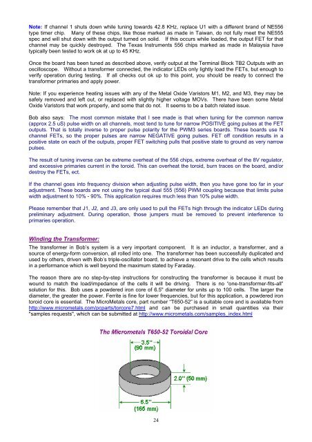
Note: If channel 1 shuts down while tuning towards 42.8 KHz, replace U1 with a different brand of NE556type timer chip. Many of these chips, like those marked as made in Taiwan, do not fully meet the NE555spec and will shut down with the output turned on solid. If this occurs while loaded, the output FET for thatchannel may be quickly destroyed. The Texas Instruments 556 chips marked as made in Malaysia havetypically been tested to work ok at up to 45 KHz.Once the board has been tuned as described above, verify output at the Terminal Block TB2 Outputs with anoscilloscope. Without a transformer connected, the indicator LEDs only lightly load the FETs, but enough toverify operation during testing. If all checks out ok up to this point, you should be ready to connect thetransformer primaries and apply power.Note: If you experience heating issues with any of the Metal Oxide Varistors M1, M2, and M3, they may besafely removed and left out, or replaced with slightly higher voltage MOVs. There have been some MetalOxide Varistors that work properly, and some that do not. It seems to be a batch related issue.Bob also says: The most common mistake that I see made is that when tuning for the common narrow(approx 2.5 uS) pulse width on all channels, most tend to tune for narrow POSITIVE going pulses at the FEToutputs. That is totally inverse to proper pulse polarity for the PWM3 series boards. These boards use Nchannel FETs, so the proper pulses are narrow NEGATIVE going pulses. FET off condition results in apositive state on each of the outputs, proper FET switching pulls that positive state to ground as very narrowpulses.The result of tuning inverse can be extreme overheat of the 556 chips, extreme overheat of the 8V regulator,and excessive primaries current in the toroid. This can overheat the toroid, burn traces on the board, and/ordestroy the FETs, ect.If the channel goes into frequency division when adjusting pulse width, then you have gone too far in youradjustment. These boards are not using the typical dual 555 (556) PWM coupling because that limits pulsewidth adjustment to 10% - 90%. This application requires much less than 10% pulse width.Please remember that J1, J2, and J3, are only used to pull the FETs high through the indicator LEDs duringpreliminary adjustment. During operation, those jumpers must be removed to prevent interference toprimaries operation.Winding the Transformer:The transformer in Bob’s system is a very important component. It is an inductor, a transformer, and asource of energy-form conversion, all rolled into one. The transformer has been successfully duplicated andused by others, driven with Bob’s triple-oscillator board, to achieve a resonant drive to the cells which resultsin a performance which is well beyond the maximum stated by Faraday.The reason there are no step-by-step instructions for constructing the transformer is because it must bewound to match the load/impedance of the cells it will be driving. There is no “one-transformer-fits-all”solution for this. Bob uses a powdered iron core of 6.5" diameter for units up to 100 cells. The larger thediameter, the greater the power. Ferrite is fine for lower frequencies, but for this application, a powdered irontoroid core is essential. The MicroMetals core, part number “T650-52” is a suitable core and is available fromhttp://www.micrometals.com/pcparts/torcore7.html and can be purchased in small quantities via their"samples requests", which can be submitted at http://www.micrometals.com/samples_index.html24


