

Electrolyser designs - Free Energy Info
Electrolyser designs - Free Energy Info
Electrolyser designs - Free Energy Info
- No tags were found...

You also want an ePaper? Increase the reach of your titles
YUMPU automatically turns print PDFs into web optimized ePapers that Google loves.
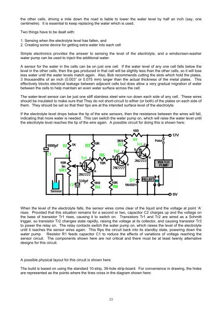
the other cells, driving a mile down the road is liable to lower the water level by half an inch (say, onecentimetre). It is essential to keep replacing the water which is used.Two things have to be dealt with:1. Sensing when the electrolyte level has fallen, and2. Creating some device for getting extra water into each cellSimple electronics provides the answer to sensing the level of the electrolyte, and a windscreen-washerwater pump can be used to inject the additional water.A sensor for the water in the cells can be on just one cell. If the water level of any one cell falls below thelevel in the other cells, then the gas produced in that cell will be slightly less than the other cells, so it will loseless water until the water levels match again. Also, Bob recommends cutting the slots which hold the plates,3 thousandths of an inch (0.003” or 0.075 mm) larger than the actual thickness of the metal plates. Thiseffectively blocks electrical leakage between adjacent cells but does allow a very gradual migration of waterbetween the cells to help maintain an even water surface across the cell.The water-level sensor can be just one stiff stainless steel wire run down each side of any cell. These wiresshould be insulated to make sure that They do not short-circuit to either (or both) of the plates on each side ofthem. They should be set so that their tips are at the intended surface level of the electrolyte.If the electrolyte level drops below the tip of the wire sensors, then the resistance between the wires will fall,indicating that more water is needed. This can switch the water pump on, which will raise the water level untilthe electrolyte level reaches the tip of the wire again. A possible circuit for doing this is shown here:When the level of the electrolyte falls, the sensor wires come clear of the liquid and the voltage at point ‘A’rises. Provided that this situation remains for a second or two, capacitor C2 charges up and the voltage onthe base of transistor Tr1 rises, causing it to switch on. Transistors Tr1 and Tr2 are wired as a Schmitttrigger, so transistor Tr2 changes state rapidly, raising the voltage at its collector, and causing transistor Tr3to power the relay on. The relay contacts switch the water pump on, which raises the level of the electrolyteuntil it reaches the sensor wires again. This flips the circuit back into its standby state, powering down thewater pump. Resistor R1 feeds capacitor C1 to reduce the effects of variations of voltage reaching thesensor circuit. The components shown here are not critical and there must be at least twenty alternative<strong>designs</strong> for this circuit.A possible physical layout for this circuit is shown here:The build is based on using the standard 10-strip, 39-hole strip-board. For convenience in drawing, the holesare represented as the points where the lines cross in the diagram shown here:33


