Circulating Pumps I&O - Armstrong Pumps
Circulating Pumps I&O - Armstrong Pumps
Circulating Pumps I&O - Armstrong Pumps

You also want an ePaper? Increase the reach of your titles
YUMPU automatically turns print PDFs into web optimized ePapers that Google loves.
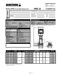
Installation & Operating InstructionsCIRCULATING PUMPSModels S25 to S69, H32 and H41Leaflet No. 1-3/OM/1Date: Jan 2005Supercedes: K5.500Date: Mar 1991INSTALLATIONFor convenience, these circulators are generallyinstalled in a vertical position, but may be changedeasily on the job for horizontal pipelines or for oppositeflow directions. To make the change, remove the bodycapscrews, taking care body gasket is kept in position,and rotate body to desired direction at 90° or 180° fromthe original position. With arrow on body pointing indirection of flow, insert body capscrews, and tightenevenly: turn pump shaft by hand, taking hold of thecoupler to make sure shaft turns freely and that impellerdoes not rub in body. Always install with motor shaft in ahorizontal position with pump and motor oil cups on top.Models S25-S46, H32 & H41 are shipped for downdischarge. Models S55 to S69, suitable for largerinstallations with greater heads, are shipped for updischarge,as pumps of this size are usually installed topump upward on systems, so the point of zero pressurechange – can be easily made to the system on thesuction side of the circulator.The pump should be installed in a position to permitproper lubrication and servicing. Motor and bearingbracket are to be kept free of insulation. A height ofapproximately 4 feet above floor is recommended.When placing pump between flanges. Tighten flangebolts evenly and do not tighten excessively.Gate valves should be installed on discharge andsuction side of pump to facilitate service. On largerpump sizes, a check valve can be located on dischargeside of pump between pump body and gate valve toprevent damage due to water hammer.SYSTEM CLEANLINESSSTARTING THE PUMPThe pump must be fully primed on start-up. Fill systempiping and pump body with liquid and vent completesystem, turning pump by hand to discharge air frombody. Make sure fittings and drain valves are air-tight,then add any additional fill required.Check motor electrics against available supply, thenstart pump, making sure rotation is correct: when viewedfrom motor end, rotation is counter-clockwise on modelsS25 – S46 and on models H32 – H41.On models S55 – S69, rotation is clockwise. If pressuredoes not develop stop pump, re-check, vent and fill.Never attempt to fill system when pump is running.CAUTIONDo not fit support under motor.Before operating pump, carefully check:1) Is the pump primed ?2) Is rotation correct ?3) Is pump properly lubricated ?4) Does the power supply agree with data onmotor nameplate ?5) Is overload protection provided ?6) Is the system clean ?Before starting the pump, the system must bethoroughly cleaned, flushed and drained, thenreplenished with clean liquid. Welding slag and otherforeign materials “stop leak” and cleaning compounds,excessive or improper water treatment – are alldetrimental to the pump internals. Guarantee will be voidif any of these conditions are allowed to exist.FOR DOMESTIC WATER SYSTEMS USE BRONZE BODY PUMPS
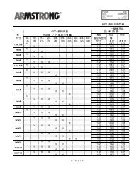
LUBRICATIONStop motor while adding oil.PUMP LUBRICATIONFor maximum water temperature upto 275°F use a non -detergent Shell Oil Tellus 68 or equivalent.Immediately after pump is installed and before running,slowly add oil to oil cup located on top of pump bearingassembly, as follows:Pump Model No.Cast Iron or BronzeS25 to S57H32 and H41S69Quantity ofTellus 68 OilAdd contents of oil bottleSupplied (5/8 oz)Add contents of bottleSupplied (3.75 oz) untiloil is visible between topand centre of viewwindow.At the start of each following heating season, lubricatewith Tellus 68 oil or equivalent:-S25 – S57, H32 and H41 – add approx ½ oz.Lubricate every 6 months for temperatures above 225°For constant operation. On model S69, be sure oil isvisible between top and centre of window on side ofbearing assembly and maintain this level at all times.CAUTION: Do not over oil or spill on resilient motorrings fitted to models S25 to S57, H32 and H41.For maximum water temperature over 225°F to amaximum design temperature of 275°F special Vitonmechanical seals are available.MOTOR LUBRICATIONOil cups are not provided on the 1/12 HP motorssupplied with the S25 circulating pumps. These motorsare fitted with Permawick bearings and the oil capacityis adequate to permit reliable operation for long periods.On motors with oil cups, add approximately 15 drops ofoil to each cup at the start of each following heatingseason. (Lubricate every 6 months for high temperatureor constant operation). Do not force oil into cups, andstop if cup fills before addition of specified amount. Ifmotor is fitted with grease fittings, follow motormanufacturers recommended procedure. Motors withoutoil cups or grease fittings are custom-greased forseveral years operation and require little or no attention.SEAL REPLACEMENTAmongst the common causes of early seal failure arecareless handling of the seal faces or flexible membersduring fitting. The faces of the mechanical seals are veryhighly lapped and care must be taken to ensure that thelapped sealing surfaces are not scratched or chopped.Remover impeller, damaged seal assembly, alsoceramic insert and retainer cup, where applicable. Cleanthe seal faces of bearing bracket. On units usingceramic face, clean the recess and install new retainercup and ceramic. Check condition of shaft sleeve. Ifscored, replace the shaft assembly, otherwise cleanshaft extension and polish sleeve with fine crocus clothif required.Press against coupler end of shaft to take up end play,while pressing seal firmly against stationary face. Aslight amount of clean washing detergent (similar to fairyliquid) may be put on shaft sleeve to assist installation.Do not use spring washer on S25, S34, S35 and H32current style circulators, where spigot to locate spring isprovided on impeller hub.Continue pressing against coupler end of shaft, remountimpeller and re-assemble the seal bearing assembly intobody. Install a new body gasket and clean gasketsurface of both volute and bracket coverplate ifnecessary.AH 2063